2010 JAGUAR XFR 417-01
[x] Cancel search: 417-01Page 22 of 3039

Operation and
Component DescriptionCellular PhoneComponent
Location
Overview
System Operation
and Component DescriptionNavigation SystemComponent Location
Overview
System Operation and Component DescriptionVideo SystemComponent
Location
Overview
System Operation
and Component DescriptionDiagnosis and TestingInformation and Entertainment SystemRemoval and InstallationAudio Unit
Audio Unit Antenna Amplifier
Audio and Climate Control Assembly
Front Door Speaker
Information and Entertainment Display
Information and Entertainment Module
Instrument Panel Speaker
Rear Door Speaker
Steering Wheel Audio Controls
Subwoofer Amplifier
Subwoofer Speaker
Satellite Radio Tuner415-01B: Information and Entertainment System - DTC: Audio Input Control Module
Diagnosis and TestingAudio Input Control Module417: Lighting
417-01: Exterior LightingSpecificationDescription and OperationComponent Location
Overview
System Operation and Component DescriptionDiagnosis and TestingHeadlampsGeneral ProceduresHeadlamp Adjustment (86.40.18)
Page 183 of 3039

Published: 12-May-2014
General Information - Diagnostic Trouble Code (DTC) Index DTC: Headlamp
Control Module (HCM)
Description and Operation
Headlamp Leveling Control Module (HLCM)
CAUTION: Diagnosis by substitution from a donor vehicle is NOT acceptable. Substitution of control modules does not
guarantee confirmation of a fault, and may also cause additional faults in the vehicle being tested and/or the donor vehicle.
NOTES:
If a control module or a component is suspect and the vehicle remains under manufacturer warranty, refer to the Warranty
Policy and Procedures manual, or determine if any prior approval programme is in operation, prior to the installation of a new
module/component.
Generic scan tools may not read the codes listed, or may read only 5-digit codes. Match the 5 digits from the scan tool to
the first 5 digits of the 7-digit code listed to identify the fault (the last 2 digits give extra information read by the
manufacturer-approved diagnostic system).
When performing voltage or resistance tests, always use a digital multimeter accurate to three decimal places, and with
an up-to-date calibration certificate. When testing resistance always take the resistance of the digital multimeter leads into
account.
Check and rectify basic faults before beginning diagnostic routines involving pinpoint tests.
Inspect connectors for signs of water ingress, and pins for damage and/or corrosion.
If DTCs are recorded and, after performing the pinpoint tests, a fault is not present, an intermittent concern may be the
cause. Always check for loose connections and corroded terminals.
Check DDW for open campaigns. Refer to the corresponding bulletins and SSMs which may be valid for the specific
customer complaint and carry out the recommendations as required.
The table below lists all Diagnostic Trouble Codes (DTCs) that could be logged in the Headlamp Leveling Control Module
(HLCM). For additional diagnosis and testing information, refer to the relevant Diagnosis and Testing section in the workshop
manual.
For additional information, refer to: Headlamps (417-01 Exterior Lighting, Diagnosis and Testing).
DTC Description Possible Causes Action B1041-04
Leveling Control -
System internal
failures
Module internal
failure
Suspect Headlamp Leveling Module internal fault. Replace
as required, refer to the new module/component
installation note at the top of the DTC Index B1041-54
Leveling Control -
Missing calibration
NOTE: This DTC will
normally be logged when a
new module has been
installed.
Leveling sensor
calibration routine
not carried out
NOTE: Sensor calibration routine must be carried out with the
vehicle unladen.
Calibrate the Headlamp Leveling Sensors using the
manufacturer approved diagnostic system, carry the out
routine 'Headlamp Control Module System Calibration' from
the 'Module programming and configuration - Setup and
Configuration - Lighting' B10AE-11
Headlamp Leveling
Motor - Circuit short
to ground
Headlamp Leveling
Motor Control Circuit -
short to ground
Refer to the electrical circuit diagrams and check Headlamp
Leveling Motor Control Circuit for short to ground B10AE-12
Headlamp Leveling
Motor - Circuit short
to battery
Headlamp Leveling
Motor Control Circuit -
short to power
Refer to the electrical circuit diagrams and check Headlamp
Leveling Motor Control Circuit for short to power
Page 1656 of 3039

Published: 03-Jan-2013
Speed Control - V8 5.0L Petrol/V8 S/C 5.0L Petrol - Speed Control Deactivator
Switch
Removal and Installation
Removal
1. Refer to: Stoplamp Switch (417-01, Removal and Installation).
Installation
1. Refer to: Stoplamp Switch (417-01, Removal and Installation).
Page 2037 of 3039
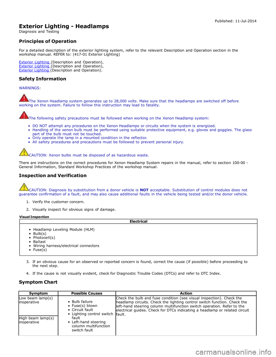
Exterior Lighting - Headlamps
Diagnosis and Testing
Principles of Operation Published: 11-Jul-2014
For a detailed description of the exterior lighting system, refer to the relevant Description and Operation section in the
workshop manual. REFER to: (417-01 Exterior Lighting)
Exterior Lighting (Description and Operation), Exterior Lighting (Description and Operation), Exterior Lighting (Description and Operation).
Safety Information
WARNINGS:
The Xenon Headlamp system generates up to 28,000 volts. Make sure that the headlamps are switched off before
working on the system. Failure to follow this instruction may lead to fatality.
The following safety precautions must be followed when working on the Xenon Headlamp system:
DO NOT attempt any procedures on the Xenon Headlamps or circuits when the system is energized.
Handling of the xenon bulb must be performed using suitable protective equipment, e.g. gloves and goggles. The glass
part of the bulb must not be touched.
Only operate the lamp in a mounted condition in the reflector.
All safety procedures and precautions must be followed to prevent personal injury.
CAUTION: Xenon bulbs must be disposed of as hazardous waste.
There are instructions on the correct procedures for Xenon Headlamp System repairs in the manual, refer to section 100-00 -
General Information, Standard Workshop Practices of the workshop manual.
Inspection and Verification
CAUTION: Diagnosis by substitution from a donor vehicle is NOT acceptable. Substitution of control modules does not
guarantee confirmation of a fault, and may also cause additional faults in the vehicle being tested and/or the donor vehicle.
1. Verify the customer concern.
2. Visually inspect for obvious signs of damage.
3. If an obvious cause for an observed or reported concern is found, correct the cause (if possible) before proceeding to
the next step.
4. If the cause is not visually evident, check for Diagnostic Trouble Codes (DTCs) and refer to DTC Index.
Symptom Chart
Symptom Possible Causes Action Low beam lamp(s)
inoperative
Bulb failure
Fuse(s) blown
Circuit fault
Lighting control switch
fault
Left-hand steering
column multifunction
switch fault Check the bulb and fuse condition (see visual inspection). Check the
headlamp circuits. Check the lighting control switch function. Check the
left-hand steering column multifunction switch operation. Refer to the
electrical guides. Check for DTCs indicating a headlamp or related circuit
fault. High beam lamp(s)
inoperative Electrical
Headlamp Leveling Module (HLM)
Bulb(s)
Photocell(s)
Ballast
Wiring harness/electrical connectors
Fuse(s) Visual Inspection
Page 2219 of 3039
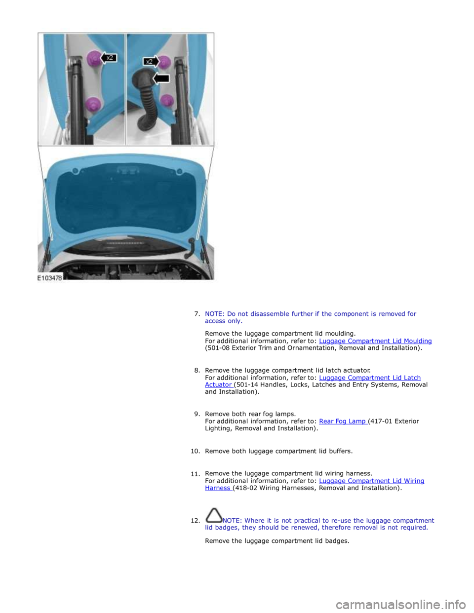
7. NOTE: Do not disassemble further if the component is removed for
access only.
Remove the luggage compartment lid moulding.
For additional information, refer to: Luggage Compartment Lid Moulding (501-08 Exterior Trim and Ornamentation, Removal and Installation).
8. Remove the luggage compartment lid latch actuator.
For additional information, refer to: Luggage Compartment Lid Latch Actuator (501-14 Handles, Locks, Latches and Entry Systems, Removal and Installation).
9. Remove both rear fog lamps.
For additional information, refer to: Rear Fog Lamp (417-01 Exterior Lighting, Removal and Installation).
10. Remove both luggage compartment lid buffers.
11. Remove the luggage compartment lid wiring harness.
For additional information, refer to: Luggage Compartment Lid Wiring Harness (418-02 Wiring Harnesses, Removal and Installation).
12. NOTE: Where it is not practical to re-use the luggage compartment
lid badges, they should be renewed, therefore removal is not required.
Remove the luggage compartment lid badges.
Page 2542 of 3039
On vehicles with headlamp powerwash, each headlamp assembly is fitted with a headlamp powerwasher. The powerwasher is
located on the underside of the headlamp assembly. The powerwasher is located in a clip at the front of the headlamp and
secured with 2 self tapping screws to the headlamp body.
The powerwasher is a telescopic unit which extends forwards from the headlamp assembly under washer fluid pressure
supplied by the headlamp powerwash pump. When the pump pressure decreases the powerwasher is automatically retracted
back into the housing. The outer end of the powerwasher is fitted with a trim which blends the powerwasher into the headlamp
when it is not operating. The powerwasher has two washer jets which direct washer fluid under high pressure onto the
headlamp lens when the powerwasher is extended.
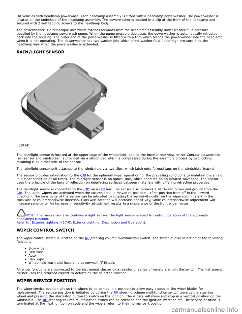
RAIN/LIGHT SENSOR
The rain/light sensor is located at the upper edge of the windshield, behind the interior rear view mirror. Contact between the
rain sensor and windscreen is provided via a silicon pad which is compressed during the assembly process by two locking
retaining clips either side of the sensor.
The rain/light sensor unit attaches to the windshield via two clips, which latch onto formed tags on the windshield bracket.
The sensor provides information to the CJB for the optimum wiper operation for the prevailing conditions to maintain the shield in a clear condition at all times. The rain/light sensor is an optical unit, which operates on an infrared waveband. The sensor
uses the principle of the laws of reflection on interfacing surfaces between materials with differing refraction properties.
The rain/light sensor is connected to the CJB via a LIN bus. The sensor also receives a hardwired power and ground from the CJB. The 'auto' wipers are activated when the column stalk is moved to position 1 (first position from off in the upward direction). The sensitivity of the sensor can be adjusted by rotating the sensitivity collar on the wiper column stalk in the
clockwise or counterclockwise direction. Clockwise rotation will decrease sensitivity, while counterclockwise adjustment will
increase sensitivity. An increase in sensitivity adjustment results in a single wipe of the front wiper motor.
NOTE: The rain sensor also contains a light sensor. The light sensor is used to control operation of the automatic
headlamps function.
Refer to: Exterior Lighting (417-01 Exterior Lighting, Description and Operation).
WIPER CONTROL SWITCH
The wiper control switch is located on the RH steering column multifunction switch. The switch allows selection of the following functions:
Slow wipe
Fast wipe
Auto
Flick wipe
Windshield wash and headlamp powerwash (if fitted).
All wiper functions are connected to the instrument cluster by a resistor or series of resistors within the switch. The instrument
cluster uses the returned current to determine the selected function.
WIPER SERVICE POSITION
The wiper service position allows the wipers to be parked in a position to allow easy access to the wiper blades for
replacement. The service position is initiated by pulling the RH steering column multifunction switch towards the steering wheel and pressing the start/stop button to switch on the ignition. The wipers will move and stop in a vertical position on the
windshield. The RH steering column multifunction switch can be released and the ignition switched off. The service position is terminated at the next ignition on cycle and the wipers return to their normal park position.
Page 2586 of 3039
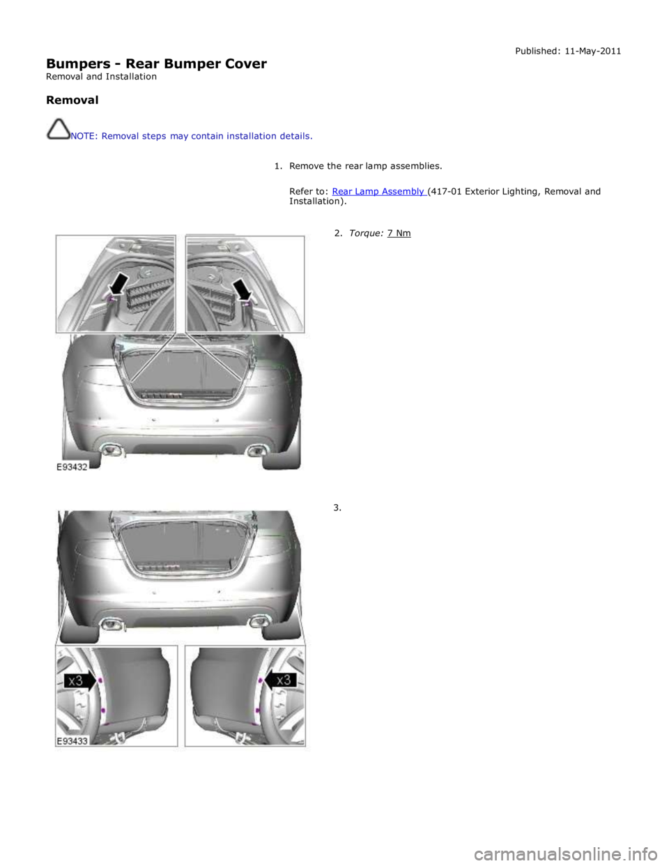
Bumpers - Rear Bumper Cover
Removal and Installation
Removal
NOTE: Removal steps may contain installation details. Published: 11-May-2011
1. Remove the rear lamp assemblies.
Refer to: Rear Lamp Assembly (417-01 Exterior Lighting, Removal and Installation).
2. Torque: 7 Nm 3.
Page 2778 of 3039
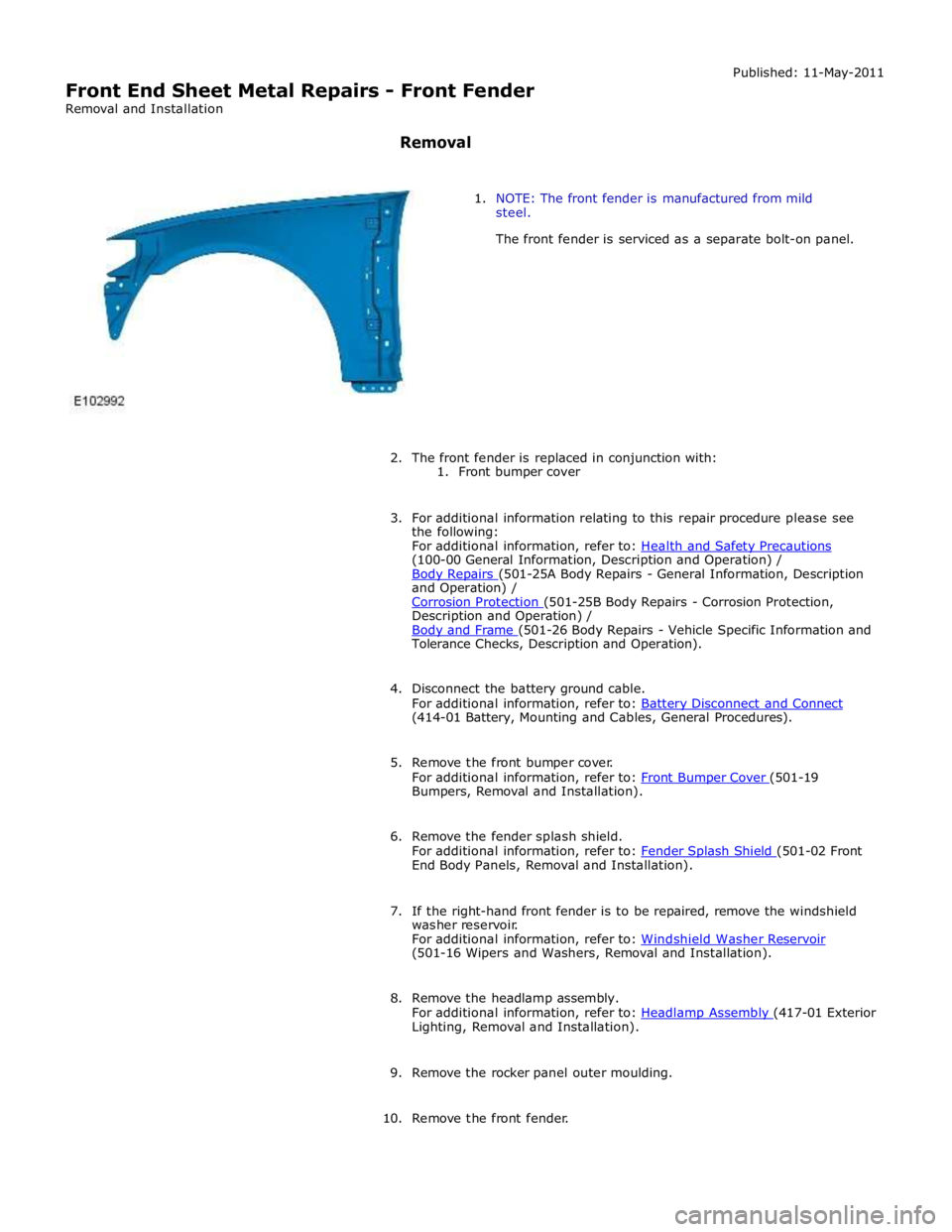
(100-00 General Information, Description and Operation) /
Body Repairs (501-25A Body Repairs - General Information, Description and Operation) /
Corrosion Protection (501-25B Body Repairs - Corrosion Protection, Description and Operation) /
Body and Frame (501-26 Body Repairs - Vehicle Specific Information and Tolerance Checks, Description and Operation).
4. Disconnect the battery ground cable.
For additional information, refer to: Battery Disconnect and Connect (414-01 Battery, Mounting and Cables, General Procedures).
5. Remove the front bumper cover.
For additional information, refer to: Front Bumper Cover (501-19 Bumpers, Removal and Installation).
6. Remove the fender splash shield.
For additional information, refer to: Fender Splash Shield (501-02 Front End Body Panels, Removal and Installation).
7. If the right-hand front fender is to be repaired, remove the windshield
washer reservoir.
For additional information, refer to: Windshield Washer Reservoir (501-16 Wipers and Washers, Removal and Installation).
8. Remove the headlamp assembly.
For additional information, refer to: Headlamp Assembly (417-01 Exterior Lighting, Removal and Installation).
9. Remove the rocker panel outer moulding.
10. Remove the front fender.