2010 JAGUAR XFR Exhaust
[x] Cancel search: ExhaustPage 3 of 3039

Diagnostic Trouble Code (DTC) IndexDTC: Occupant Classification System (OCS)
Diagnostic Trouble Code (DTC) IndexDTC: Parking Aid Module (PAM)
Diagnostic Trouble Code (DTC) IndexDTC: Pedestrian Protection System Control Module (PPSCM)
Diagnostic Trouble Code (DTC) IndexDTC: Rear Differential Control Module (RDCM)
Diagnostic Trouble Code (DTC) IndexDTC: Rear Junction Box (RJB)
Diagnostic Trouble Code (DTC) IndexDTC: Remote Keyless Entry Module (RFA)
Diagnostic Trouble Code (DTC) IndexDTC: Restraints Control Module (RCM)
Diagnostic Trouble Code (DTC) IndexDTC: Satellite Digital Audio Radio System Module (SARM)
Diagnostic Trouble Code (DTC) IndexDTC: Speed Control Module (CCM)
Diagnostic Trouble Code (DTC) IndexDTC: Steering Column Lock Module (VIM)
Diagnostic Trouble Code (DTC) IndexDTC: Television Module (TVM)
Diagnostic Trouble Code (DTC) IndexDTC: Tire Pressure Monitoring System Module (TPM)
Diagnostic Trouble Code (DTC) IndexDTC: Touch Screen Display (FCDIM)
Diagnostic Trouble Code (DTC) IndexVehicles With: 6HP28 6-Speed Automatic Transmission, DTC:
Transmission Control Module (TCM)
Diagnostic Trouble Code (DTC) IndexDTC: Transmission Shift Module (GSM)
Diagnostic Trouble Code (DTC) IndexDTC: Portable Audio Interface Control Module (PAICM)
Diagnostic Trouble Code (DTC) IndexDTC: Hybrid Digital Radio Control Module (HDRCM)
Diagnostic Trouble Code (DTC) IndexDTC: Infotainment Control Module (ICM)
Diagnostic Trouble Code (DTC) IndexDTC: Telephone Module (TEL)100-01: Identification Codes
Description and OperationIdentification Codes100-02: Jacking and Lifting
Description and OperationJacking
Lifting100-04: Noise, Vibration and Harshness
Description and OperationNoise, Vibration and Harshness (NVH)Diagnosis and TestingNoise, Vibration and Harshness (NVH)General ProceduresExhaust System Neutralizing2: Chassis
204: Suspension
204-00: Suspension System - General InformationSpecificationDiagnosis and TestingSuspension SystemGeneral ProceduresCamber and Caster Adjustment
Page 10 of 3039

211-05: Steering Column Switches
Description and OperationComponent Location
Overview
System Operation and Component DescriptionDiagnosis and TestingSteering Column SwitchesRemoval and InstallationHazard Flasher Switch
Steering Column Multifunction Switch LH
Steering Column Multifunction Switch RH
Steering Column Lock Actuator3: Powertrain
303: Engine
303-00: Engine System - General Information
Diagnosis and TestingEngine - 5.0LGeneral ProceduresBearing Inspection
Camshaft Bearing Journal Diameter
Camshaft End Play
Camshaft Lobe Lift
Camshaft Surface Inspection
Connecting Rod Cleaning
Connecting Rod Large End Bore
Crankshaft End Play
Cylinder Bore Out-of-Round
Exhaust Manifold Cleaning and Inspection
Leakage Test Using Smoke Test Equipment
Piston Inspection
Piston Pin Diameter
Piston Pin to Bore Diameter
Piston Ring End Gap
Piston Ring-to-Groove Clearance
Valve Spring Free Length
Valve Stem Diameter
Cylinder Head Distortion
Cylinder Compression Test - V8 S/C 5.0L Petrol303-01D: Engine - V8 S/C 5.0L PetrolSpecificationDescription and OperationComponent Location
Page 11 of 3039

Overview
System Operation and Component DescriptionDiagnosis and TestingEngineGeneral ProceduresEngine Oil Draining and Filling
Engine Oil Vacuum Draining and Filling
Fuel Pump Camshaft Timing Check
Fuel Pump Camshaft Timing Adjustment
Valve Clearance Check
Valve Clearance AdjustmentRemoval and InstallationCamshaft LH
Camshaft RH
Crankshaft Front Seal
Crankshaft Pulley
Crankshaft Rear Seal
Cylinder Head LH
Cylinder Head RH
Engine Mount LH
Engine Mount RH
Exhaust Manifold LH
Exhaust Manifold RH
Flexplate
Oil Cooler
Oil Filter Element
Oil Pan
Oil Pan Extension
Oil Pump
Timing Cover
Timing Drive Components
Valve Cover LH
Valve Cover RH
Cylinder Block Oil Gallery Plug
Fuel Pump Camshaft - Assembly Part Number: INA Timing Drive
Fuel Pump Camshaft - Assembly Part Number: Tsubaki Timing Drive
Lower Timing Cover
ValvesRemovalEngineInstallationEngine
Page 16 of 3039

307-02B: Transmission/Transaxle Cooling - TDV6 3.0L Diesel /V8 5.0L Petrol/V8 S/C 5.0L
PetrolSpecificationDescription and OperationComponent Location
Overview
System Operation and Component DescriptionDiagnosis and TestingTransmission CoolingRemoval and InstallationTransmission Fluid Cooler - V8 5.0L Petrol/V8 S/C 5.0L Petrol
Transmission Fluid Cooler Tubes - V8 5.0L Petrol/V8 S/C 5.0L Petrol307-05B: Automatic Transmission/Transaxle External Controls - TDV6 3.0L Diesel /V8 5.0L
Petrol/V8 S/C 5.0L PetrolSpecificationDescription and OperationComponent Location
Overview
System Operation and Component DescriptionDiagnosis and TestingExternal ControlsRemoval and InstallationTransmission Control Switch (TCS)
Transmission Control Switch (TCS) Knob
Emergency Park Position Release Lever
Upshift
Paddle Switch
Downshift Paddle Switch309: Exhaust System
309-00C: Exhaust System - V8 5.0L Petrol/V8 S/C 5.0L PetrolSpecificationDescription and OperationComponent Location
Overview
System Operation and Component DescriptionDiagnosis and TestingExhaust SystemRemoval and InstallationCatalytic Converter LH
Catalytic Converter RH
Exhaust Sound Enhancement Valve
Exhaust System
Front Muffler
Rear Muffler
Page 51 of 3039

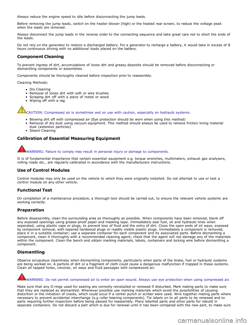
Always reduce the engine speed to idle before disconnecting the jump leads.
Before removing the jump leads, switch on the heater blower (high) or the heated rear screen, to reduce the voltage peak
when the leads are removed.
Always disconnect the jump leads in the reverse order to the connecting sequence and take great care not to short the ends of
the leads.
Do not rely on the generator to restore a discharged battery. For a generator to recharge a battery, it would take in excess of 8
hours continuous driving with no additional loads placed on the battery.
Component Cleaning
To prevent ingress of dirt, accumulations of loose dirt and greasy deposits should be removed before disconnecting or
dismantling components or assemblies.
Components should be thoroughly cleaned before inspection prior to reassembly.
Cleaning Methods:
Dry Cleaning
Removal of loose dirt with soft or wire brushes
Scraping dirt off with a piece of metal or wood
Wiping off with a rag
CAUTION: Compressed air is sometimes wet so use with caution, especially on hydraulic systems.
Blowing dirt off with compressed air (Eye protection should be worn when using this method)
Removal of dry dust using vacuum equipment. This method should always be used to remove friction lining material
dust (asbestos particles)
Steam Cleaning
Calibration of Essential Measuring Equipment
WARNING: Failure to comply may result in personal injury or damage to components.
It is of fundamental importance that certain essential equipment e.g. torque wrenches, multimeters, exhaust gas analysers,
rolling roads etc., are regularly calibrated in accordance with the manufacturers instructions.
Use of Control Modules
Control modules may only be used on the vehicle to which they were originally installed. Do not attempt to use or test a
control module on any other vehicle.
Functional Test
On completion of a maintenance procedure, a thorough test should be carried out, to ensure the relevant vehicle systems are
working correctly.
Preparation
Before disassembly, clean the surrounding area as thoroughly as possible. When components have been removed, blank off
any exposed openings using grease-proof paper and masking tape. Immediately seal fuel, oil and hydraulic lines when
separated, using plastic caps or plugs, to prevent loss of fluid and the entry of dirt. Close the open ends of oil ways, exposed
by component removal, with tapered hardwood plugs or readily visible plastic plugs. Immediately a component is removed,
place it in a suitable container; use a separate container for each component and its associated parts. Before dismantling a
component, clean it thoroughly with a recommended cleaning agent; check that the agent will not damage any of the materials
within the component. Clean the bench and obtain marking materials, labels, containers and locking wire before dismantling a
component.
Dismantling
Observe scrupulous cleanliness when dismantling components, particularly when parts of the brake, fuel or hydraulic systems
are being worked on. A particle of dirt or a fragment of cloth could cause a dangerous malfunction if trapped in these systems.
Clean all tapped holes, crevices, oil ways and fluid passages with compressed air.
WARNING: Do not permit compressed air to enter an open wound. Always use eye protection when using compressed air.
Make sure that any O-rings used for sealing are correctly reinstalled or renewed if disturbed. Mark mating parts to make sure
that they are replaced as dismantled. Whenever possible use marking materials which avoid the possibilities of causing
distortion or the initiation of cracks, which could occur if a center punch or scriber were used. Wire together mating parts where
necessary to prevent accidental interchange (e.g roller bearing components). Tie labels on to all parts to be renewed and to
parts requiring further inspection before being passed for reassembly. Place labelled parts and other parts for rebuild in
separate containers. Do not discard a part which is due for renewal until it has been compared with the new part, to make sure
Page 53 of 3039

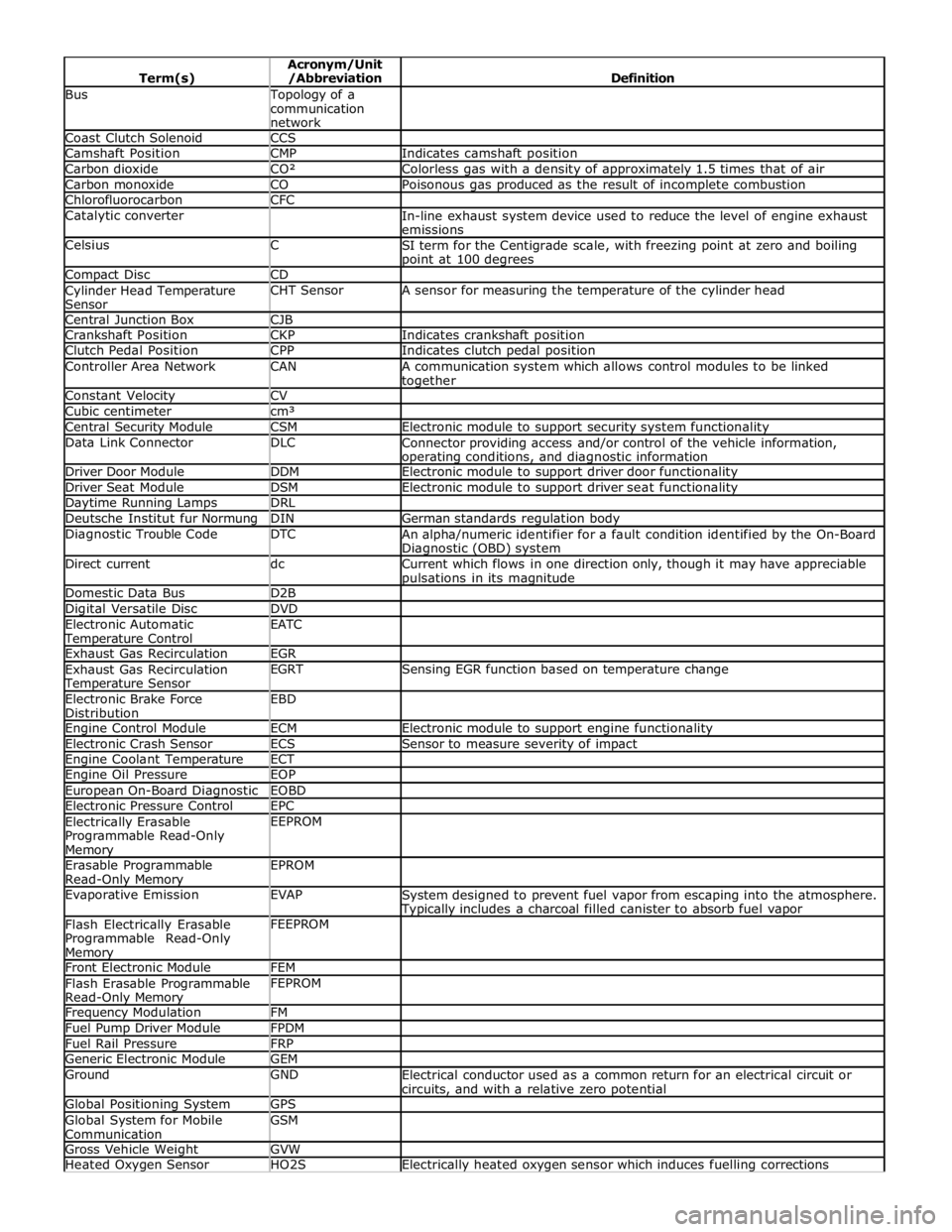
Bus Topology of a
communication
network Coast Clutch Solenoid CCS Camshaft Position CMP Indicates camshaft position Carbon dioxide CO² Colorless gas with a density of approximately 1.5 times that of air Carbon monoxide CO Poisonous gas produced as the result of incomplete combustion Chlorofluorocarbon CFC Catalytic converter
In-line exhaust system device used to reduce the level of engine exhaust
emissions Celsius C
SI term for the Centigrade scale, with freezing point at zero and boiling point at 100 degrees Compact Disc CD Cylinder Head Temperature
Sensor CHT Sensor A sensor for measuring the temperature of the cylinder head Central Junction Box CJB Crankshaft Position CKP Indicates crankshaft position Clutch Pedal Position CPP Indicates clutch pedal position Controller Area Network CAN
A communication system which allows control modules to be linked together Constant Velocity CV Cubic centimeter cm³ Central Security Module CSM Electronic module to support security system functionality Data Link Connector DLC
Connector providing access and/or control of the vehicle information, operating conditions, and diagnostic information Driver Door Module DDM Electronic module to support driver door functionality Driver Seat Module DSM Electronic module to support driver seat functionality Daytime Running Lamps DRL Deutsche Institut fur Normung DIN German standards regulation body Diagnostic Trouble Code DTC
An alpha/numeric identifier for a fault condition identified by the On-Board Diagnostic (OBD) system Direct current dc
Current which flows in one direction only, though it may have appreciable pulsations in its magnitude Domestic Data Bus D2B Digital Versatile Disc DVD Electronic Automatic Temperature Control EATC
Exhaust Gas Recirculation EGR Exhaust Gas Recirculation Temperature Sensor EGRT Sensing EGR function based on temperature change Electronic Brake Force
Distribution EBD
Engine Control Module ECM Electronic module to support engine functionality Electronic Crash Sensor ECS Sensor to measure severity of impact Engine Coolant Temperature ECT Engine Oil Pressure EOP European On-Board Diagnostic EOBD Electronic Pressure Control EPC Electrically Erasable
Programmable Read-Only Memory EEPROM
Erasable Programmable
Read-Only Memory EPROM
Evaporative Emission EVAP
System designed to prevent fuel vapor from escaping into the atmosphere. Typically includes a charcoal filled canister to absorb fuel vapor Flash Electrically Erasable
Programmable Read-Only Memory FEEPROM
Front Electronic Module FEM Flash Erasable Programmable
Read-Only Memory FEPROM
Frequency Modulation FM Fuel Pump Driver Module FPDM Fuel Rail Pressure FRP Generic Electronic Module GEM Ground GND
Electrical conductor used as a common return for an electrical circuit or
circuits, and with a relative zero potential Global Positioning System GPS Global System for Mobile
Communication GSM
Gross Vehicle Weight GVW Heated Oxygen Sensor HO2S Electrically heated oxygen sensor which induces fuelling corrections
Page 54 of 3039

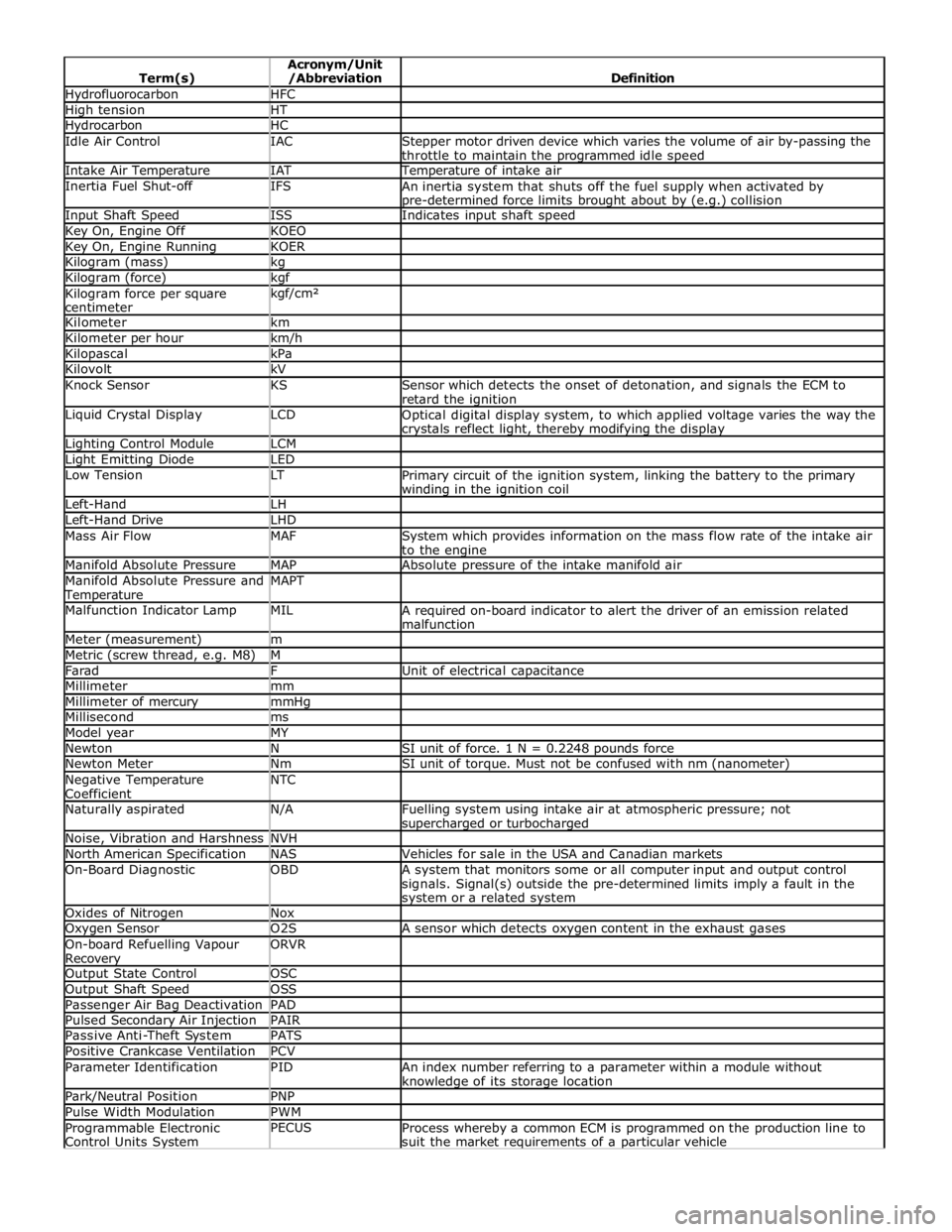
Hydrofluorocarbon HFC High tension HT Hydrocarbon HC Idle Air Control IAC
Stepper motor driven device which varies the volume of air by-passing the
throttle to maintain the programmed idle speed Intake Air Temperature IAT Temperature of intake air Inertia Fuel Shut-off IFS
An inertia system that shuts off the fuel supply when activated by pre-determined force limits brought about by (e.g.) collision Input Shaft Speed ISS Indicates input shaft speed Key On, Engine Off KOEO Key On, Engine Running KOER Kilogram (mass) kg Kilogram (force) kgf Kilogram force per square
centimeter kgf/cm²
Kilometer km Kilometer per hour km/h Kilopascal kPa Kilovolt kV Knock Sensor KS
Sensor which detects the onset of detonation, and signals the ECM to
retard the ignition Liquid Crystal Display LCD
Optical digital display system, to which applied voltage varies the way the crystals reflect light, thereby modifying the display Lighting Control Module LCM Light Emitting Diode LED Low Tension LT
Primary circuit of the ignition system, linking the battery to the primary winding in the ignition coil Left-Hand LH Left-Hand Drive LHD Mass Air Flow MAF
System which provides information on the mass flow rate of the intake air
to the engine Manifold Absolute Pressure MAP Absolute pressure of the intake manifold air Manifold Absolute Pressure and Temperature MAPT
Malfunction Indicator Lamp MIL
A required on-board indicator to alert the driver of an emission related
malfunction Meter (measurement) m Metric (screw thread, e.g. M8) M Farad F Unit of electrical capacitance Millimeter mm Millimeter of mercury mmHg Millisecond ms Model year MY Newton N SI unit of force. 1 N = 0.2248 pounds force Newton Meter Nm SI unit of torque. Must not be confused with nm (nanometer) Negative Temperature
Coefficient NTC
Naturally aspirated N/A
Fuelling system using intake air at atmospheric pressure; not supercharged or turbocharged Noise, Vibration and Harshness NVH North American Specification NAS Vehicles for sale in the USA and Canadian markets On-Board Diagnostic OBD
A system that monitors some or all computer input and output control
signals. Signal(s) outside the pre-determined limits imply a fault in the system or a related system Oxides of Nitrogen Nox Oxygen Sensor O2S A sensor which detects oxygen content in the exhaust gases On-board Refuelling Vapour Recovery ORVR
Output State Control OSC Output Shaft Speed OSS Passenger Air Bag Deactivation PAD Pulsed Secondary Air Injection PAIR Passive Anti-Theft System PATS Positive Crankcase Ventilation PCV Parameter Identification PID
An index number referring to a parameter within a module without knowledge of its storage location Park/Neutral Position PNP Pulse Width Modulation PWM Programmable Electronic
Control Units System PECUS
Process whereby a common ECM is programmed on the production line to
suit the market requirements of a particular vehicle
Page 55 of 3039

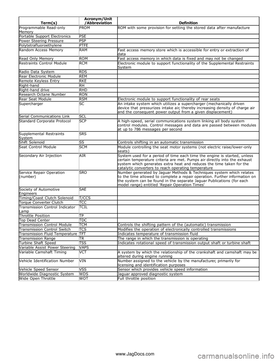
Programmable Read-only Memory PROM ROM with some provision for setting the stored data after manufacture Portable Support Electronics PSE Power Steering Pressure PSP Polytetrafluoroethylene PTFE Random Access Memory RAM
Fast access memory store which is accessible for entry or extraction of
data Read Only Memory ROM Fast access memory in which data is fixed and may not be changed Restraints Control Module RCM
Electronic module to support functionality of the Supplemental Restraints System Radio Data System RDS Rear Electronic Module REM Remote Keyless Entry RKE Right-hand RH Right-hand drive RHD Research Octane Number RON Rear Seat Module RSM Electronic module to support functionality of rear seats Supercharger SC
An intake system which utilizes a supercharger (mechanically driven
device that pressurizes intake air, thereby increasing density of charge air
and the consequent power output from a given displacement) Serial Communications Link SCL Standard Corporate Protocol SCP
A high-speed, serial communications system linking all body system
control modules. Control messages and data are passed between modules
at up to 786 messages per second Supplemental Restraints System SRS
Shift Solenoid SS Controls shifting in an automatic transmission Seat Control Module SCM
Module controlling the seat motor systems (not electric raise/lower-only seats) Secondary Air Injection AIR
System used for a period of time each time the engine is started, unless
certain temperature criteria are met. Pumps air directly into the exhaust
system which generates extra heat and reduces the time taken for the catalytic converters to reach operating temperature Service Repair Operation
(number) SRO
Number generated by Jaguar Methods & Techniques system which relates
to the time allowed to complete a repair operation. Further information on
the system can be found in the separate Jaguar Publications (for each
model range) entitled 'Repair Operation Times' Society of Automotive Engineers SAE
Timing/Coast Clutch Solenoid T/CCS Torque Converter Clutch TCC Transmission Control Indicator
Lamp TCIL
Throttle Position TP Top Dead Center TDC Transmission Control Module TCM Controls the shifting pattern of the (automatic) transmission Transmission Control Switch TCS Modifies the operation of electronically controlled transmissions Transmission Fluid Temperature TFT Indicates temperature of transmission fluid Transmission Range TR The range in which the transmission is operating Turbine Shaft Speed TSS Indicates rotational speed of transmission output shaft or turbine shaft Variable Assist Power Steering VAPS Variable Camshaft Timing VCT
A system by which the relationship of the crankshaft and camshaft may be
altered during engine running Vehicle Identification Number VIN
Number assigned to the vehicle by the manufacturer, primarily for licensing and identification purposes Vehicle Speed Sensor VSS Sensor which provides vehicle speed information Worldwide Diagnostic System WDS Jaguar approved diagnostic system Wide Open Throttle WOT Full throttle position www.JagDocs.com