2010 JAGUAR XFR navigation update
[x] Cancel search: navigation updatePage 21 of 3039

Quiescent Drain
Battery Report Form – In Service Batteries OnlyDiagnosis and TestingCharging System414-01: Battery, Mounting and CablesSpecificationDescription and OperationComponent Location
Overview
System Operation and Component DescriptionDiagnosis and TestingBatteryGeneral ProceduresBattery Disconnect and ConnectRemoval and InstallationBattery414-02C: Generator and Regulator - V8 5.0L Petrol/V8 S/C 5.0L PetrolSpecificationDescription and OperationComponent Location
Overview
System Operation and Component DescriptionRemoval and InstallationGenerator - V8 S/C 5.0L Petrol415: Information and Entertainment Systems
415-00: Information and Entertainment System - General Information
Description and OperationNavigation System Map UpdatesDiagnosis and TestingInformation and Entertainment System
Cellular Phone
Navigation System415-01A: Information and Entertainment SystemSpecification
Description and OperationAudio SystemComponent Location
Overview
System Operation and Component DescriptionSpeakersComponent Location
Overview
Page 1915 of 3039
Published: 24-Mar-2014
Information and Entertainment System - General Information - Navigation
System Map Updates
Description and Operation
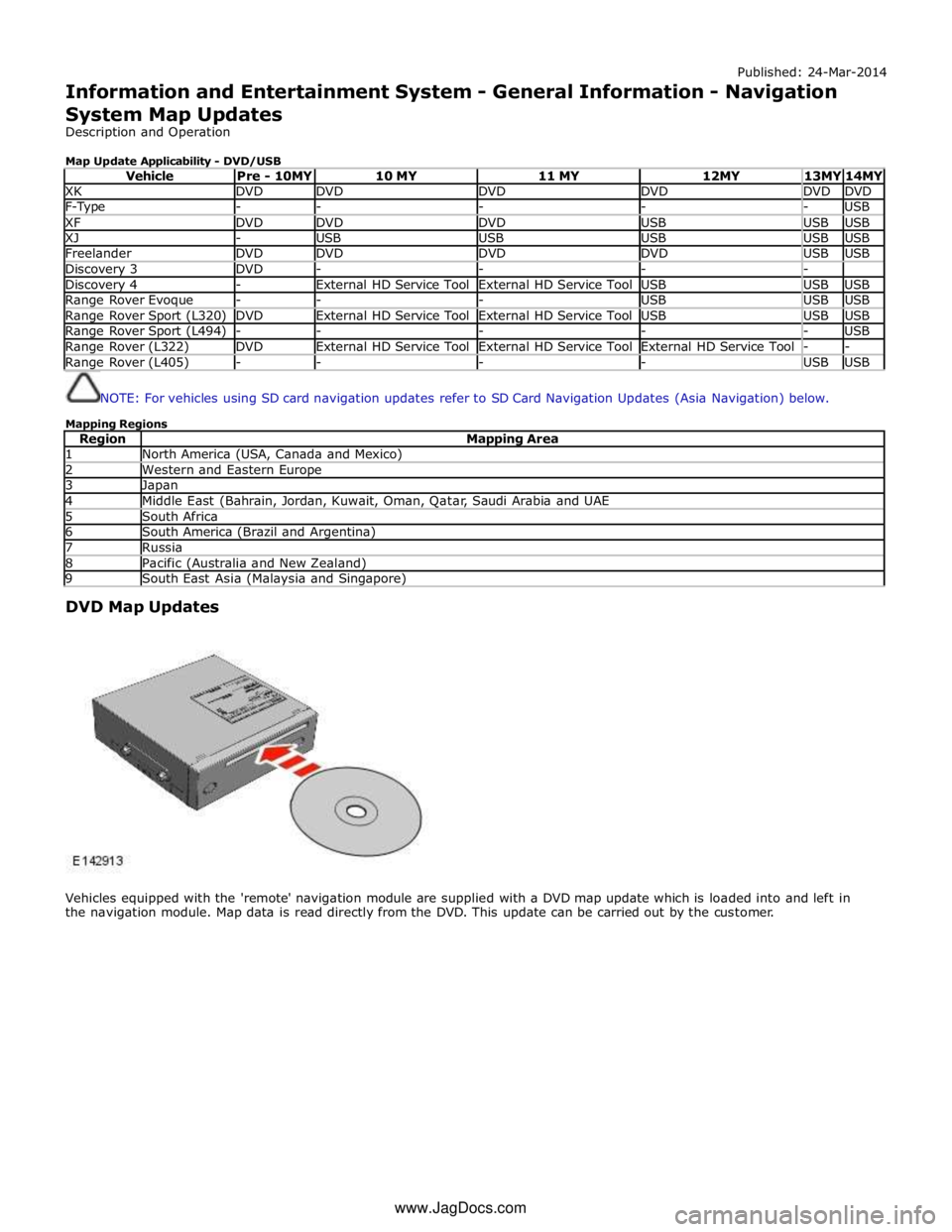
Map Update Applicability - DVD/USB
Vehicle Pre - 10MY 10 MY 11 MY 12MY 13MY 14MY XK DVD DVD DVD DVD DVD DVD F-Type - - - - - USB XF DVD DVD DVD USB USB USB XJ - USB USB USB USB USB Freelander DVD DVD DVD DVD USB USB Discovery 3 DVD - - - - Discovery 4 - External HD Service Tool External HD Service Tool USB USB USB Range Rover Evoque - - - USB USB USB Range Rover Sport (L320) DVD External HD Service Tool External HD Service Tool USB USB USB Range Rover Sport (L494) - - - - - USB Range Rover (L322) DVD External HD Service Tool External HD Service Tool External HD Service Tool - - Range Rover (L405) - - - - USB USB
NOTE: For vehicles using SD card navigation updates refer to SD Card Navigation Updates (Asia Navigation) below.
Mapping Regions
Region Mapping Area 1 North America (USA, Canada and Mexico) 2 Western and Eastern Europe 3 Japan 4 Middle East (Bahrain, Jordan, Kuwait, Oman, Qatar, Saudi Arabia and UAE 5 South Africa 6 South America (Brazil and Argentina) 7 Russia 8 Pacific (Australia and New Zealand) 9 South East Asia (Malaysia and Singapore)
DVD Map Updates
Vehicles equipped with the 'remote' navigation module are supplied with a DVD map update which is loaded into and left in
the navigation module. Map data is read directly from the DVD. This update can be carried out by the customer. www.JagDocs.com
Page 1916 of 3039
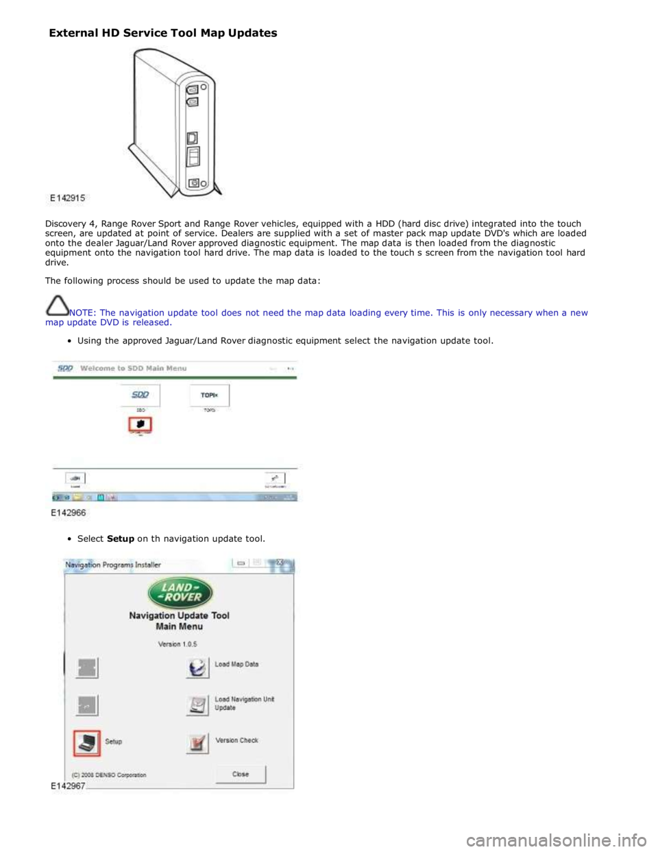
External HD Service Tool Map Updates
Discovery 4, Range Rover Sport and Range Rover vehicles, equipped with a HDD (hard disc drive) integrated into the touch
screen, are updated at point of service. Dealers are supplied with a set of master pack map update DVD's which are loaded
onto the dealer Jaguar/Land Rover approved diagnostic equipment. The map data is then loaded from the diagnostic
equipment onto the navigation tool hard drive. The map data is loaded to the touch s screen from the navigation tool hard
drive.
The following process should be used to update the map data:
NOTE: The navigation update tool does not need the map data loading every time. This is only necessary when a new
map update DVD is released.
Using the approved Jaguar/Land Rover diagnostic equipment select the navigation update tool.
Select Setup on th navigation update tool.
Page 1929 of 3039
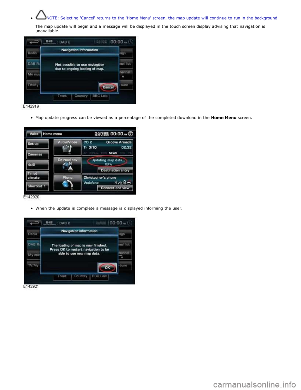
NOTE: Selecting 'Cancel' returns to the 'Home Menu' screen, the map update will continue to run in the background
The map update will begin and a message will be displayed in the touch screen display advising that navigation is
unavailable.
Map update progress can be viewed as a percentage of the completed download in the Home Menu screen.
When the update is complete a message is displayed informing the user.
Page 1930 of 3039
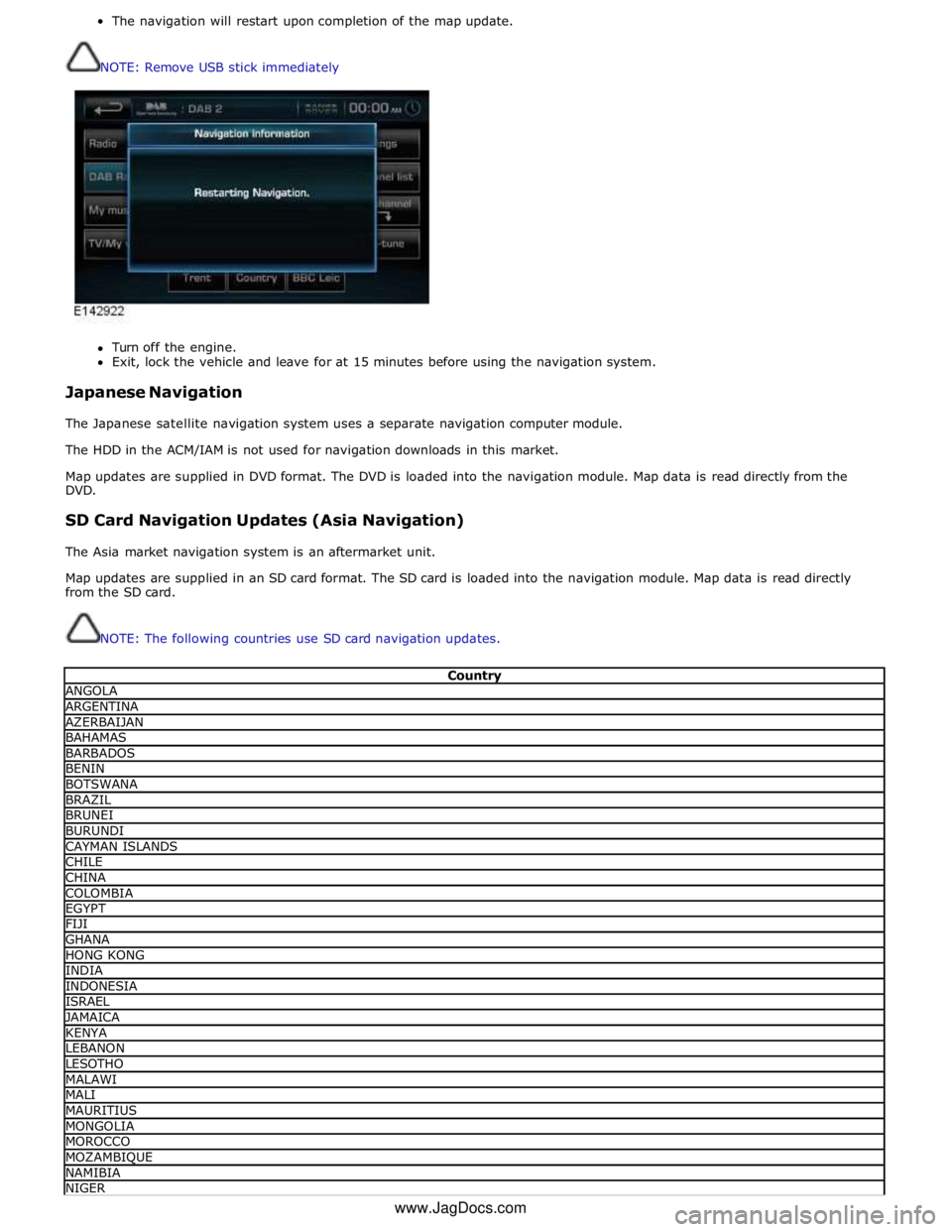
The navigation will restart upon completion of the map update.
NOTE: Remove USB stick immediately
Turn off the engine.
Exit, lock the vehicle and leave for at 15 minutes before using the navigation system.
Japanese Navigation
The Japanese satellite navigation system uses a separate navigation computer module.
The HDD in the ACM/IAM is not used for navigation downloads in this market.
Map updates are supplied in DVD format. The DVD is loaded into the navigation module. Map data is read directly from the
DVD.
SD Card Navigation Updates (Asia Navigation)
The Asia market navigation system is an aftermarket unit.
Map updates are supplied in an SD card format. The SD card is loaded into the navigation module. Map data is read directly
from the SD card.
NOTE: The following countries use SD card navigation updates.
Country ANGOLA ARGENTINA AZERBAIJAN BAHAMAS BARBADOS BENIN BOTSWANA BRAZIL BRUNEI BURUNDI CAYMAN ISLANDS CHILE CHINA COLOMBIA EGYPT FIJI GHANA HONG KONG INDIA INDONESIA ISRAEL JAMAICA KENYA LEBANON LESOTHO MALAWI MALI MAURITIUS MONGOLIA MOROCCO MOZAMBIQUE NAMIBIA NIGER www.JagDocs.com
Page 1949 of 3039
systems.
A typical example of information transfer is vehicle speed information from the ABS (anti-lock brake system) module used to
control the automatic volume control function. The vehicle speed information from the ABS module is sent on the high speed
CAN network and collected by the instrument panel gateway. The signal is passed to the medium speed CAN network and onto the ICM gateway. The ICM calculates the volume adjustment required. The corrected audio volume level signal is sent on the
MOST network to the IAM or Power amplifier (dependant on vehicle equipment level) for output to the speaker system.
AUDIO SYSTEM USER CONTROLS
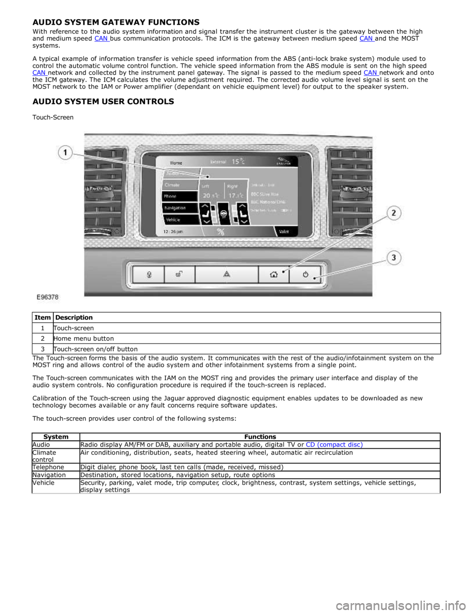
Touch-Screen
Item Description 1 Touch-screen 2 Home menu button 3 Touch-screen on/off button The Touch-screen forms the basis of the audio system. It communicates with the rest of the audio/infotainment system on the
MOST ring and allows control of the audio system and other infotainment systems from a single point.
The Touch-screen communicates with the IAM on the MOST ring and provides the primary user interface and display of the
audio system controls. No configuration procedure is required if the touch-screen is replaced.
Calibration of the Touch-screen using the Jaguar approved diagnostic equipment enables updates to be downloaded as new
technology becomes available or any fault concerns require software updates.
The touch-screen provides user control of the following systems:
System Functions Audio Radio display AM/FM or DAB, auxiliary and portable audio, digital TV or CD (compact disc) Climate
control Air conditioning, distribution, seats, heated steering wheel, automatic air recirculation Telephone Digit dialer, phone book, last ten calls (made, received, missed) Navigation Destination, stored locations, navigation setup, route options Vehicle
Security, parking, valet mode, trip computer, clock, brightness, contrast, system settings, vehicle settings, display settings
Page 1953 of 3039
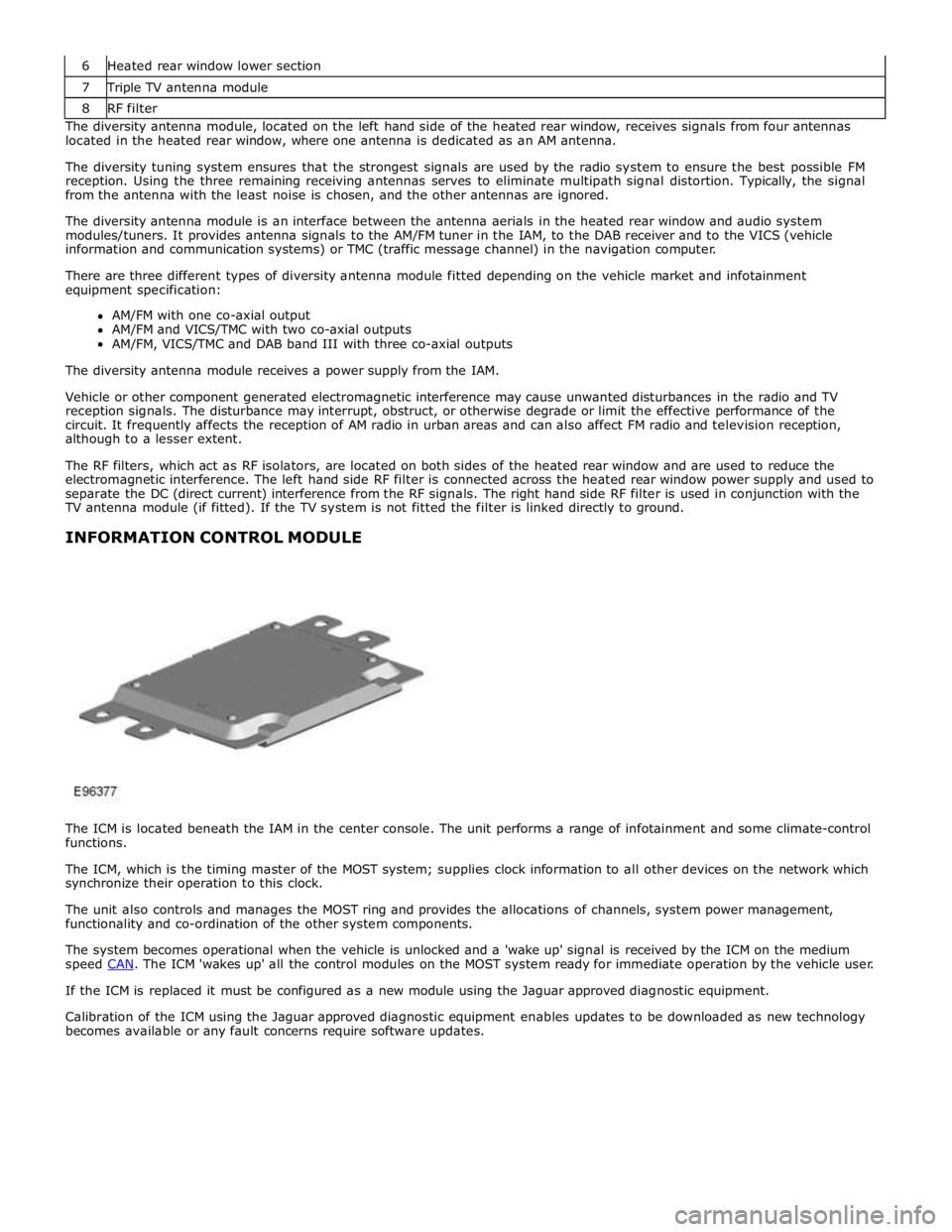
7 Triple TV antenna module 8 RF filter The diversity antenna module, located on the left hand side of the heated rear window, receives signals from four antennas
located in the heated rear window, where one antenna is dedicated as an AM antenna.
The diversity tuning system ensures that the strongest signals are used by the radio system to ensure the best possible FM
reception. Using the three remaining receiving antennas serves to eliminate multipath signal distortion. Typically, the signal
from the antenna with the least noise is chosen, and the other antennas are ignored.
The diversity antenna module is an interface between the antenna aerials in the heated rear window and audio system
modules/tuners. It provides antenna signals to the AM/FM tuner in the IAM, to the DAB receiver and to the VICS (vehicle
information and communication systems) or TMC (traffic message channel) in the navigation computer.
There are three different types of diversity antenna module fitted depending on the vehicle market and infotainment
equipment specification:
AM/FM with one co-axial output
AM/FM and VICS/TMC with two co-axial outputs
AM/FM, VICS/TMC and DAB band III with three co-axial outputs
The diversity antenna module receives a power supply from the IAM.
Vehicle or other component generated electromagnetic interference may cause unwanted disturbances in the radio and TV
reception signals. The disturbance may interrupt, obstruct, or otherwise degrade or limit the effective performance of the
circuit. It frequently affects the reception of AM radio in urban areas and can also affect FM radio and television reception,
although to a lesser extent.
The RF filters, which act as RF isolators, are located on both sides of the heated rear window and are used to reduce the
electromagnetic interference. The left hand side RF filter is connected across the heated rear window power supply and used to
separate the DC (direct current) interference from the RF signals. The right hand side RF filter is used in conjunction with the
TV antenna module (if fitted). If the TV system is not fitted the filter is linked directly to ground.
INFORMATION CONTROL MODULE
The ICM is located beneath the IAM in the center console. The unit performs a range of infotainment and some climate-control
functions.
The ICM, which is the timing master of the MOST system; supplies clock information to all other devices on the network which
synchronize their operation to this clock.
The unit also controls and manages the MOST ring and provides the allocations of channels, system power management,
functionality and co-ordination of the other system components.
The system becomes operational when the vehicle is unlocked and a 'wake up' signal is received by the ICM on the medium
speed CAN. The ICM 'wakes up' all the control modules on the MOST system ready for immediate operation by the vehicle user. If the ICM is replaced it must be configured as a new module using the Jaguar approved diagnostic equipment.
Calibration of the ICM using the Jaguar approved diagnostic equipment enables updates to be downloaded as new technology
becomes available or any fault concerns require software updates.
Page 1958 of 3039
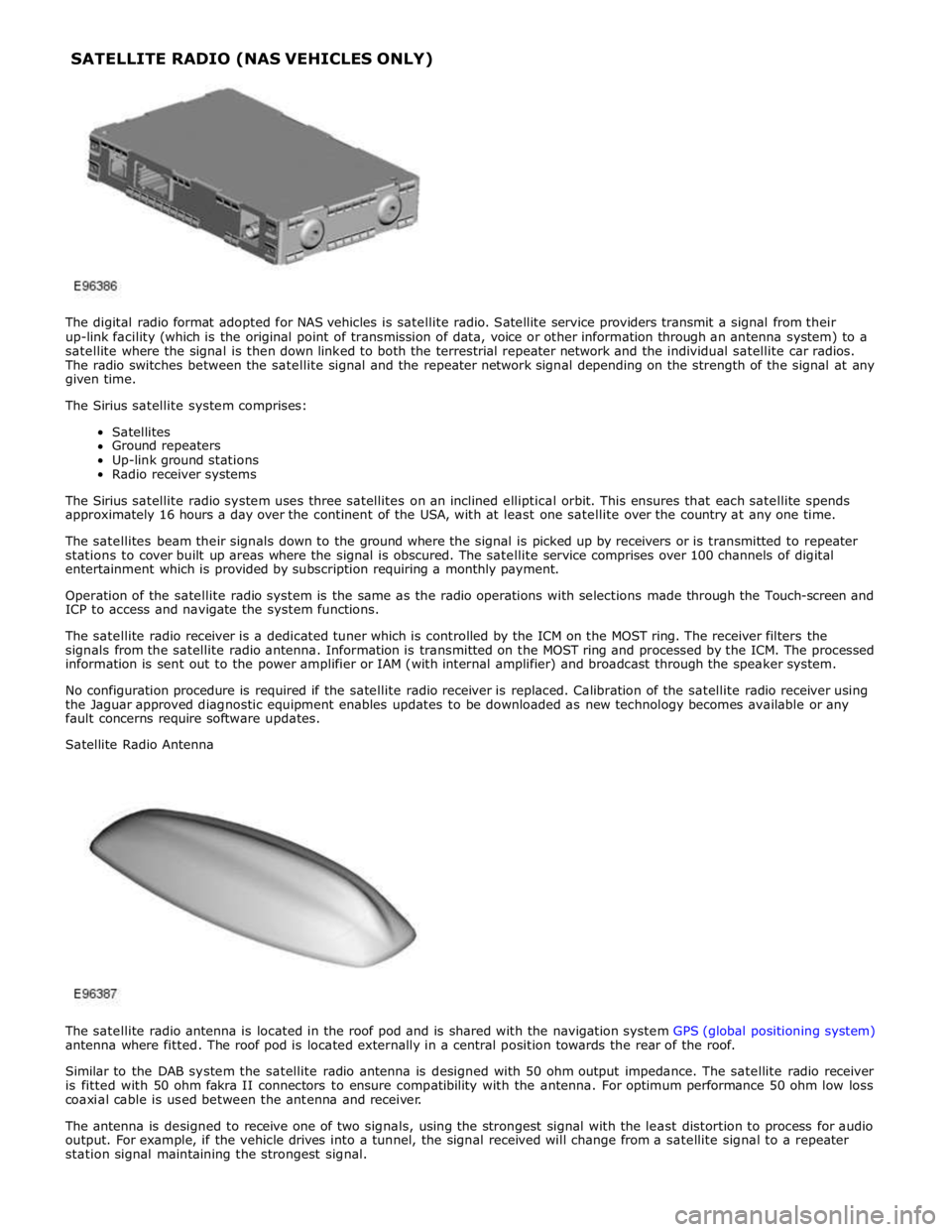
The digital radio format adopted for NAS vehicles is satellite radio. Satellite service providers transmit a signal from their
up-link facility (which is the original point of transmission of data, voice or other information through an antenna system) to a
satellite where the signal is then down linked to both the terrestrial repeater network and the individual satellite car radios.
The radio switches between the satellite signal and the repeater network signal depending on the strength of the signal at any
given time.
The Sirius satellite system comprises:
Satellites
Ground repeaters
Up-link ground stations
Radio receiver systems
The Sirius satellite radio system uses three satellites on an inclined elliptical orbit. This ensures that each satellite spends
approximately 16 hours a day over the continent of the USA, with at least one satellite over the country at any one time.
The satellites beam their signals down to the ground where the signal is picked up by receivers or is transmitted to repeater
stations to cover built up areas where the signal is obscured. The satellite service comprises over 100 channels of digital
entertainment which is provided by subscription requiring a monthly payment.
Operation of the satellite radio system is the same as the radio operations with selections made through the Touch-screen and
ICP to access and navigate the system functions.
The satellite radio receiver is a dedicated tuner which is controlled by the ICM on the MOST ring. The receiver filters the
signals from the satellite radio antenna. Information is transmitted on the MOST ring and processed by the ICM. The processed
information is sent out to the power amplifier or IAM (with internal amplifier) and broadcast through the speaker system.
No configuration procedure is required if the satellite radio receiver is replaced. Calibration of the satellite radio receiver using
the Jaguar approved diagnostic equipment enables updates to be downloaded as new technology becomes available or any
fault concerns require software updates.
Satellite Radio Antenna
The satellite radio antenna is located in the roof pod and is shared with the navigation system GPS (global positioning system)
antenna where fitted. The roof pod is located externally in a central position towards the rear of the roof.
Similar to the DAB system the satellite radio antenna is designed with 50 ohm output impedance. The satellite radio receiver
is fitted with 50 ohm fakra II connectors to ensure compatibility with the antenna. For optimum performance 50 ohm low loss
coaxial cable is used between the antenna and receiver.
The antenna is designed to receive one of two signals, using the strongest signal with the least distortion to process for audio
output. For example, if the vehicle drives into a tunnel, the signal received will change from a satellite signal to a repeater
station signal maintaining the strongest signal. SATELLITE RADIO (NAS VEHICLES ONLY)