2010 JAGUAR XFR bluetooth
[x] Cancel search: bluetoothPage 24 of 3039

System Operation and Component DescriptionDiagnosis and TestingAnti-Theft - ActiveRemoval and InstallationAnti-Theft Alarm Horn (86.52.03)419-01B: Anti-Theft - Passive
Description and OperationComponent Location
Overview
System Operation and Component DescriptionDiagnosis and TestingAnti-Theft - Passive419-05: Telematics
Diagnosis and TestingTelematics419-07: Navigation System
Description and Operation Diagnosis and TestingNavigation SystemRemoval and InstallationNavigation System Antenna (86.62.06)
Navigation System Module (86.62.05)419-08: Cellular Phone
Removal and InstallationBluetooth Module419-10: Multifunction Electronic ModulesSpecificationDescription and OperationComponent Location
Overview
System Operation and Component DescriptionDiagnosis and TestingDriver Door Module (DDM)
Remote Keyless Entry (RKE) Module
Passenger Door Module (PDM)Removal and InstallationDriver Door Module (DDM)
Driver Seat Module (DSM)
Passenger Door Module (PDM)
Rear Door Module (RDM)5: Body and Paint
501: Body and Paint
501-02: Front End Body Panels
Page 279 of 3039

Published: 12-May-2014
General Information - Diagnostic Trouble Code (DTC) Index DTC: Telephone
Module (TEL)
Description and Operation
Telephone Module
CAUTION: Diagnosis by substitution from a donor vehicle is NOT acceptable. Substitution of control modules does not
guarantee confirmation of a fault, and may also cause additional faults in the vehicle being tested and/or the donor vehicle.
NOTES:
If a control module or a component is suspect and the vehicle remains under manufacturer warranty, refer to the Warranty
Policy and Procedures manual, or determine if any prior approval programme is in operation, prior to the installation of a new
module/component.
Generic scan tools may not read the codes listed, or may read only 5-digit codes. Match the 5 digits from the scan tool to
the first 5 digits of the 7-digit code listed to identify the fault (the last 2 digits give extra information read by the
manufacturer-approved diagnostic system).
When performing voltage or resistance tests, always use a digital multimeter accurate to three decimal places, and with
an up-to-date calibration certificate. When testing resistance always take the resistance of the digital multimeter leads into
account.
Check and rectify basic faults before beginning diagnostic routines involving pinpoint tests.
Inspect connectors for signs of water ingress, and pins for damage and/or corrosion.
If DTCs are recorded and, after performing the pinpoint tests, a fault is not present, an intermittent concern may be the
cause. Always check for loose connections and corroded terminals.
Check DDW for open campaigns. Refer to the corresponding bulletins and SSMs which may be valid for the specific
customer complaint and carry out the recommendations as required.
The table below lists all Diagnostic Trouble Codes (DTCs) that could be logged in the Telephone Module. For additional
diagnosis and testing information, refer to the relevant Diagnosis and Testing section in the workshop manual.
For additional information, refer to: Cellular Phone (415-00 Information and Entertainment System - General Information, Diagnosis and Testing).
DTC Description Possible Causes Action B1A56-13 Antenna - Circuit open
Bluetooth antenna circuit
- open circuit
Refer to the electrical circuit diagrams and check blue
tooth antenna circuit for open circuit B1D79-84
Microphone Input -
Signal below
allowable range
Signal amplitude <
minimum
Refer to the electrical circuit diagrams and test
microphone input circuit for short/open circuit. Check
integrated audio module for related DTCs and refer to
relevant DTC Index U1A00-88
Private
Communication
Network - Bus off
Bluetooth phone module
internal communications
failure
Suspect the module. Check and install a new
telephone module as required, refer to the new
module/component installation note at the top of the
DTC Index U2100-00
Initial Configuration
Not Complete - No
sub type information
Initial configuration not
complete
Re-configure the RJB using the manufacturer approved
diagnostic system. If DTC remains, carry out CAN
network integrity tests using the manufacturer
approved diagnostic system U2101-00
Control Module
Configuration
Incompatible - No sub
type information
Configuration
incompatible
Re-configure the RJB using the manufacturer approved
diagnostic system. If DTC remains, suspect the
telephone module. Check and install a new telephone
Page 1934 of 3039
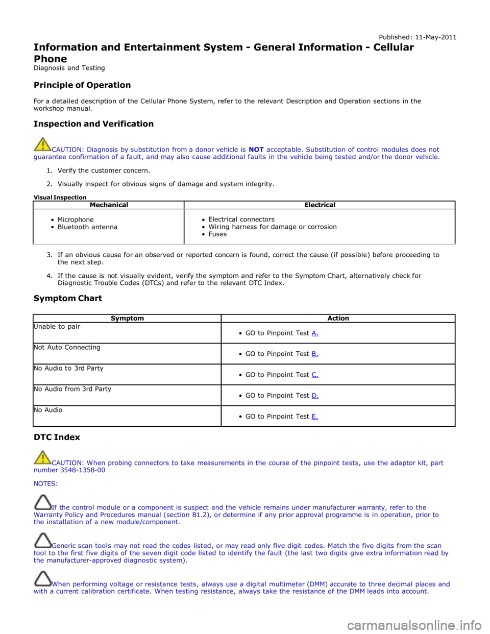
Published: 11-May-2011
Information and Entertainment System - General Information - Cellular
Phone
Diagnosis and Testing
Principle of Operation
For a detailed description of the Cellular Phone System, refer to the relevant Description and Operation sections in the
workshop manual.
Inspection and Verification
CAUTION: Diagnosis by substitution from a donor vehicle is NOT acceptable. Substitution of control modules does not
guarantee confirmation of a fault, and may also cause additional faults in the vehicle being tested and/or the donor vehicle.
1. Verify the customer concern.
2. Visually inspect for obvious signs of damage and system integrity.
Visual Inspection
Mechanical Electrical
Microphone
Bluetooth antenna
Electrical connectors
Wiring harness for damage or corrosion
Fuses
3. If an obvious cause for an observed or reported concern is found, correct the cause (if possible) before proceeding to
the next step.
4. If the cause is not visually evident, verify the symptom and refer to the Symptom Chart, alternatively check for
Diagnostic Trouble Codes (DTCs) and refer to the relevant DTC Index.
Symptom Chart
Symptom Action Unable to pair
GO to Pinpoint Test A. Not Auto Connecting
GO to Pinpoint Test B. No Audio to 3rd Party
GO to Pinpoint Test C. No Audio from 3rd Party
GO to Pinpoint Test D. No Audio
GO to Pinpoint Test E. DTC Index
CAUTION: When probing connectors to take measurements in the course of the pinpoint tests, use the adaptor kit, part
number 3548-1358-00
NOTES:
If the control module or a component is suspect and the vehicle remains under manufacturer warranty, refer to the
Warranty Policy and Procedures manual (section B1.2), or determine if any prior approval programme is in operation, prior to
the installation of a new module/component.
Generic scan tools may not read the codes listed, or may read only five digit codes. Match the five digits from the scan
tool to the first five digits of the seven digit code listed to identify the fault (the last two digits give extra information read by
the manufacturer-approved diagnostic system).
When performing voltage or resistance tests, always use a digital multimeter (DMM) accurate to three decimal places and
with a current calibration certificate. When testing resistance, always take the resistance of the DMM leads into account.
Page 1935 of 3039
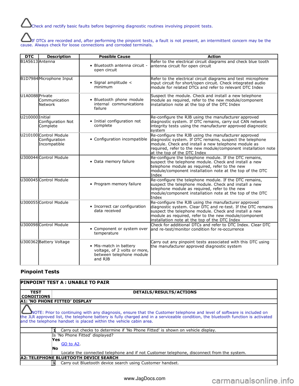
Check and rectify basic faults before beginning diagnostic routines involving pinpoint tests.
If DTCs are recorded and, after performing the pinpoint tests, a fault is not present, an intermittent concern may be the
cause. Always check for loose connections and corroded terminals.
DTC Description Possible Cause Action B1A5613 Antenna
Bluetooth antenna circuit -
open circuit Refer to the electrical circuit diagrams and check blue tooth
antenna circuit for open circuit B1D7984 Microphone Input
Signal amplitude <
minimum Refer to the electrical circuit diagrams and test microphone
input circuit for short/open circuit. Check integrated audio
module for related DTCs and refer to relevant DTC Index U1A0088
Private
Communication
Network
Bluetooth phone module
internal communications
failure Suspect the module. Check and install a new telephone
module as required, refer to the new module/component
installation note at the top of the DTC Index U210000
Initial
Configuration Not
Complete
Initial configuration not
complete Re-configure the RJB using the manufacturer approved
diagnostic system. If DTC remains, carry out CAN network
integrity tests using the manufacturer approved diagnostic system U210100
Control Module
Configuration
Incompatible
Configuration incompatible Re-configure the RJB using the manufacturer approved
diagnostic system. If DTC remains, suspect the telephone
module. Check and install a new telephone module as
required, refer to the new module/component installation note
at the top of the DTC Index U300044 Control Module
Data memory failure Re-configure the telephone module. If the DTC remains,
suspect the telephone module. Check and install a new
telephone module as required, refer to the new
module/component installation note at the top of the DTC
Index U300045 Control Module
Program memory failure Re-configure the telephone module. If the DTC remains,
suspect the telephone module. Check and install a new
telephone module as required, refer to the new
module/component installation note at the top of the DTC
Index U300055 Control Module
Incorrect car configuration
data received Re-configure the RJB using the manufacturer approved
diagnostic system. Clear DTC and re-test. If the DTC remains
suspect the telephone module. Check and install a new
module as required, refer to the new module/component
installation note at the top of the DTC Index U300098 Control Module
Component or system over
temperature Check for additional DTCs and refer to DTC Index. Clear DTC
and re-test/monitor condition for re-occurrence U300362 Battery Voltage
Mis-match in battery
voltage, of 2 volts or more,
between telephone module
and RJB Carry out any pinpoint tests associated with this DTC using
the manufacturer approved diagnostic system
Pinpoint Tests
PINPOINT TEST A : UNABLE TO PAIR TEST
CONDITIONS DETAILS/RESULTS/ACTIONS A1: 'NO PHONE FITTED' DISPLAY
NOTE: Prior to continuing with any diagnosis, ensure that the Customer telephone and level of software is included on
the JLR approved list, the telephone battery is fully charged and in a serviceable condition, the bluetooth function is activated
and the telephone handset is placed within the vehicle cabin area. 1 Carry out checks to determine if 'No Phone Fitted' is shown on vehicle display. Is 'No Phone Fitted' displayed? Yes
GO to A2. No
Locate the connected telephone and if not Customer telephone, disconnect from the system. A2: TELEPHONE BLUETOOTH DEVICE SEARCH 1 Carry out Bluetooth device search using Customer handset. www.JagDocs.com
Page 1936 of 3039
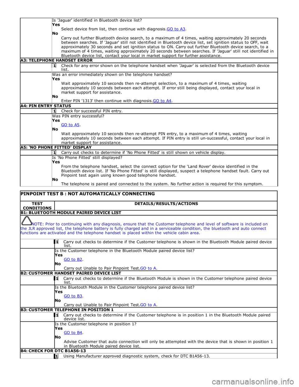
Is 'Jaguar' identified in Bluetooth device list? Yes
Select device from list, then continue with diagnosis.GO to A3. No
Carry out further Bluetooth device search, to a maximum of 4 times, waiting approximately 20 seconds
between searches. If 'Jaguar' still not identified in Bluetooth device list, set ignition status to OFF, wait
approximately 30 seconds and set ignition status to ON. Carry out further Bluetooth device search, to a
maximum of 4 times, waiting approximately 20 seconds between searches. If 'Jaguar' still not identified in
Bluetooth device list, contact your local in market support for further assistance. A3: TELEPHONE HANDSET ERROR 1 Check for any error shown on the telephone handset when 'Jaguar' is selected from the Bluetooth device list. Was an error immediately shown on the telephone handset? Yes
Wait approximately 10 seconds then re-attempt selection, to a maximum of 4 times, waiting
approximately 10 seconds between each attempt. If error still being displayed, contact your local in
market support for assistance.
No
Enter PIN '1313' then continue with diagnosis.GO to A4. A4: PIN ENTRY STATUS 1 Check for successful PIN entry. Was PIN entry successful? Yes
GO to A5. No
Wait approximately 10 seconds then re-attempt PIN entry, to a maximum of 4 times, waiting
approximately 10 seconds between each attempt. If PIN entry is still un-successful, contact your local in
market support for assistance. A5: 'NO PHONE FITTED' DISPLAY 1 Carry out checks to determine if 'No Phone Fitted' is still shown on vehicle display. Is 'No Phone Fitted' still displayed? Yes
From the telephone handset, select the connect option for the 'Land Rover' device identified in the
Bluetooth device list. If 'No Phone Fitted' is still displayed, suspect a telephone handset fault. Carry out
Pinpoint test again using known good telephone handset.
No
The telephone is paired and connected to the system. No further action is required for this symptom.
PINPOINT TEST B : NOT AUTOMATICALLY CONNECTING TEST
CONDITIONS DETAILS/RESULTS/ACTIONS B1: BLUETOOTH MODULE PAIRED DEVICE LIST
NOTE: Prior to continuing with any diagnosis, ensure that the Customer telephone and level of software is included on
the JLR approved list, the telephone battery is fully charged and in a serviceable condition, the bluetooth and auto connect
functions are activated and the telephone handset is placed within the vehicle cabin area. 1 Carry out checks to determine if the Customer telephone is shown in the Bluetooth Module paired device list. Is the Customer telephone in the Bluetooth Module paired device list?
Yes
GO to B2. No
Carry out Unable to Pair Pinpoint Test.GO to A. B2: CUSTOMER HANDSET PAIRED DEVICE LIST 1 Carry out checks to determine if the Bluetooth Module is shown in the Customer telephone paired device list. Is the Bluetooth Module in the Customer telephone paired device list?
Yes
GO to B3. No
Carry out Unable to Pair Pinpoint Test.GO to A. B3: CUSTOMER TELEPHONE IN POSITION 1 1 Carry out checks to determine if the Customer telephone is in position 1 in the Bluetooth Module paired device list. Is the Customer telephone in position 1?
Yes
GO to B4. No
Advise Customer that auto connection will only be attempted with the device that is shown in position 1
in Bluetooth Module paired device list. B4: CHECK FOR DTC B1A56-13 1 Using Manufacturer approved diagnostic system, check for DTC B1A56-13.
Page 1937 of 3039
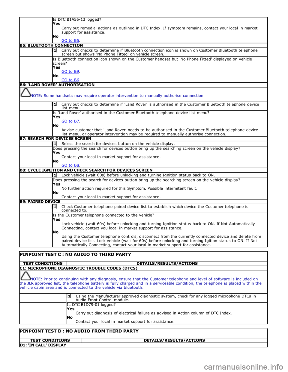
Is DTC B1A56-13 logged?
Yes
Carry out remedial actions as outlined in DTC Index. If symptom remains, contact your local in market
support for assistance.
No
GO to B5. B5: BLUETOOTH CONNECTION 1 Carry out checks to determine if Bluetooth connection icon is shown on Customer Bluetooth telephone screen but shows 'No Phone Fitted' on vehicle screen. Is Bluetooth connection icon shown on the Customer handset but 'No Phone Fitted' displayed on vehicle
screen?
Yes
GO to B9. No
GO to B6. B6: 'LAND ROVER' AUTHORISATION
NOTE: Some handsets may require operator intervention to manually authorise connection. 1 Carry out checks to determine if 'Land Rover' is authorised in the Customer Bluetooth telephone device list menu. Is 'Land Rover' authorised in the Customer Bluetooth telephone device list menu?
Yes
GO to B7. No
Advise customer that 'Land Rover' needs to be authorised in the Customer Bluetooth telephone device
list menu, or operator intervention may be required to manually authorise connection. B7: SEARCH FOR DEVICES SCREEN 1 Select the search for devices button on the vehicle display. Does pressing the search for devices button bring up the searching screen on the vehicle display?
Yes
Contact your local in market support for assistance.
No
GO to B8. B8: CYCLE IGNITION AND CHECK SEARCH FOR DEVICES SCREEN 1 Lock vehicle (wait 60s) before unlocking and turning Ignition status back to ON. Does pressing the search for devices button bring up the searching screen on the vehicle display?
Yes
No further action required for this Symptom. Possible intermitent fault.
No
Contact your local in market support for assistance. B9: PAIRED DEVICE 1 Check Customer telephone paired device list to establish which device the Customer telephone is connected to. Is the Customer telephone connected to the vehicle?
Yes
Lock vehicle (wait 60s) before unlocking and turning Ignition status back to ON. If Not Automatically
Connecting, contact you local in market support for assistance.
No
Using the Customer telephone controls, disconnect from the currently connected device and delete from
paired device list. Lock vehicle (wait for 60s) before unlocking and turning Igition status to ON. If Not Automatically Connecting, contact your local in market support for assistance.
PINPOINT TEST C : NO AUDIO TO THIRD PARTY TEST CONDITIONS DETAILS/RESULTS/ACTIONS C1: MICROPHONE DIAGNOSTIC TROUBLE CODES (DTCS)
NOTE: Prior to continuing with any diagnosis, ensure that the Customer telephone and level of software is included on
the JLR approved list, the telephone battery is fully charged and in a serviceable condition, the telephone is placed within the
vehicle cabin area and is connected to the vehicle via bluetooth. 1 Using the Manufacturer approved diagnostic system, check for any logged microphone DTCs in Audio Front Control module. Is DTC B1D79-01 logged? Yes
Carry out diagnosis of electrical failure as advised in Action column of DTC Index.
No
Contact your local in market support for assistance.
PINPOINT TEST D : NO AUDIO FROM THIRD PARTY TEST CONDITIONS DETAILS/RESULTS/ACTIONS D1: 'IN CALL' DISPLAY
Page 1938 of 3039
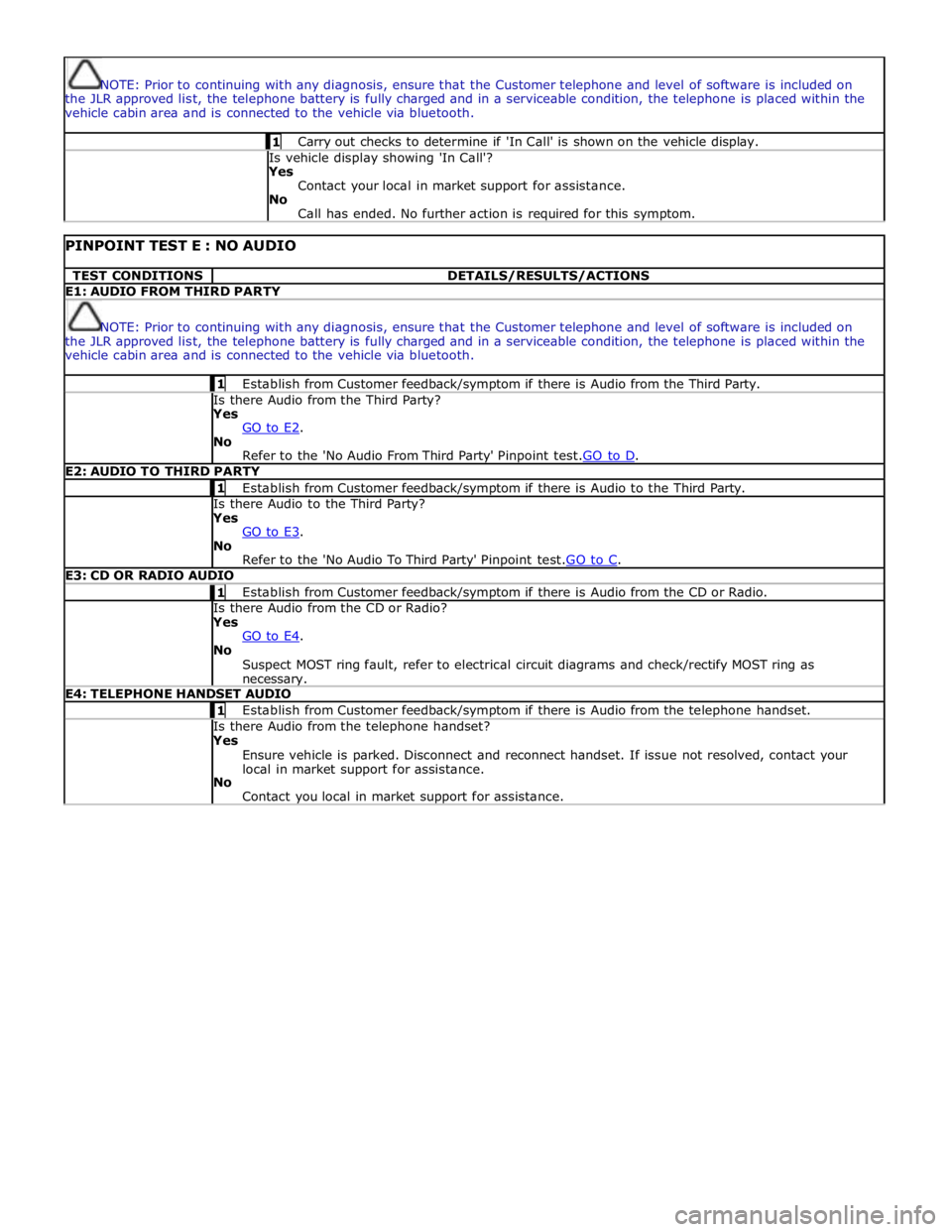
NOTE: Prior to continuing with any diagnosis, ensure that the Customer telephone and level of software is included on
the JLR approved list, the telephone battery is fully charged and in a serviceable condition, the telephone is placed within the
vehicle cabin area and is connected to the vehicle via bluetooth. 1 Carry out checks to determine if 'In Call' is shown on the vehicle display. Is vehicle display showing 'In Call'?
Yes
Contact your local in market support for assistance.
No
Call has ended. No further action is required for this symptom.
PINPOINT TEST E : NO AUDIO TEST CONDITIONS DETAILS/RESULTS/ACTIONS E1: AUDIO FROM THIRD PARTY
NOTE: Prior to continuing with any diagnosis, ensure that the Customer telephone and level of software is included on
the JLR approved list, the telephone battery is fully charged and in a serviceable condition, the telephone is placed within the
vehicle cabin area and is connected to the vehicle via bluetooth. 1 Establish from Customer feedback/symptom if there is Audio from the Third Party. Is there Audio from the Third Party? Yes
GO to E2. No
Refer to the 'No Audio From Third Party' Pinpoint test.GO to D. E2: AUDIO TO THIRD PARTY 1 Establish from Customer feedback/symptom if there is Audio to the Third Party. Is there Audio to the Third Party? Yes
GO to E3. No
Refer to the 'No Audio To Third Party' Pinpoint test.GO to C. E3: CD OR RADIO AUDIO 1 Establish from Customer feedback/symptom if there is Audio from the CD or Radio. Is there Audio from the CD or Radio? Yes
GO to E4. No
Suspect MOST ring fault, refer to electrical circuit diagrams and check/rectify MOST ring as necessary. E4: TELEPHONE HANDSET AUDIO 1 Establish from Customer feedback/symptom if there is Audio from the telephone handset. Is there Audio from the telephone handset? Yes
Ensure vehicle is parked. Disconnect and reconnect handset. If issue not resolved, contact your
local in market support for assistance.
No
Contact you local in market support for assistance.
Page 1966 of 3039
Publi s hed: 11-May-2011
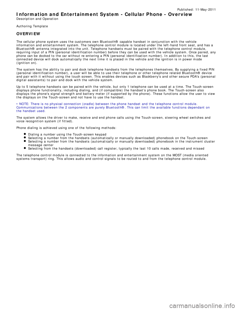
Information and Entertainment System - Cellular Phone - Overview
Des cript ion and Operat ion
Authori ng Templat e
OVERVIEW
The cel lul ar phone s yst em us es t he cus t omers own Bluetooth® capabl e hands et in conjuncti on wit h t he vehicle
informat ion and ent ertai nment sys tem. The t elephone cont rol module i s l ocated under t he left -hand front s eat, and has a
Bluet oot h® ant enna integrat ed i nt o t he unit . Tel ephone handset s mus t be paired wit h t he t el ephone control modul e,
requiring i nput of a PIN (pers onal i dent ificati on number) before t hey can be us ed wi th the vehicle sys tem. Once pai red, any
phone can be docked to the car wi thout re-ent eri ng a PIN (pers onal identi fi cat ion number). In addit ion t o t hi s , the l ast
connected device wi ll dock aut omati cal ly t he next ti me i t is pl aced i n t he vehi cl e a nd t he ignit ion i s i n power mode
(ignit ion on).
The s ys t em has t he abil it y to pai r and dock t elephone hands ets from t he tel ephones t hems elves . By s uppl yi ng a fixed PIN
(personal identi fi cat ion number), a us er wil l be abl e t o us e t hei r tel ephone or othe r t el ephone related Bluetooth® device
and pair wi th i t wit hout us i ng the touch s creen. This enables devices s uch as Blackberry's and ot her s ecure PDA's (pers onal
digit al ass i st ants ) t o pair and dock wit h t he vehi cl e s ys t em.
Up t o 5 telephone hands ets can be pai red wi th the vehicle, but only 1 tel ephone can be us ed at a t ime. The Touch-screen
dis plays phone functi onali ty, i ncl udi ng diali ng, and (if compati ble) t he hands et’s phone book. The Touch-s creen als o
dis plays t he phone's si gnal s trengt h and bat tery meter (if s upported by the phone). These functi ons al low the us er to vi ew
t he dis plays on t he Touch-s creen and not have to us e the handset .
• NOTE: There i s no physi cal connecti on (cradl e) bet ween t he phone hands et and the t elephone cont rol module.
Communicati ons bet ween t he 2 component s are purely Bl uet oot h®. This can l imi t t he avai lable funct ions dependant on
t he hands et used.
The s ys t em al lows t he dri ver t o make, receive and end phone cal ls us ing the Touch-s creen, s t eering wheel s wit ches and
voice recogni ti on s yst em (if fit t ed).
Phone di ali ng is achieved usi ng one of the foll owing met hods :
Dial ing a number us ing t he Touch-screen keypadSelecti ng a number from t he hands ets (aut omat icall y or manual ly downl oaded) phonebook on the Touch-s creenSelecti ng a number from t he hands ets (aut omat icall y or manual ly downl oaded) phonebook in t he i ns t rument clus ter
mes s age centerSelecti ng from t he hands et s (downloaded) cal l regis ter, typicall y the las t 10 cal ls made, received and mis s edThe t el ephone control modul e is connect ed t o t he informati on and entertainment s ys te m on the MOST (medi a oriented
s ys t ems t rans port) ring. This al lows audio and control si gnal s t o be rout ed t o and from t he t elephone control modul e.