2010 JAGUAR XFR Subframe
[x] Cancel search: SubframePage 32 of 3039

Removal and InstallationBack Panel
Quarter Panel
Quarter Panel Lower Extension
Rear Bumper Mounting
Rear Floor Side Extension
Rear Side Member Closing Panel Section
Rear Side Member Section
Rear Wheelhouse Outer
Spare Wheel Well502: Frame and Mounting
502-00: Uni-Body, Subframe and Mounting SystemSpecificationRemoval and InstallationFront Subframe - V8 5.0L Petrol/V8 S/C 5.0L Petrol
Rear Subframe - V8 5.0L Petrol/V8 S/C 5.0L Petrol
Rear Subframe Rear Bushing (64.25.36) - TDV6 3.0L Diesel /V8 5.0L Petrol/V8 S/C 5.0L Petrol
Page 295 of 3039

Jacking and Lifting - Lifting
Description and Operation
Lifting Points—Twin-Post Hoist and Floor Jack
CAUTIONS: Published: 11-May-2011
Do not allow the hoist adapters to contact the steering linkage, suspension arms, stabilizer bar, rear subframe stabilizer
brackets or to compress the lower suspension arm stabilizer bar insulator. Damage to the suspension, exhaust and steering
linkage components may occur if care is not exercised when positioning the hoist adapters of two-post hoists prior to lifting
the vehicle.
Never use the differential housing as a lift point. Damage to the differential housing and cover may occur.
When using a floor jack, a cushioned pad must be utilized to avoid body damage.
Page 300 of 3039

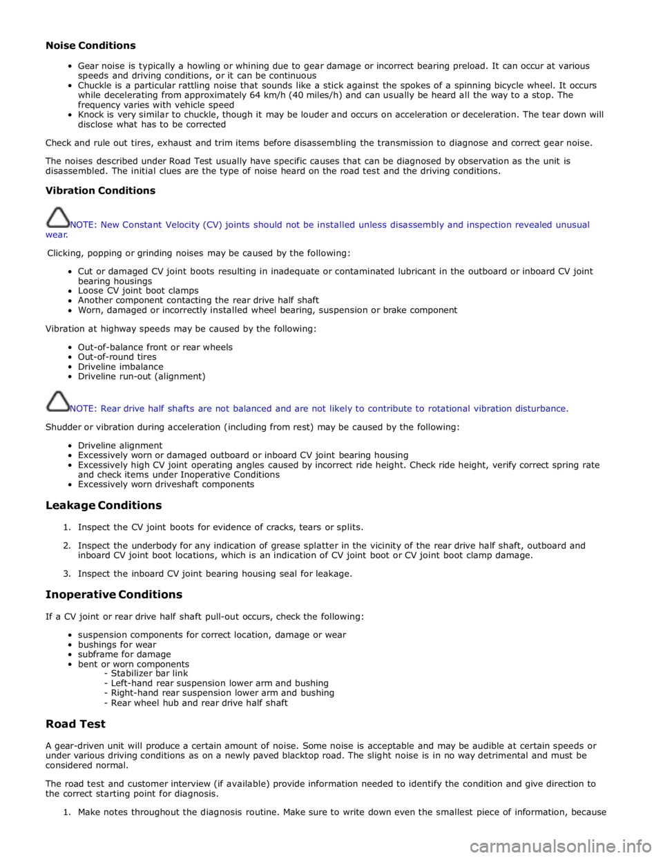
Noise Conditions
Gear noise is typically a howling or whining due to gear damage or incorrect bearing preload. It can occur at various
speeds and driving conditions, or it can be continuous
Chuckle is a particular rattling noise that sounds like a stick against the spokes of a spinning bicycle wheel. It occurs
while decelerating from approximately 64 km/h (40 miles/h) and can usually be heard all the way to a stop. The
frequency varies with vehicle speed
Knock is very similar to chuckle, though it may be louder and occurs on acceleration or deceleration. The tear down will
disclose what has to be corrected
Check and rule out tires, exhaust and trim items before disassembling the transmission to diagnose and correct gear noise.
The noises described under Road Test usually have specific causes that can be diagnosed by observation as the unit is
disassembled. The initial clues are the type of noise heard on the road test and the driving conditions.
Vibration Conditions
wear. NOTE: New Constant Velocity (CV) joints should not be installed unless disassembly and inspection revealed unusual
Clicking, popping or grinding noises may be caused by the following:
Cut or damaged CV joint boots resulting in inadequate or contaminated lubricant in the outboard or inboard CV joint
bearing housings
Loose CV joint boot clamps
Another component contacting the rear drive half shaft
Worn, damaged or incorrectly installed wheel bearing, suspension or brake component
Vibration at highway speeds may be caused by the following:
Out-of-balance front or rear wheels
Out-of-round tires
Driveline imbalance
Driveline run-out (alignment)
NOTE: Rear drive half shafts are not balanced and are not likely to contribute to rotational vibration disturbance.
Shudder or vibration during acceleration (including from rest) may be caused by the following:
Driveline alignment
Excessively worn or damaged outboard or inboard CV joint bearing housing
Excessively high CV joint operating angles caused by incorrect ride height. Check ride height, verify correct spring rate
and check items under Inoperative Conditions
Excessively worn driveshaft components
Leakage Conditions
1. Inspect the CV joint boots for evidence of cracks, tears or splits.
2. Inspect the underbody for any indication of grease splatter in the vicinity of the rear drive half shaft, outboard and
inboard CV joint boot locations, which is an indication of CV joint boot or CV joint boot clamp damage.
3. Inspect the inboard CV joint bearing housing seal for leakage.
Inoperative Conditions
If a CV joint or rear drive half shaft pull-out occurs, check the following:
suspension components for correct location, damage or wear
bushings for wear
subframe for damage
bent or worn components
- Stabilizer bar link
- Left-hand rear suspension lower arm and bushing
- Right-hand rear suspension lower arm and bushing
- Rear wheel hub and rear drive half shaft
Road Test
A gear-driven unit will produce a certain amount of noise. Some noise is acceptable and may be audible at certain speeds or
under various driving conditions as on a newly paved blacktop road. The slight noise is in no way detrimental and must be
considered normal.
The road test and customer interview (if available) provide information needed to identify the condition and give direction to
the correct starting point for diagnosis.
1. Make notes throughout the diagnosis routine. Make sure to write down even the smallest piece of information, because
Page 328 of 3039

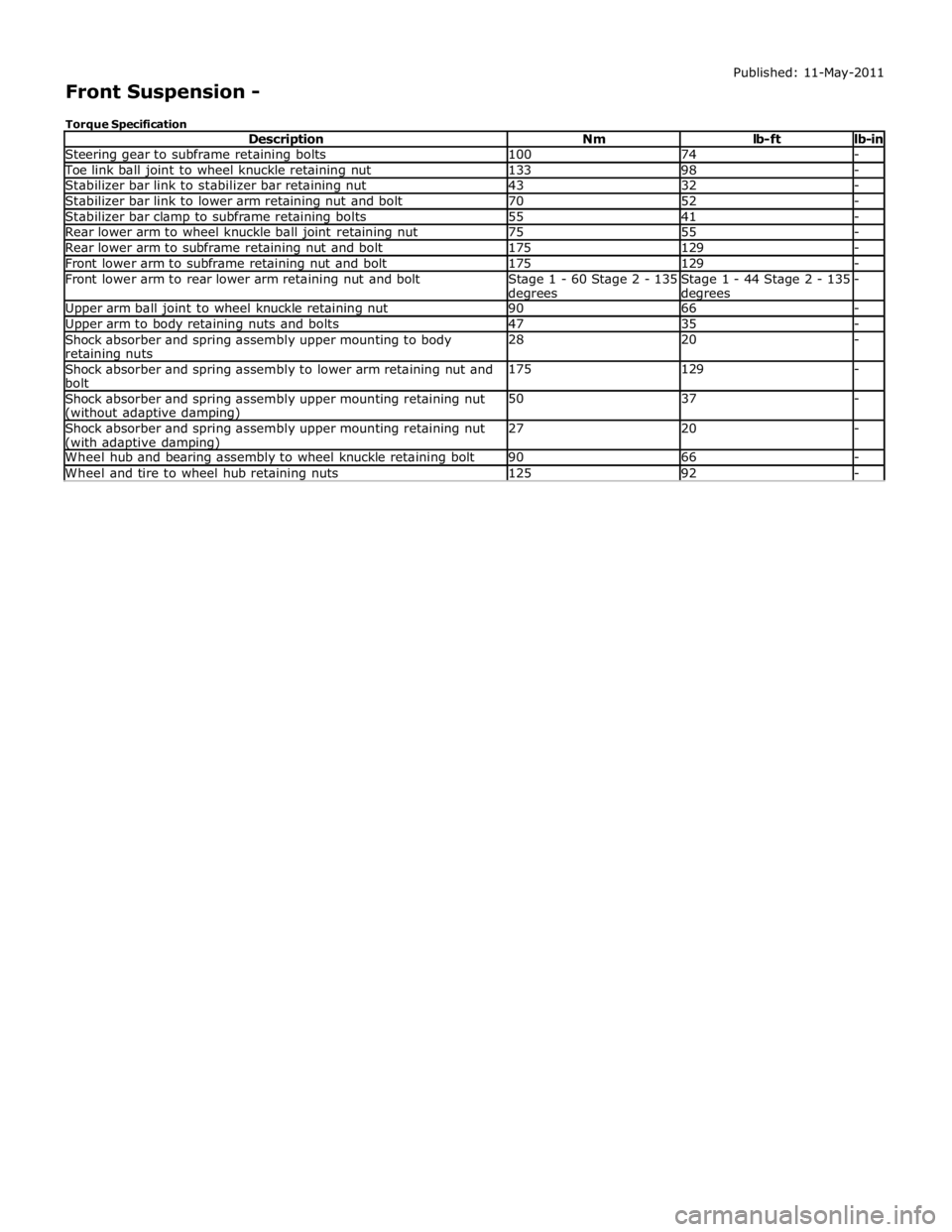
Steering gear to subframe retaining bolts 100 74 - Toe link ball joint to wheel knuckle retaining nut 133 98 - Stabilizer bar link to stabilizer bar retaining nut 43 32 - Stabilizer bar link to lower arm retaining nut and bolt 70 52 - Stabilizer bar clamp to subframe retaining bolts 55 41 - Rear lower arm to wheel knuckle ball joint retaining nut 75 55 - Rear lower arm to subframe retaining nut and bolt 175 129 - Front lower arm to subframe retaining nut and bolt 175 129 - Front lower arm to rear lower arm retaining nut and bolt
Stage 1 - 60 Stage 2 - 135 degrees Stage 1 - 44 Stage 2 - 135 degrees - Upper arm ball joint to wheel knuckle retaining nut 90 66 - Upper arm to body retaining nuts and bolts 47 35 - Shock absorber and spring assembly upper mounting to body retaining nuts 28 20 - Shock absorber and spring assembly to lower arm retaining nut and
bolt 175 129 - Shock absorber and spring assembly upper mounting retaining nut (without adaptive damping) 50 37 - Shock absorber and spring assembly upper mounting retaining nut (with adaptive damping) 27 20 - Wheel hub and bearing assembly to wheel knuckle retaining bolt 90 66 - Wheel and tire to wheel hub retaining nuts 125 92 -
Page 329 of 3039

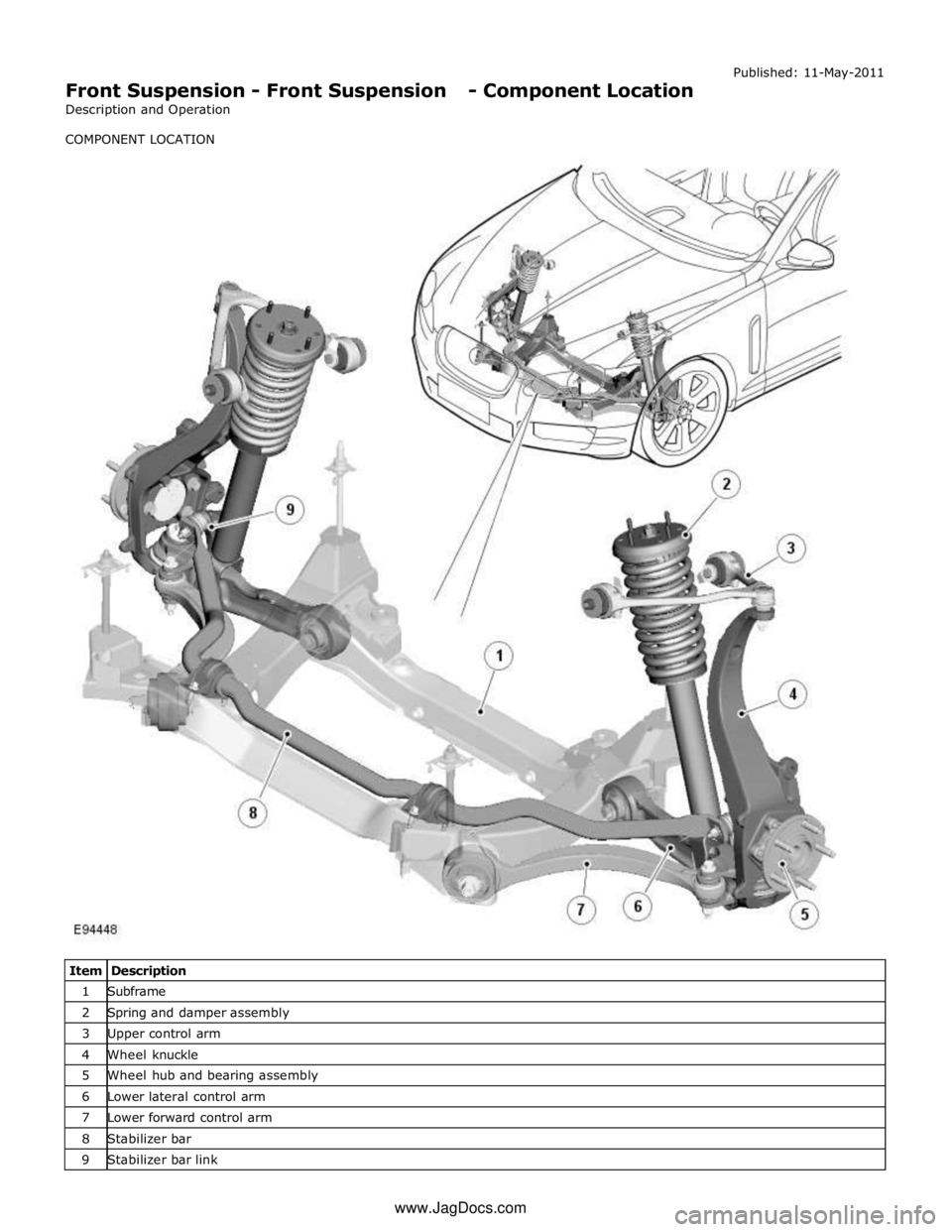
Front Suspension - Front Suspension - Component Location
Description and Operation
COMPONENT LOCATION Published: 11-May-2011
Item Description 1 Subframe 2 Spring and damper assembly 3 Upper control arm 4 Wheel knuckle 5 Wheel hub and bearing assembly 6 Lower lateral control arm 7 Lower forward control arm 8 Stabilizer bar 9 Stabilizer bar link www.JagDocs.com
Page 331 of 3039

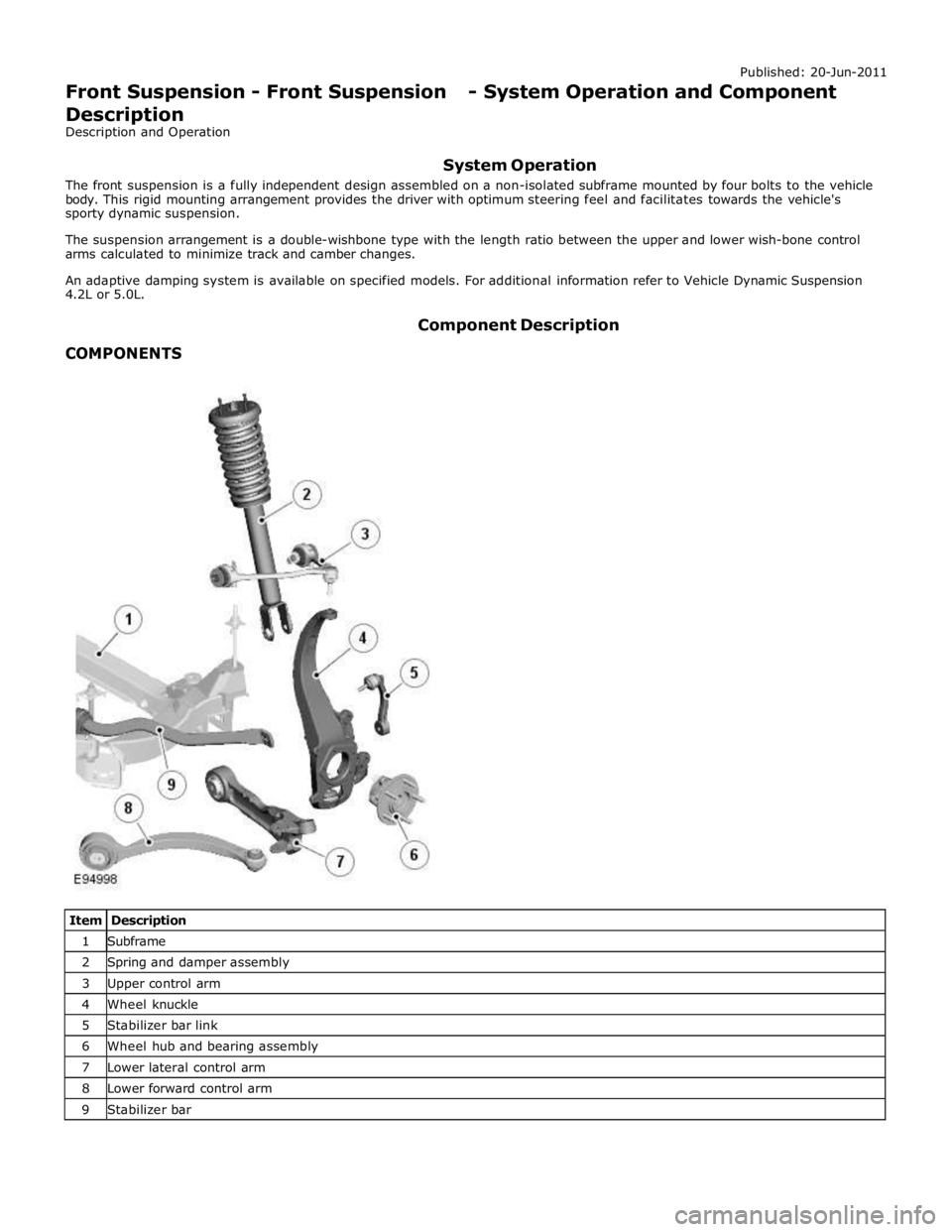
1 Subframe 2 Spring and damper assembly 3 Upper control arm 4 Wheel knuckle 5 Stabilizer bar link 6 Wheel hub and bearing assembly 7 Lower lateral control arm 8 Lower forward control arm 9 Stabilizer bar
Page 332 of 3039

Upper Control Arm
The forged-aluminum upper control arm is a wishbone design and connects to the vehicle body through two plain bushes, and
links to the swan neck wheel knuckle by an integral ball joint. The upper control arm is inclined to provide anti-dive
characteristics under heavy braking, while also controlling geometry for vehicle straight-line stability.
Lower Control Arm
The forged aluminum lower control arms are of the wishbone design; the arms separate to allow for optimum bush tuning:
The rear lateral control arm is fitted with a bush at its inner end which locates between brackets on the subframe. The
arm is secured with an eccentric bolt which provides the adjustment of the suspension camber geometry. The outer end
of the control arm has a tapered hole which locates on a ball joint fitted to the wheel knuckle. An integral clevis bracket
on the forward face of the lateral control arm allows for the attachment of the forward control arm. A bush is fitted
below the clevis bracket to provide for the attachment of the stabilizer bar link. A cross-axis joint is fitted to a
cross-hole in the control arm to provide the location for the clevis attachment of the spring and damper assembly.
The forward control arm is fitted with a fluid-block rubber bush at its inner end which locates between brackets on the
subframe. The arm is secured with an eccentric bolt which provides adjustment of the castor and camber geometry. The
outer end of the control arm is fitted with a cross-axis joint and locates in the integral clevis bracket on the lateral
control arm.
Wheel Knuckle
The cast aluminum wheel knuckle is a swan neck design and attaches to the upper control arm and lower lateral control arm.
The lower lateral control arm locates on a non serviceable ball-joint integral with the wheel knuckle. The lower boss on the
rear of the knuckle provides for the attachment of the steering gear tie-rod ball joint.
The wheel knuckle also provides the mounting locations for the:
wheel hub and bearing assembly
the wheel speed sensor (integral to the wheel hub and bearing assembly)
brake caliper and disc shield.
Stabilizer Bar
The stabilizer bar is attached to the front of the subframe with bushes and mounting brackets. The pressed steel mounting
brackets locate over the bushes and are attached to the cross member with bolts screwed into threaded locations in the
subframe. The stabilizer bar has crimped, 'anti-shuffle' collars pressed in position on the inside edges of the bushes. The
collars prevent sideways movement of the stabilizer bar.
The stabilizer bar is manufactured from 32mm diameter tubular steel on supercharged models and 31mm diameter tubular
steel on diesel and normally aspirated models and has been designed to provide particular characteristics in maintaining roll
rates, specifically in primary ride comfort.
Each end of the stabilizer bar curves rearwards to attach to a ball joint on a stabilizer link. Each stabilizer link is secured to a
bush in the lower lateral arm with a bolt and locknut. The links allow the stabilizer bar to move with the wheel travel providing
maximum effectiveness.
The only difference between the front stabilizer bars, in addition to the diameter, is in the shape to accommodate engine
variant:
a slightly curved bar, between bush centers, for V6 diesel (31 mm dia) and V8 gasoline supercharged (32 mm dia),
a straight bar, between bush centers, for V6 and V8 normally aspirated gasoline engines (31 mm dia).
Spring and Damper Assembly
The spring and damper assemblies are located between the lower lateral arm and the front suspension housing in the inner
wing. Dependant on vehicle model there are three types of coil spring and damper available:
a standard oil passive damper (All models except supercharged),
an adaptive damper, also known as Computer Active Technology Suspension (CATS) on 4.2L supercharged vehicles up to
2010MY, For additional information refer to Vehicle Dynamic Suspension 4.2L.
a continuously variable adaptive damper, also known as Adaptive Dynamics System on 5.0L supercharged vehicles from
2010MY. For additional information refer to Vehicle Dynamic Suspension 5.0L.
The dampers are a monotube design with a spring seat secured by a circlip onto the damper tube. The damper's lower
spherical joint is an integral part of the lateral lower control-arm, and the damper takes the form of a clevis-end, which
straddles the spherical joint.
The damper piston is connected to a damper rod which is sealed at its exit point from the damper body. The threaded outer
end of the damper rod locates through a hole in the top mount. A self locking nut secures the top mount to the damper rod.
The damper rod on the adaptive damper has an electrical connector on the outer end of the damper rod.
Supercharged 4.2L vehicles up to 2010MY: The adaptive damper functions by restricting the flow of hydraulic fluid through
internal galleries in the damper's piston. The adaptive damper has a solenoid operated valve, which when switched allows a
greater flow of hydraulic fluid through the damper's piston. This provides a softer damping characteristic from the damper. The
adaptive damper defaults to a firmer setting when not activated. The solenoid is computer controlled and can switch between
soft and hard damping settings depending on road wheel inputs and vehicle speed.
Supercharged 5.0L vehicles from 2010MY: The variable damper functions by adjustment of a solenoid operated variable orifice,
which opens up an alternative path for oil flow within the damper. When de-energized the bypass is closed and all the oil flows
Page 390 of 3039

Halfshaft outer constant velocity joint retaining nut 300 221 - Lower arm to wheel knuckle retaining nut and bolt 190 140 - Lower arm to subframe retaining nut and bolt 192 142 - Lower arm to subframe retaining bolt 192 142 - Upper arm ball joint to wheel knuckle retaining nut 96 71 - Upper arm to subframe retaining nut and bolt 115 85 - Toe link to subframe ball joint retaining nut 90 66 - Toe link to wheel knuckle retaining nut and bolt 63 46 - Toe link setting nut 55 41 - Shock absorber and spring assembly upper mounting to body retaining nuts 28 21 - Shock absorber and spring assembly upper mounting retaining nut (without adaptive damping) 50 37 - Shock absorber and spring assembly upper mounting retaining nut (with adaptive damping) 27 20 - Shock absorber to lower arm retaining bolt 133 98 - Stabilizer bar link to stabilizer bar retaining nut 48 35 - Stabilizer bar clamp to subframe retaining bolt 55 41 - Stabilizer bar link to lower arm retaining nut 48 35 - Wheel and tire to wheel hub retaining nuts 125 92 - www.JagDocs.com