2010 JAGUAR XFR Subframe
[x] Cancel search: SubframePage 1519 of 3039
Published: 11-May-2011
Transmission/Transaxle Cooling - TDV6 3.0L Diesel /V8 5.0L Petrol/V8 S/C 5.0L Petrol - Transmission Cooling - Overview
Description and Operation
OVERVIEW
Transmission cooling is provided by a transmission fluid cooler, which transfers heat from the transmission to the engine
cooling system. The transmission fluid cooler is attached to a mounting bracket on the front subframe, in the front left corner
of the engine compartment.
Two hose and pipe assemblies connect the transmission fluid cooler to the automatic transmission. Two engine coolant hose
connections are incorporated into the top of the transmission fluid cooler for the supply and return of coolant from the engine
cooling system. For additional information, refer to 303-03D Engine Cooling.
Page 2744 of 3039
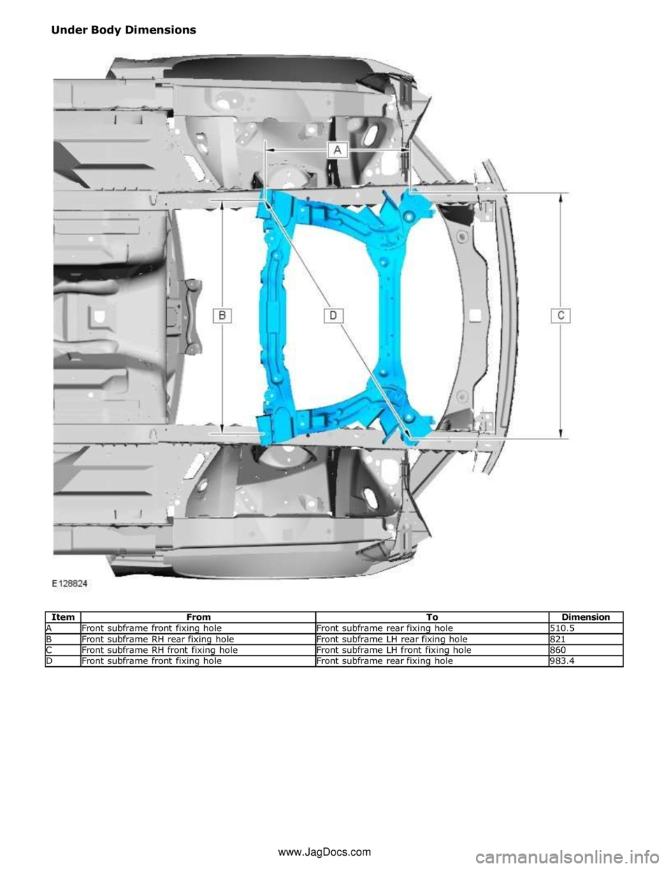
A Front subframe front fixing hole Front subframe rear fixing hole 510.5 B Front subframe RH rear fixing hole Front subframe LH rear fixing hole 821 C Front subframe RH front fixing hole Front subframe LH front fixing hole 860 D Front subframe front fixing hole Front subframe rear fixing hole 983.4 www.JagDocs.com
Page 2745 of 3039
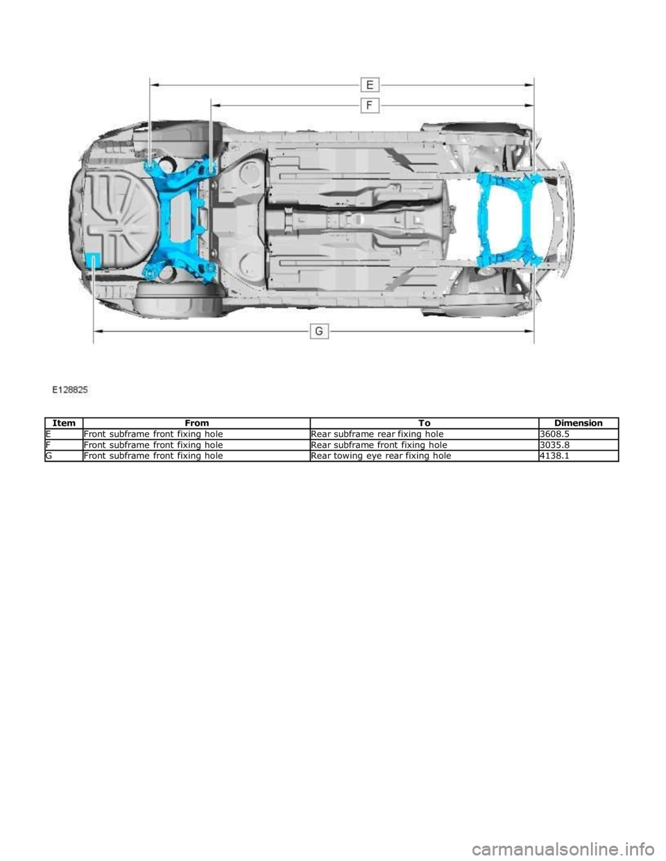
E Front subframe front fixing hole Rear subframe rear fixing hole 3608.5 F Front subframe front fixing hole Rear subframe front fixing hole 3035.8 G Front subframe front fixing hole Rear towing eye rear fixing hole 4138.1
Page 2746 of 3039
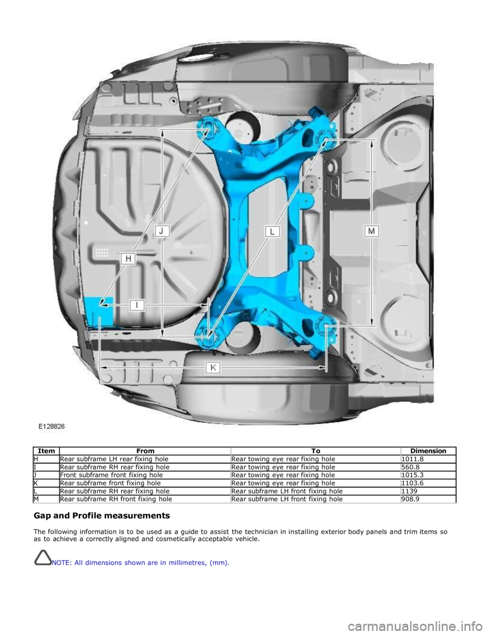
Item From To Dimension H Rear subframe LH rear fixing hole Rear towing eye rear fixing hole 1011.8 I Rear subframe RH rear fixing hole Rear towing eye rear fixing hole 560.8 J Front subframe front fixing hole Rear towing eye rear fixing hole 1015.3 K Rear subframe front fixing hole Rear towing eye rear fixing hole 1103.6 L Rear subframe RH rear fixing hole Rear subframe LH front fixing hole 1139 M Rear subframe RH front fixing hole Rear subframe LH front fixing hole 908.9
Gap and Profile measurements
The following information is to be used as a guide to assist the technician in installing exterior body panels and trim items so
as to achieve a correctly aligned and cosmetically acceptable vehicle.
NOTE: All dimensions shown are in millimetres, (mm).
Page 2784 of 3039
Front End Sheet Metal Repairs - Front Side Member
Removal and Installation
Removal Published: 11-May-2011
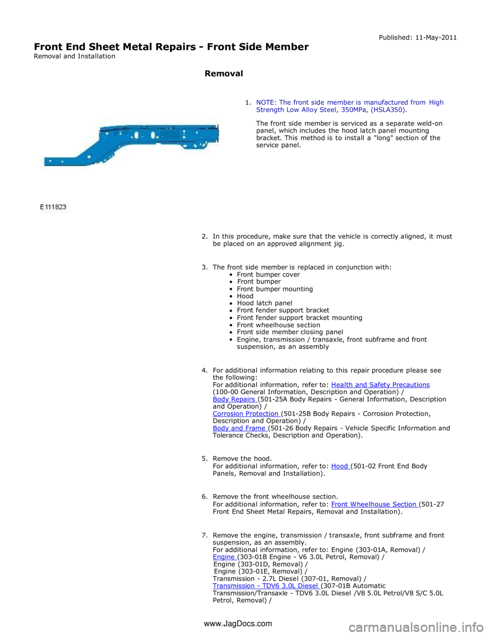
1. NOTE: The front side member is manufactured from High
Strength Low Alloy Steel, 350MPa, (HSLA350).
The front side member is serviced as a separate weld-on
panel, which includes the hood latch panel mounting
bracket. This method is to install a "long" section of the
service panel.
2. In this procedure, make sure that the vehicle is correctly aligned, it must
be placed on an approved alignment jig.
3. The front side member is replaced in conjunction with:
Front bumper cover
Front bumper
Front bumper mounting
Hood
Hood latch panel
Front fender support bracket
Front fender support bracket mounting
Front wheelhouse section
Front side member closing panel
Engine, transmission / transaxle, front subframe and front
suspension, as an assembly
4. For additional information relating to this repair procedure please see
the following:
For additional information, refer to: Health and Safety Precautions (100-00 General Information, Description and Operation) /
Body Repairs (501-25A Body Repairs - General Information, Description and Operation) /
Corrosion Protection (501-25B Body Repairs - Corrosion Protection, Description and Operation) /
Body and Frame (501-26 Body Repairs - Vehicle Specific Information and Tolerance Checks, Description and Operation).
5. Remove the hood.
For additional information, refer to: Hood (501-02 Front End Body Panels, Removal and Installation).
6. Remove the front wheelhouse section.
For additional information, refer to: Front Wheelhouse Section (501-27 Front End Sheet Metal Repairs, Removal and Installation).
7. Remove the engine, transmission / transaxle, front subframe and front
suspension, as an assembly.
For additional information, refer to: Engine (303-01A, Removal) /
Engine (303-01B Engine - V6 3.0L Petrol, Removal) / Engine (303-01D, Removal) /
Engine (303-01E, Removal) /
Transmission - 2.7L Diesel (307-01, Removal) /
Transmission - TDV6 3.0L Diesel (307-01B Automatic Transmission/Transaxle - TDV6 3.0L Diesel /V8 5.0L Petrol/V8 S/C 5.0L
Petrol, Removal) / www.JagDocs.com
Page 2785 of 3039
Transmission (307-01A Automatic Transmission/Transaxle - V6 3.0L Petrol, Removal) /
Transmission - 4.2L (307-01, Removal) /
Transmission - V8 5.0L Petrol/V8 S/C 5.0L Petrol (307-01B Automatic Transmission/Transaxle - TDV6 3.0L Diesel /V8 5.0L Petrol/V8 S/C 5.0L
Petrol, Removal) /
Front Shock Absorber (204-01 Front Suspension, Removal and Installation) /
Front Subframe - 2.7L Diesel (502-00, Removal and Installation) /
Front Subframe - V6 3.0L Petrol (502-00 Uni-Body, Subframe and Mounting System, Removal and Installation) /
Front Subframe - 4.2L, Vehicles Without: Supercharger (502-00, Removal
and Installation) /
Front Subframe - 4.2L, Vehicles With: Supercharger (502-00, Removal
and Installation).
8. Remove the pedestrian protection hood actuator.
For additional information, refer to: Pedestrian Protection Hood Actuator LH (501-20C Pedestrian Protection System, Removal and Installation) / Pedestrian Protection Hood Actuator RH (501-20C Pedestrian Protection System, Removal and Installation).
9. If the drivers side front side member and suspension top mount is to be
repaired, remove the brake master cylinder and reservoir.
For additional information, refer to: Brake Master Cylinder (206-06 Hydraulic Brake Actuation, Removal and Installation) /
Brake Fluid Reservoir (206-06 Hydraulic Brake Actuation, Removal and Installation).
10. If the left-hand front side member and suspension top mount assembly
is to be repaired, remove the fuel supply and return lines.
11. Release and position the front side member wiring harness to one side.
12. Remove any remaining miscellaneous components from the repair area.
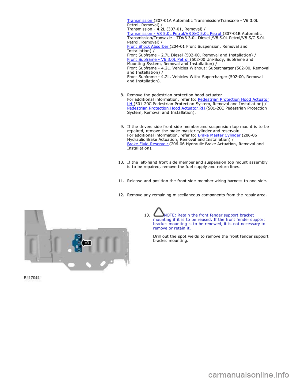
13. NOTE: Retain the front fender support bracket
mounting if it is to be reused. If the front fender support
bracket mounting is to be renewed, it is not necessary to
remove or retain it.
Drill out the spot welds to remove the front fender support
bracket mounting.
Page 2797 of 3039
(100-00 General Information, Description and Operation) /
Body Repairs (501-25A Body Repairs - General Information, Description and Operation) /
Corrosion Protection (501-25B Body Repairs - Corrosion Protection, Description and Operation) /
Body and Frame (501-26 Body Repairs - Vehicle Specific Information and Tolerance Checks, Description and Operation).
5. Remove the fender apron panel front extension.
For additional information, refer to: Fender Apron Panel Front Extension (501-27 Front End Sheet Metal Repairs, Removal and Installation).
6. Remove the front fender support bracket.
For additional information, refer to: Front Fender Support Bracket (501-27 Front End Sheet Metal Repairs, Removal and Installation).
7. Remove the fender apron panel.
For additional information, refer to: Fender Apron Panel (501-27 Front End Sheet Metal Repairs, Removal and Installation).
8. Remove the engine, transmission / transaxle, front subframe and front
suspension, as an assembly.
For additional information, refer to: Engine (303-01A, Removal) /
Engine (303-01B Engine - V6 3.0L Petrol, Removal) / Engine (303-01D, Removal) /
Engine (303-01E, Removal) /
Transmission - 2.7L Diesel (307-01, Removal) /
Transmission - TDV6 3.0L Diesel (307-01B Automatic Transmission/Transaxle - TDV6 3.0L Diesel /V8 5.0L Petrol/V8 S/C 5.0L
Petrol, Removal) /
Transmission (307-01A Automatic Transmission/Transaxle - V6 3.0L Petrol, Removal) /
Transmission - 4.2L (307-01, Removal) /
Transmission - V8 5.0L Petrol/V8 S/C 5.0L Petrol (307-01B Automatic Transmission/Transaxle - TDV6 3.0L Diesel /V8 5.0L Petrol/V8 S/C 5.0L
Petrol, Removal) /
Front Shock Absorber (204-01 Front Suspension, Removal and Installation) /
Front Subframe - 2.7L Diesel (502-00, Removal and Installation) /
Front Subframe - V6 3.0L Petrol (502-00 Uni-Body, Subframe and Mounting System, Removal and Installation) /
Front Subframe - 4.2L, Vehicles Without: Supercharger (502-00, Removal
and Installation) /
Front Subframe - 4.2L, Vehicles With: Supercharger (502-00, Removal
and Installation).
9. Remove the pedestrian protection hood actuator.
For additional information, refer to: Pedestrian Protection Hood Actuator LH (501-20C Pedestrian Protection System, Removal and Installation) / Pedestrian Protection Hood Actuator RH (501-20C Pedestrian Protection System, Removal and Installation).
10. If the drivers side front side member and suspension top mount is to be
repaired, remove the brake master cylinder and reservoir.
For additional information, refer to: Brake Master Cylinder (206-06 Hydraulic Brake Actuation, Removal and Installation) /
Brake Fluid Reservoir (206-06 Hydraulic Brake Actuation, Removal and Installation).
11. If the drivers side front side member and suspension top mount is to be
repaired, remove the brake booster.
Page 2807 of 3039
Published: 11-May-2011
Front End Sheet Metal Repairs - Front Side Member Closing Panel
Removal and Installation
Removal
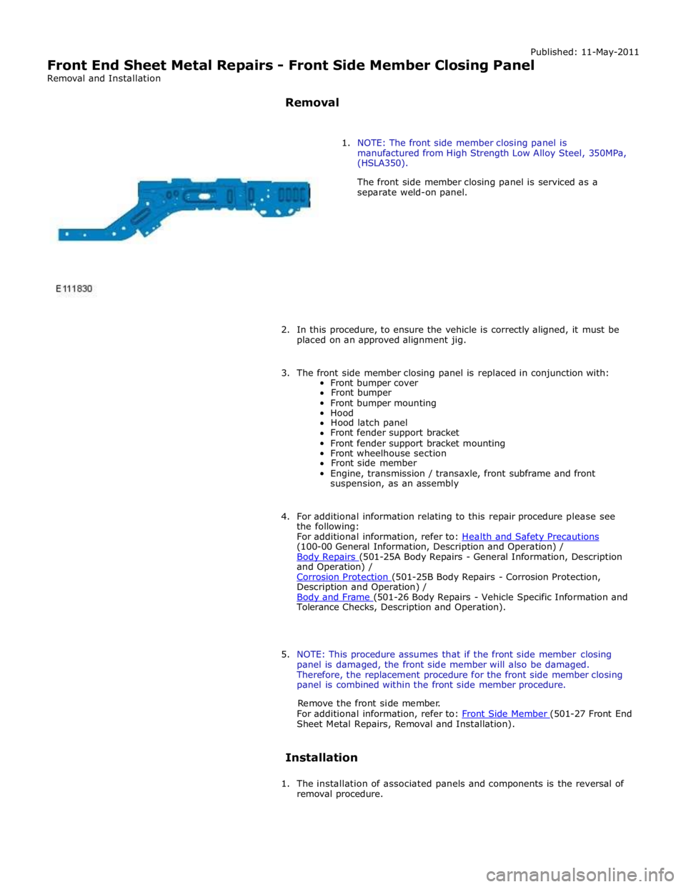
1. NOTE: The front side member closing panel is
manufactured from High Strength Low Alloy Steel, 350MPa,
(HSLA350).
The front side member closing panel is serviced as a
separate weld-on panel.
2. In this procedure, to ensure the vehicle is correctly aligned, it must be
placed on an approved alignment jig.
3. The front side member closing panel is replaced in conjunction with:
Front bumper cover
Front bumper
Front bumper mounting
Hood
Hood latch panel
Front fender support bracket
Front fender support bracket mounting
Front wheelhouse section
Front side member
Engine, transmission / transaxle, front subframe and front
suspension, as an assembly
4. For additional information relating to this repair procedure please see
the following:
For additional information, refer to: Health and Safety Precautions (100-00 General Information, Description and Operation) /
Body Repairs (501-25A Body Repairs - General Information, Description and Operation) /
Corrosion Protection (501-25B Body Repairs - Corrosion Protection, Description and Operation) /
Body and Frame (501-26 Body Repairs - Vehicle Specific Information and Tolerance Checks, Description and Operation).
5. NOTE: This procedure assumes that if the front side member closing
panel is damaged, the front side member will also be damaged.
Therefore, the replacement procedure for the front side member closing
panel is combined within the front side member procedure.
Remove the front side member.
For additional information, refer to: Front Side Member (501-27 Front End Sheet Metal Repairs, Removal and Installation).
Installation
1. The installation of associated panels and components is the reversal of
removal procedure.