2010 JAGUAR XFR Subframe
[x] Cancel search: SubframePage 486 of 3039

2 Main piston 3 Tube 4 Bypass valve (closed) 5 Piston and rod assembly ACCELEROMETERS
Three accelerometers are used in the adaptive dynamics system. The accelerometers are located as follows:
One each on the rear edge of the radiator support panel.
One in the luggage compartment, in the rear LH corner adjacent to the rear lamp assembly.
The accelerometers measure acceleration in the vertical plane and output a corresponding analogue signal to the adaptive
damping module. The algorithms in the adaptive damping module calculate the heave, pitch and roll motions of the vehicle,
which are used by the module to control road induced body modes.
Each accelerometer is connected to the adaptive damping module via three wires, which supply ground, 5 V supply and signal
return.
The sensing element comprises a single parallel plate capacitor, one plate of which moves relative to the other dependant on
the force (acceleration) applied. This causes the capacitance to change as a function of applied acceleration. This capacitance
is compared with a fixed reference capacitor in a bridge circuit and the signal is processed by means of a dedicated integrated
circuit to generate an output voltage that varies as a function of applied acceleration. The sensors output a signal voltage of
approximately 1 V/g ± 0.05 V/g.
SUSPENSION HEIGHT SENSORS
Four suspension height sensors are used in the adaptive dynamics system, two for the front suspension and two for the rear
suspension. A front suspension height sensor is attached to each side of the front subframes and connected by a sensor arm
and sensor link to the related lower lateral arm of the front suspension. A rear suspension height sensor is attached to each
side of the rear subframe and connected by a sensor arm and sensor link to the related upper control arm of the rear
suspension. On each suspension height sensor, the sensor arm and sensor link convert linear movement of the suspension into
rotary movement of the sensor shaft.
The sensors are also used for the static dynamic headlamp leveling system on vehicles fitted with xenon headlamps.
The suspension height sensors measure suspension displacement at each corner of the vehicle and output a corresponding
analogue signal to the adaptive damping module. The algorithms in the adaptive damping module calculate the position,
velocity and frequency content of the signals and use the results for wheel control.
Each suspension height sensor is connected to the adaptive damping module via three wires, which supply ground, 5 V supply
Page 509 of 3039

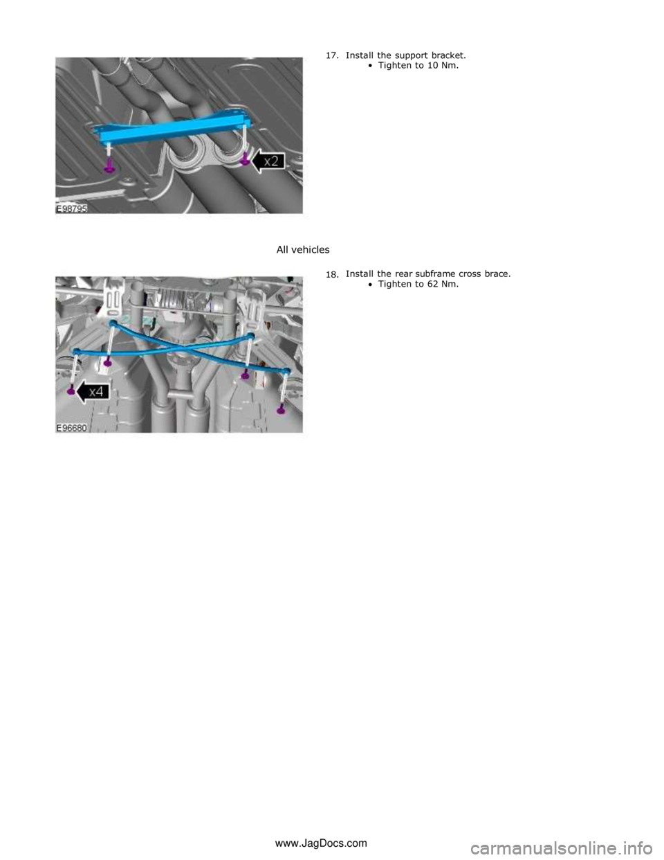
17. Install the support bracket.
Tighten to 10 Nm.
All vehicles
18. Install the rear subframe cross brace.
Tighten to 62 Nm. www.JagDocs.com
Page 585 of 3039

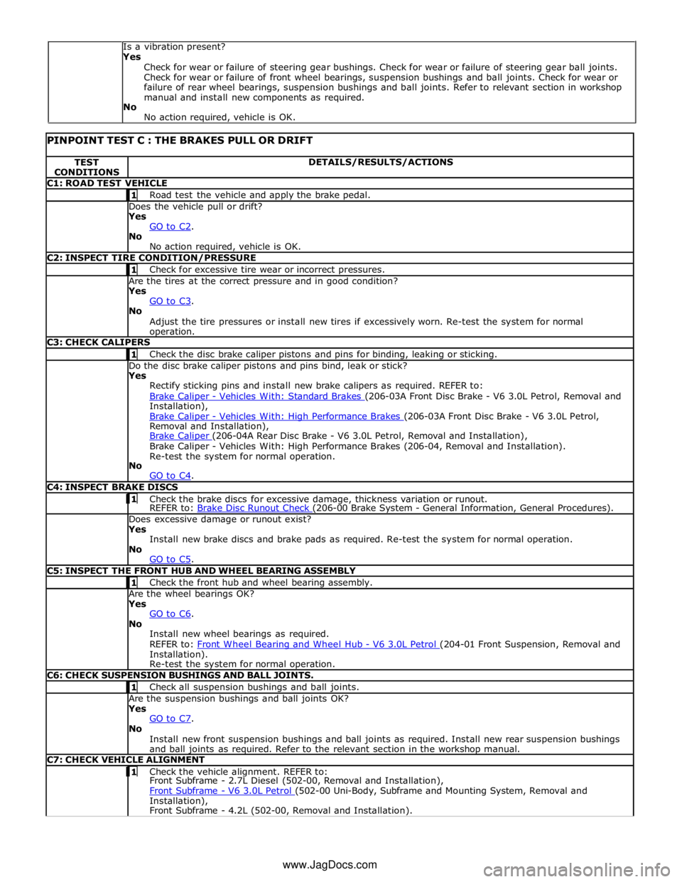
TEST
CONDITIONS DETAILS/RESULTS/ACTIONS C1: ROAD TEST VEHICLE 1 Road test the vehicle and apply the brake pedal. Does the vehicle pull or drift?
Yes
GO to C2. No
No action required, vehicle is OK. C2: INSPECT TIRE CONDITION/PRESSURE 1 Check for excessive tire wear or incorrect pressures. Are the tires at the correct pressure and in good condition?
Yes
GO to C3. No
Adjust the tire pressures or install new tires if excessively worn. Re-test the system for normal operation. C3: CHECK CALIPERS 1 Check the disc brake caliper pistons and pins for binding, leaking or sticking. Do the disc brake caliper pistons and pins bind, leak or stick?
Yes
Rectify sticking pins and install new brake calipers as required. REFER to:
Brake Caliper - Vehicles With: Standard Brakes (206-03A Front Disc Brake - V6 3.0L Petrol, Removal and Installation),
Brake Caliper - Vehicles With: High Performance Brakes (206-03A Front Disc Brake - V6 3.0L Petrol, Removal and Installation),
Brake Caliper (206-04A Rear Disc Brake - V6 3.0L Petrol, Removal and Installation), Brake Caliper - Vehicles With: High Performance Brakes (206-04, Removal and Installation).
Re-test the system for normal operation.
No
GO to C4. C4: INSPECT BRAKE DISCS 1 Check the brake discs for excessive damage, thickness variation or runout. REFER to: Brake Disc Runout Check (206-00 Brake System - General Information, General Procedures). Does excessive damage or runout exist?
Yes
Install new brake discs and brake pads as required. Re-test the system for normal operation.
No
GO to C5. C5: INSPECT THE FRONT HUB AND WHEEL BEARING ASSEMBLY 1 Check the front hub and wheel bearing assembly. Are the wheel bearings OK?
Yes
GO to C6. No
Install new wheel bearings as required.
REFER to: Front Wheel Bearing and Wheel Hub - V6 3.0L Petrol (204-01 Front Suspension, Removal and Installation).
Re-test the system for normal operation. C6: CHECK SUSPENSION BUSHINGS AND BALL JOINTS. 1 Check all suspension bushings and ball joints. Are the suspension bushings and ball joints OK?
Yes
GO to C7. No
Install new front suspension bushings and ball joints as required. Install new rear suspension bushings
and ball joints as required. Refer to the relevant section in the workshop manual. C7: CHECK VEHICLE ALIGNMENT 1 Check the vehicle alignment. REFER to: Front Subframe - 2.7L Diesel (502-00, Removal and Installation),
Front Subframe - V6 3.0L Petrol (502-00 Uni-Body, Subframe and Mounting System, Removal and Installation),
Front Subframe - 4.2L (502-00, Removal and Installation). Is a vibration present?
Yes
Check for wear or failure of steering gear bushings. Check for wear or failure of steering gear ball joints.
Check for wear or failure of front wheel bearings, suspension bushings and ball joints. Check for wear or
failure of rear wheel bearings, suspension bushings and ball joints. Refer to relevant section in workshop
manual and install new components as required.
No
No action required, vehicle is OK.
www.JagDocs.com
Page 586 of 3039

TEST
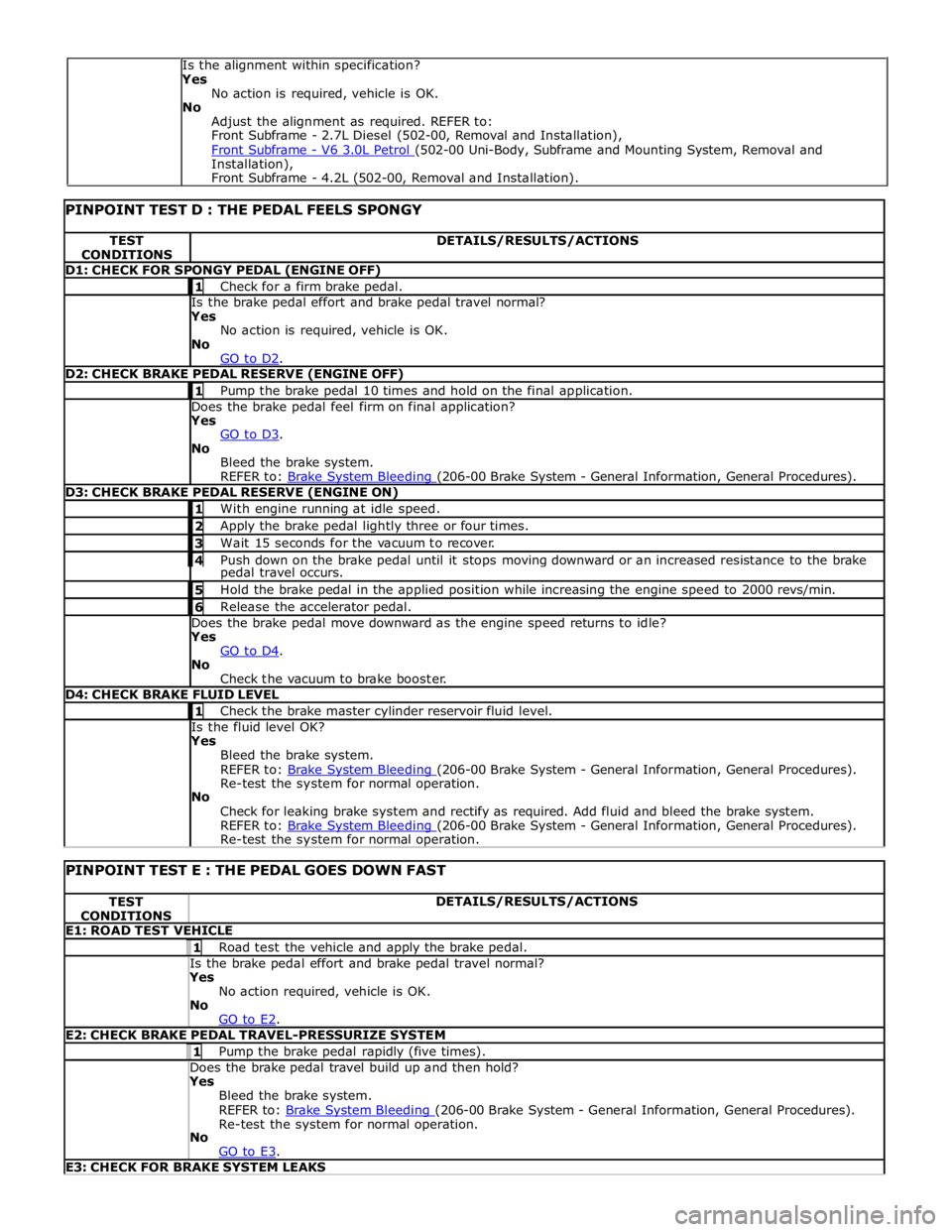
CONDITIONS DETAILS/RESULTS/ACTIONS D1: CHECK FOR SPONGY PEDAL (ENGINE OFF) 1 Check for a firm brake pedal. Is the brake pedal effort and brake pedal travel normal? Yes
No action is required, vehicle is OK.
No
GO to D2. D2: CHECK BRAKE PEDAL RESERVE (ENGINE OFF) 1 Pump the brake pedal 10 times and hold on the final application. Does the brake pedal feel firm on final application? Yes
GO to D3. No
Bleed the brake system.
REFER to: Brake System Bleeding (206-00 Brake System - General Information, General Procedures). D3: CHECK BRAKE PEDAL RESERVE (ENGINE ON) 1 With engine running at idle speed. 2 Apply the brake pedal lightly three or four times. 3 Wait 15 seconds for the vacuum to recover. 4 Push down on the brake pedal until it stops moving downward or an increased resistance to the brake pedal travel occurs. 5 Hold the brake pedal in the applied position while increasing the engine speed to 2000 revs/min. 6 Release the accelerator pedal. Does the brake pedal move downward as the engine speed returns to idle? Yes
GO to D4. No
Check the vacuum to brake booster. D4: CHECK BRAKE FLUID LEVEL 1 Check the brake master cylinder reservoir fluid level. Is the fluid level OK? Yes
Bleed the brake system.
REFER to: Brake System Bleeding (206-00 Brake System - General Information, General Procedures). Re-test the system for normal operation.
No
Check for leaking brake system and rectify as required. Add fluid and bleed the brake system.
REFER to: Brake System Bleeding (206-00 Brake System - General Information, General Procedures). Re-test the system for normal operation.
PINPOINT TEST E : THE PEDAL GOES DOWN FAST TEST
CONDITIONS DETAILS/RESULTS/ACTIONS E1: ROAD TEST VEHICLE 1 Road test the vehicle and apply the brake pedal. Is the brake pedal effort and brake pedal travel normal? Yes
No action required, vehicle is OK.
No
GO to E2. E2: CHECK BRAKE PEDAL TRAVEL-PRESSURIZE SYSTEM 1 Pump the brake pedal rapidly (five times). Does the brake pedal travel build up and then hold? Yes
Bleed the brake system.
REFER to: Brake System Bleeding (206-00 Brake System - General Information, General Procedures). Re-test the system for normal operation.
No
GO to E3. E3: CHECK FOR BRAKE SYSTEM LEAKS Is the alignment within specification?
Yes
No action is required, vehicle is OK.
No
Adjust the alignment as required. REFER to:
Front Subframe - 2.7L Diesel (502-00, Removal and Installation),
Front Subframe - V6 3.0L Petrol (502-00 Uni-Body, Subframe and Mounting System, Removal and Installation),
Front Subframe - 4.2L (502-00, Removal and Installation).
Page 658 of 3039

Published: 12-Jun-2013
Parking Brake and Actuation - Parking Brake Cable LH TDV6 3.0L Diesel /V8 5.0L Petrol/V8 S/C 5.0L Petrol
Removal and Installation
Removal
WARNING: Failure to release the tension and calibrate the electric parking brake during rear parking brake related service
procedures, could cause the parking brake to function incorrectly or become inoperative.
NOTE: Removal steps in this procedure may contain installation details.
1. Refer to: Parking Brake Cable Tension Release (206-05 Parking Brake and Actuation, General Procedures).
2. WARNING: Make sure to support the vehicle with axle stands.
Raise and support the vehicle.
3. Refer to: Rear Subframe - TDV6 3.0L Diesel (502-00 Uni-Body, Subframe and Mounting System, Removal and Installation).
Refer to: Rear Subframe - V8 5.0L Petrol/V8 S/C 5.0L Petrol (502-00 Uni-Body, Subframe and Mounting System, Removal and Installation).
4.
Page 660 of 3039

Published: 12-Jun-2013
Parking Brake and Actuation - Parking Brake Cable RH TDV6 3.0L Diesel /V8 5.0L Petrol/V8 S/C 5.0L Petrol
Removal and Installation
Removal
WARNING: Failure to release the tension and calibrate the electric parking brake during rear parking brake related service
procedures, could cause the parking brake to function incorrectly or become inoperative.
NOTE: Removal steps in this procedure may contain installation details.
1. Refer to: Parking Brake Cable Tension Release (206-05 Parking Brake and Actuation, General Procedures).
2. WARNING: Make sure to support the vehicle with axle stands.
Raise and support the vehicle.
3. Refer to: Rear Subframe - TDV6 3.0L Diesel (502-00 Uni-Body, Subframe and Mounting System, Removal and Installation).
Refer to: Rear Subframe - V8 5.0L Petrol/V8 S/C 5.0L Petrol (502-00 Uni-Body, Subframe and Mounting System, Removal and Installation).
4.
5. NOTE: Note the fitted position. www.JagDocs.com
Page 845 of 3039

Item Specification Camshaft journal maximum run out limit (mm) Camshaft journals to end journals 0.03 Camshaft journals to adjacent journals 0.015 Camshaft journal maximum out of round (mm) - all journals 0.005 Torque Specification
NOTE: A = Refer to procedure for correct torque sequence.
Description Nm lb-ft lb-in Engine cover mounting bolts 10 7 - Accessory drive belt tensioner retaining bolt 40 30 - Supercharger belt idler/tensioner bracket retaining bolts 25 18 - Secondary drive belt idler retaining bolts 40 30 - Power steering pump pulley retaining bolts 25 18 - Power steering pump retaining bolts 25 18 - Power steering pump bracket to engine retaining bolts 25 18 - Generator retaining bolts 48 35 - Starter motor retaining bolts 48 35 - Air conditioning compressor retaining bolts 25 18 - Engine mounting to engine mounting bracket retaining nuts 48 35 - Engine mounting to subframe retaining nuts 63 46 - Engine mounting bracket to engine retaining bolts 48 35 - Crankshaft damper pulley retaining LH threaded bolt 200 + 270° 148 + 180° - Flexplate retaining bolts 45 + 90° 33 + 90° - Exhaust manifold heat shield retaining bolts A - - Exhaust manifold retaining bolts A - - Engine wiring harness bracket retaining bolts 10 7 - Coolant outlet pipe 10 7 - Intercooler retaining bolts 25 18 - Intake manifold retaining bolts 25 18 - Oil Cooler retaining bolts 13 10 - Knock sensor (KS) retaining bolt 20 14 - Ignition coil retaining bolts 8 - 71 Spark plugs 20 15 - Fuel rail retaining bolts A - - High pressure fuel pipe retaining bolts A - - High pressure fuel pump retaining bolts 12 9 - Oil filter housing assembly retaining bolts 12 9 - Oil filter cap 28 21 - Lifting eye bolts 25 + 90° 18 + 90° - Manifold absolute pressure and temperature (MAPT) sensor sensor retaining bolts 5 - 44 Coolant pump retaining bolts 12 9 - Variable valve timing (VVT) oil control solenoid retaining bolts 10 7 - Camshaft position (CMP) sensor retaining bolts 10 7 - Camshaft cover retaining bolts 13 10 - Front upper timing cover retaining bolts 12 9 - Front lower timing cover retaining bolts A - - Engine rear cover retaining bolts A - - VVT to camshaft retaining bolts 32 24 - Camshaft bearing caps retaining bolts 11 8 - Primary timing chain fixed guide retaining bolts 12 9 - Primary timing chain tensioner retaining bolts 12 9 - Primary timing chain tensioner guide blade retaining bolts 25 18 - Auxiliary chain tensioner guide retaining bolts 21 15 - Auxiliary chain fixed guide retaining bolt 12 9 - Oil pump sprocket retaining bolt 21 15 - Cylinder head retaining bolts A - - Engine oil level (EOL) sensor retaining bolt 12 9 - Oil pan to oil sump body retaining bolts 12 9 - Oil sump body to engine retaining bolts 25 18 - Oil pan drain plug 23 17 - Oil transfer tube to Oil pan body retaining bolts 11 8 - Oil pump to engine block retaining bolts 25 18 - Pick-up pipe to oil pump retaining bolts 12 9 - Windage tray retaining bolts 25 18 - Piston cooling jet retaining bolts 12 9 - Engine block coolant draining plug 50 37 - Connecting Rod bolts Stage 1 10 7 - Stage 2 50 37 -
Page 1116 of 3039

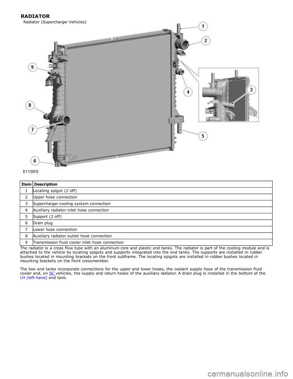
1 Locating spigot (2 off) 2 Upper hose connection 3 Supercharger cooling system connection 4 Auxiliary radiator inlet hose connection 5 Support (2 off) 6 Drain plug 7 Lower hose connection 8 Auxiliary radiator outlet hose connection 9 Transmission fluid cooler inlet hose connection The radiator is a cross flow type with an aluminum core and plastic end tanks. The radiator is part of the cooling module and is
attached to the vehicle by locating spigots and supports integrated into the end tanks. The supports are installed in rubber
bushes located in mounting brackets on the front subframe. The locating spigots are installed in rubber bushes located in
mounting brackets on the front crossmember.
The two end tanks incorporate connections for the upper and lower hoses, the coolant supply hose of the transmission fluid
cooler and, on SC vehicles, the supply and return hoses of the auxiliary radiator. A drain plug is installed in the bottom of the LH (left-hand) end tank. Radiator (Supercharger Vehicles) RADIATOR