2010 JAGUAR XFR high beam
[x] Cancel search: high beamPage 698 of 3039

center and an amber warning indicator will illuminate.
Refer to: Information and Message Center (413-08 Information and Message Center, Description and Operation).
As the wheel speed sensors are active devices, a return signal is available when the road wheels are not rotating. This enables
the ABS module to check the condition of the speed sensors while the vehicle is stationary.
Steering Angle Sensor
The steering angle sensor measures the steering wheel angle and the rate of change of the steering wheel angle. These
measurements are received by the ABS module and broadcast on the high speed CAN bus for use by other systems.
The steering angle sensor is mounted on the steering column upper shroud mounting bracket, immediately behind the
multifunction switches, and is secured by 2 screws. A fly lead connects the sensor to the passenger compartment wiring
harness via a 4 pin multiplug.
The sensor is housed in a 'U' shaped plastic casing and contains two offset LED (light emitting diode)s facing two detectors.
An encoder ring is mounted on the inner steering column shaft and intersects the LEDs and detectors. The encoder ring contains 60 slots which break and restore the light beams between the LEDs and the detectors as the steering wheel is
Page 699 of 3039

beams change state. The LEDs and detectors are mounted in such a way that only one beam will change state, either to broken or restored, at any one time.
The center (straight ahead) position of the steering wheel has to be learned by the ABS module every time the ignition is switched ON. The steering angle sensor is unable to determine the center position so inputs from the yaw rate and lateral
acceleration sensor and wheel speed signals are also used by the ABS module to help it perform this process. If extreme weather conditions are present, for example ice causing extreme wheel spin or understeer/oversteer, the ABS module may not be able to determine the center position of the steering wheel. In this situation 'DSC NOT AVAILABLE' will be displayed in the
instrument cluster message center and the amber warning indicator will illuminate.
Refer to: Information and Message Center (413-08 Information and Message Center, Description and Operation).
'DSC NOT AVAILABLE' will also be displayed if the ABS module detects a steering angle sensor fault. The amber warning indicator will illuminate until the fault is rectified.
Yaw Rate and Lateral Acceleration Sensor
The yaw rate and lateral acceleration sensor is mounted on the rear parcel shelf. The sensor is secured by two screws and
connects to the vehicle wiring via a four pin multiplug.
When the ignition is ON, the sensor receives a power feed from the CJB. The ground path for the sensor is located behind the left hand rear seat back. The sensor measures the yaw rate and lateral acceleration of the vehicle, providing values to the ABS module via a dedicated, private high speed CAN bus connection. The ABS module broadcasts these values on the high speed CAN bus for use by other systems.
If a sensor fault is detected by the ABS module, 'DSC NOT AVAILABLE' will be displayed in the instrument cluster message center and the amber warning indicator will illuminate.
Refer to: Information and Message Center (413-08 Information and Message Center, Description and Operation).
Page 782 of 3039

16 Ball (12 off) 17 Distance keeper 18 Crash tube The column comprises a cast magnesium mounting bracket which provides the attachment to the cross-beam. Attached to the
mounting bracket is a rake lever which is attached to the mounting bracket at the lower end with two pivot bearings. The
bearings allow the rake lever to rotate upwards or downward to adjust the column rake.
The rake lever also provides for the attachment of the rake housing which can slide within the lever to provide the reach
adjustment. Within the rake housing is the axial housing which is supported on each side with 6 ball bearings which allow the
rake housing to move forward or backwards. The bearings on each side are arranged in groups of 3 bearings and are separated
by a distance keeper which allows the housing to supported on bearings along its length. Within the axial housing is a tube
which is supported at the upper end of the column on the upper bearing. The tube has a central splined hole which provides for
the fitment of the splined shaft. The splined shaft can slide within the tube on the splines when the column reach is adjusted
or the column collapses in a crash condition. The splined shaft also passes rotary motion from the steering wheel through the
length of the column to the outer clamping yoke which is supported on the lower bearing.
The electric steering column lock is attached to the top of the rake lever. A lock bolt within the steering column lock engages in
one of 8 slots in the locking sleeve located at the lower end of the column preventing rotation of the steering wheel. The
locking sleeve is retained by a tolerance ring which in turn is located on the outer diameter of the tube yoke. The tolerance
ring allows a specified amount of torque to be applied to the splined shaft before it slips, preventing damage to the column
lock due to excessive force being applied to the steering wheel when the lock is engaged. The tolerance ring is designed to
slip on the splined shaft when the applied torque exceeds the fitted slip load of 200 Nm minimum. Repeated rotation of the
lock collar will reduce its slipping torque to 100 Nm minimum. The lock is controlled by the CJB.
A steering angle sensor is located at the upper end of the steering column and is attached to the crash adaptor. The sensor
measures steering rotation via a toothed wheel located on the splined tube at the upper end of the column. The sensor
receives a power supply from the CJB and supplies 2 signals (A and B) relating to the steering rotation to the ABS (anti-lock brake system) module. The module transmits this data on the high speed CAN bus for use by other vehicle systems. Refer to: Anti-Lock Control - Stability Assist (206-09 Anti-Lock Control - Stability Assist, Description and Operation).
The steering column is adjustable electrically, for reach and rake. The adjustment mechanism comprises an electric adjustment
motor, a lead screw, a rake solenoid, a reach solenoid, a reach clutch and a rake clutch. The column adjustment is controlled
manually using a joystick switch located on the LH (left-hand) side of the column lower cowl. The joystick can be moved
forward and backward to adjust the column reach in and out and moved up and down to adjust the rake. The switch selection
energizes the adjustment motor in the applicable direction and also engages the applicable solenoid and clutch.
When the joystick switch is rotated to the 'auto' position, the steering column will adjust to the uppermost rake position when
the ignition is switched off. It will re-adjust to the position corresponding to the memory position for the remote handset when
the ignition is switched on.
The memory function of the electric column is linked to and controlled by the driver's seat module. The module provides for the
storage of three separate memory positions which are stored against 3 individual remote handsets.
Refer to: Seats (501-10 Seating, Description and Operation).
The steering wheel locates on a splined shaft in the upper column assembly and is secured with a bolt. The steering wheel
houses the driver's airbag and switches for the audio system, gear change and speed control. A clockspring is used to connect
the steering wheel electrical components to the vehicle harness.
Two plastic shrouds are fitted to the upper column assembly. The lower shroud is fitted with an energy absorbing foam pad to
minimize leg injury in the event of an accident.
www.JagDocs.com
Page 797 of 3039

Published: 11-May-2011
Steering Column Switches - Steering Column Switches - Overview
Description and Operation
OVERVIEW
The steering column multifunction switch is situated on the steering column and consists of the wiper switch, the turn signal
indicator/lighting switch and the trip computer switch.
The RH (right-hand) multifunction switch controls the following windshield wiper functions:
Flick wipe
Intermittent wipe
Slow speed wipe
High speed wipe
Wash/Wipe
Headlamp powerwash
Rain sensing / variable wipe selection.
The LH (left-hand) multifunction switch controls the following functions:
Turn signal indicators
Side lamps
Headlamps
Auto lamps
High/low beam
Headlamp flash
Headlamp timer
Trip computer.
The steering column adjustment switch is located in the steering column lower shroud on the LH side. The switch is a 4 position 'joystick' which controls reach and rake adjustment.
The trip button allows the driver to cycle though an option menu and also reset trip cycle mileage calculations. The trip
computer information is displayed in the instrument cluster message centre.
Steering wheel mounted switches on the LH side of the driver's airbag, control the audio and telephone functions. Switches on the RH side of the driver's airbag, control the speed control functions. The steering wheel has an internal heating element. This is controlled by the driver via the Touch Screen Display (TSD). www.JagDocs.com
Page 801 of 3039

battery power supply to be passed via the slip ring assembly in the steering wheel to the heated steering wheel control
module. The steering wheel module supplies power to the steering wheel heater element and also monitors the temperature
via a NTC (negative temperature coefficient) temperature sensor incorporated into the heater element. The control module
varies the power supply to the element to maintain the steering wheel rim at the optimum temperature.
Component Description STEERING COLUMN MULTIFUNCTION SWITCHES
The steering column multifunction switches are situated on the steering column and consists of the wiper switch, the turn
signal indicator/lighting switch and the trip computer switch.
The steering column adjustment switch is located in the steering column lower shroud on the LH side. The switch is a 4 position 'joystick' which controls reach and rake adjustment.
Steering wheel mounted switches on the LH side of the driver's airbag, control the audio and telephone functions. Switches on the RH side of the driver's airbag, control the speed control functions. For additional information, refer to:
Audio System (415-01A Information and Entertainment System, Description and Operation), Speed Control (310-03A, Description and Operation),
Speed Control (310-03B, Description and Operation),
Speed Control (310-03C, Description and Operation).
Two transmission paddle switches are located at the rear of the steering wheel.
Refer to: External Controls (307-05, Description and Operation).
LH Multifunction Switch
Item Description 1 High beam 2 Lighting control rotary switch 3 RH turn signal indicator 4 Headlamp flash 5 LH turn signal indicator 6 Trip computer function button The LH multifunction switch controls the following windshield wiper functions:
Page 802 of 3039

Turn signal indicators
Side lamps
Headlamps
Auto lamps
High/low beam
Headlamp flash
Headlamp timer
Trip computer.
The switch is located in a slot in the clockspring and secured with 2 plastic clips.
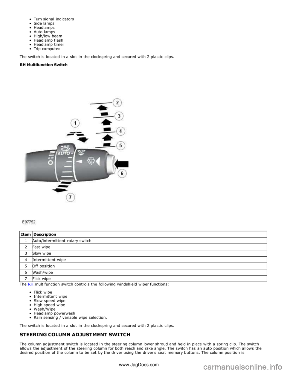
RH Multifunction Switch
The RH multifunction switch controls the following windshield wiper functions: Flick wipe
Intermittent wipe
Slow speed wipe
High speed wipe
Wash/Wipe
Headlamp powerwash
Rain sensing / variable wipe selection.
The switch is located in a slot in the clockspring and secured with 2 plastic clips.
STEERING COLUMN ADJUSTMENT SWITCH
The column adjustment switch is located in the steering column lower shroud and held in place with a spring clip. The switch
allows the adjustment of the steering column for both reach and rake angle. The switch has an auto position which allows the
desired position of the column to be set by the driver using the driver's seat memory buttons. The column position is Item Description 1 Auto/intermittent rotary switch 2 Fast wipe 3 Slow wipe 4 Intermittent wipe 5 Off position 6 Wash/wipe 7 Flick wipe www.JagDocs.com
Page 1641 of 3039

6 Clockspring 7 APP (accelerator pedal position) sensor 8 Electric throttle actuator 9 Brake lamp/brake test switch 10 Adaptive speed control radar sensor 11 Diagnostic socket 12 Instrument cluster 13 TCM (transmission control module) 14 Adaptive speed control module
SPEED CONTROL System Operation
The speed control system uses inputs from the brake lamp/brake test switch, the APP sensor, the ECM and the ABS module.
Speed control is operated by the driver using only the steering wheel switches. When speed control is active, the ECM regulates the PWM (pulse width modulation) signals to the fuel injectors to adjust the fuel supply as required to maintain the
set speed.
During speed control operation, the ECM controls vehicle speed by adjusting fuel injection duration and timing. When the accelerator pedal is pressed with speed control active, the ECM outputs a calculated throttle angle signal in place of the actual throttle angle signals produced by the APP sensor. The calculated throttle angle is derived from fuel demand.
The minimum set speed for speed control is 18 mph (30 (km/h). Speed control is automatically suspended if the following
conditions apply:
Vehicle speed falls below 18 mph (30 km/h)
The brake pedal is pressed
The cancel button is pressed
Neutral, park or reverse gear is selected
The difference between actual speed and the set speed is too great
If the engine speed becomes near to the red line (maximum engine speed)
If the accelerator pedal is used to accelerate beyond the set speed for too long.
ADAPTIVE SPEED CONTROL
The adaptive speed control system comprises the following components:
Adaptive speed control sensor
Adaptive speed control module
Steering wheel control switches
ECM
Electric throttle actuator
ABS module and pump Adaptive speed control warning indicator.
The adaptive speed control system uses a forward looking radar sensor to scan the road ahead, looking for objects that are
moving at a different rate to itself. When a target is identified the adaptive speed control system will monitor the time gap
between it and the target vehicle. When that gap falls below a set driver selected level the adaptive speed control system will
intervene slowing the vehicle by backing off the throttle and/ or applying the brakes, until the correct gap is attained. The
driver can chose between four gap settings, 1, 1.4, 1.8 and 2.2 seconds.
The system will detect but not react to the following:
Vehicles in the oncoming lane
Stationary vehicles
Pedestrians
Vehicles not in the same lane.
Adaptive speed control is active when the vehicle is moving. Adaptive Speed Control only functions when a set speed is
entered in normal speed control mode. The adaptive speed control system only intervenes with the set speed when it detects
a target vehicle, and then only if the minimum time gap is breached.
It is important to note that the system is intended for use in limited driving situations, does not remove control and
responsibility from the driver, and at all times can be quickly overridden. The adaptive speed control system is not a collision
warning system and will not react to stationary objects. The system does not operate below a minimum speed of
approximately 30 km/h (20 mph) since it is unsuitable for use in cities or congested traffic. The system is best suited to main
roads/ highways with gradual bends.
The ECM, throttle body and throttle control are unchanged from those used for non adaptive speed control variants.
The adaptive speed control system is based on the use of a front mounted radar sensor. The sensor transmits a 1.5° wide
beam forward of the vehicle and detects the returning signals reflected off other vehicles and objects ahead.
The 1.5° wide radar beam is mechanically scanned at a rate of 10 sweeps/second across a total arc of 15° centered on the
Page 1642 of 3039

longitudinal axis of the vehicle. The radar operates at millimetric wavelengths (76 - 77 GHz) and transmits a frequency
modulated continuous wave signal at a relatively low power level (no high power pulses).
With the ignition ON, the adaptive speed control module is powered up but no radar transmissions are emitted until the
vehicle is in motion.
In follow mode a set speed is selected in the normal speed control manner and this speed is maintained until a slower vehicle
is encountered in the lane ahead. When the vehicle ahead comes within the effective range of the radar sensor, the system
identifies it as a target vehicle and an icon is illuminated on the instrument cluster to indicate that the system is in "follow
mode". When the distance between the two vehicles closes to a set time gap, the adaptive speed control system closes the
throttle and if necessary applies the brakes to maintain the set time gap. Follow mode is effectively a closed loop system. If
several vehicles are ahead, the closest vehicle is chosen as the target to follow. If the target vehicle moves out of radar range,
or if either vehicle changes lane or drops below the minimum operating speed, the system exits follow mode and the follow
mode icon is extinguished. The adaptive speed control system will only raise its speed to the originally set speed, it will not
accelerate past this speed to maintain a time gap.
Driver operation of the foot brake or control switches will immediately cancel adaptive speed control.
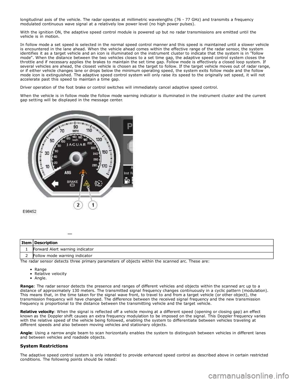
When the vehicle is in follow mode the follow mode warning indicator is illuminated in the instrument cluster and the current
gap setting will be displayed in the message center.
The radar sensor detects three primary parameters of objects within the scanned arc. These are:
Range
Relative velocity
Angle.
Range: The radar sensor detects the presence and ranges of different vehicles and objects within the scanned arc up to a
distance of approximately 130 meters. The transmitted signal frequency changes continuously in a cyclic pattern (modulation).
This means that, in the time taken for the signal wave front, to travel to and from a target vehicle (or other object), the
transmission frequency will have changed. The difference between the received signal frequency and the new transmission
frequency is proportional to the distance between the transmitting vehicle and the target vehicle.
Relative velocity: When the signal is reflected off a vehicle moving at a different speed (opening or closing gap) an effect
known as the Doppler shift causes an extra frequency modulation to be imposed on the signal. This Doppler frequency varies
with the relative speed of the vehicle being followed, enabling the system to differentiate between vehicles traveling at
different speeds and also between moving vehicles and stationary objects.
Angle: Using a narrow angle beam to scan horizontally enables the system to distinguish between vehicles in different lanes
and between vehicles and roadside objects.
System Restrictions
The adaptive speed control system is only intended to provide enhanced speed control as described above in certain restricted
conditions. The following points should be noted: Item Description 1 Forward Alert warning indicator 2 Follow mode warning indicator