2010 JAGUAR XFR catalytic converter
[x] Cancel search: catalytic converterPage 16 of 3039

307-02B: Transmission/Transaxle Cooling - TDV6 3.0L Diesel /V8 5.0L Petrol/V8 S/C 5.0L
PetrolSpecificationDescription and OperationComponent Location
Overview
System Operation and Component DescriptionDiagnosis and TestingTransmission CoolingRemoval and InstallationTransmission Fluid Cooler - V8 5.0L Petrol/V8 S/C 5.0L Petrol
Transmission Fluid Cooler Tubes - V8 5.0L Petrol/V8 S/C 5.0L Petrol307-05B: Automatic Transmission/Transaxle External Controls - TDV6 3.0L Diesel /V8 5.0L
Petrol/V8 S/C 5.0L PetrolSpecificationDescription and OperationComponent Location
Overview
System Operation and Component DescriptionDiagnosis and TestingExternal ControlsRemoval and InstallationTransmission Control Switch (TCS)
Transmission Control Switch (TCS) Knob
Emergency Park Position Release Lever
Upshift
Paddle Switch
Downshift Paddle Switch309: Exhaust System
309-00C: Exhaust System - V8 5.0L Petrol/V8 S/C 5.0L PetrolSpecificationDescription and OperationComponent Location
Overview
System Operation and Component DescriptionDiagnosis and TestingExhaust SystemRemoval and InstallationCatalytic Converter LH
Catalytic Converter RH
Exhaust Sound Enhancement Valve
Exhaust System
Front Muffler
Rear Muffler
Page 53 of 3039

Bus Topology of a
communication
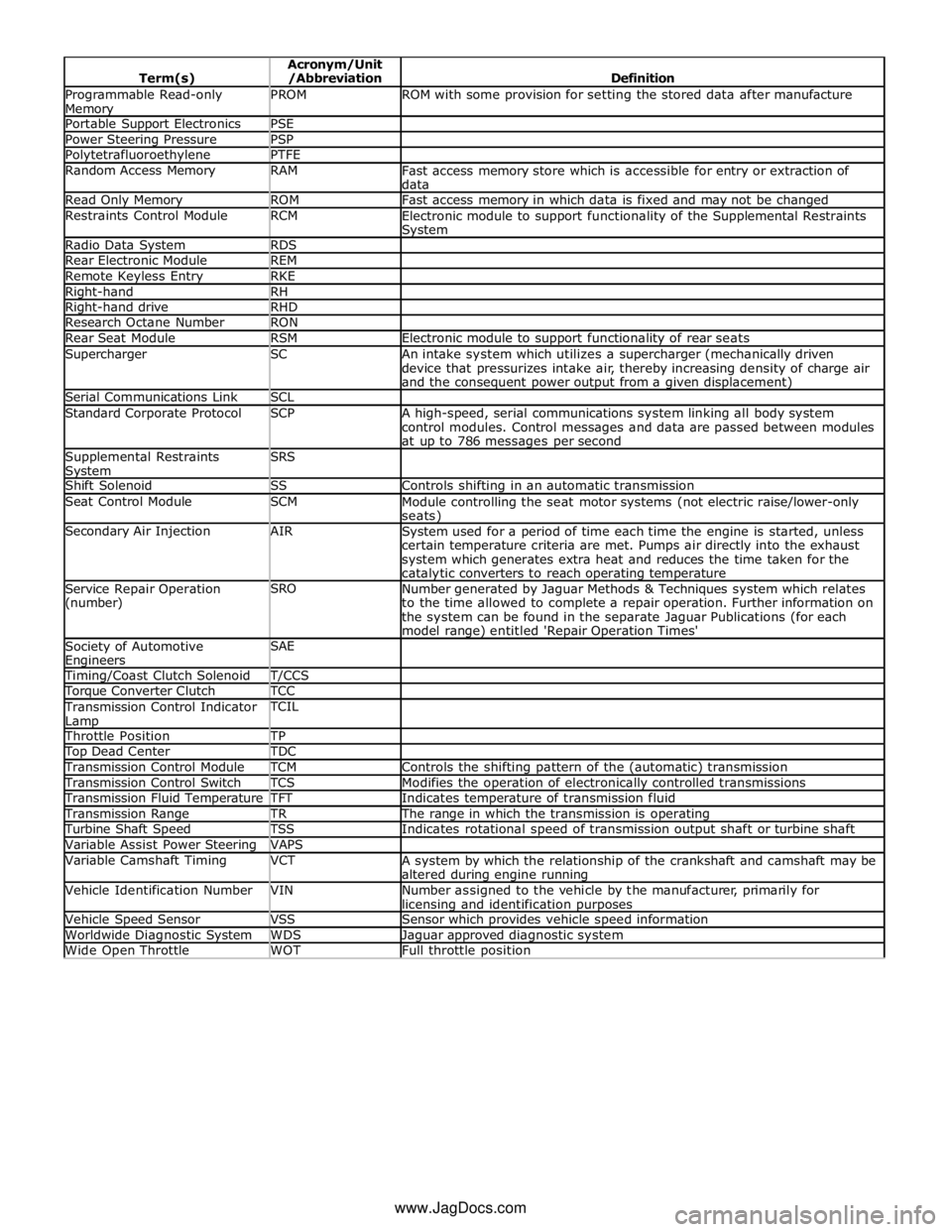
network Coast Clutch Solenoid CCS Camshaft Position CMP Indicates camshaft position Carbon dioxide CO² Colorless gas with a density of approximately 1.5 times that of air Carbon monoxide CO Poisonous gas produced as the result of incomplete combustion Chlorofluorocarbon CFC Catalytic converter
In-line exhaust system device used to reduce the level of engine exhaust
emissions Celsius C
SI term for the Centigrade scale, with freezing point at zero and boiling point at 100 degrees Compact Disc CD Cylinder Head Temperature
Sensor CHT Sensor A sensor for measuring the temperature of the cylinder head Central Junction Box CJB Crankshaft Position CKP Indicates crankshaft position Clutch Pedal Position CPP Indicates clutch pedal position Controller Area Network CAN
A communication system which allows control modules to be linked together Constant Velocity CV Cubic centimeter cm³ Central Security Module CSM Electronic module to support security system functionality Data Link Connector DLC
Connector providing access and/or control of the vehicle information, operating conditions, and diagnostic information Driver Door Module DDM Electronic module to support driver door functionality Driver Seat Module DSM Electronic module to support driver seat functionality Daytime Running Lamps DRL Deutsche Institut fur Normung DIN German standards regulation body Diagnostic Trouble Code DTC
An alpha/numeric identifier for a fault condition identified by the On-Board Diagnostic (OBD) system Direct current dc
Current which flows in one direction only, though it may have appreciable pulsations in its magnitude Domestic Data Bus D2B Digital Versatile Disc DVD Electronic Automatic Temperature Control EATC
Exhaust Gas Recirculation EGR Exhaust Gas Recirculation Temperature Sensor EGRT Sensing EGR function based on temperature change Electronic Brake Force
Distribution EBD
Engine Control Module ECM Electronic module to support engine functionality Electronic Crash Sensor ECS Sensor to measure severity of impact Engine Coolant Temperature ECT Engine Oil Pressure EOP European On-Board Diagnostic EOBD Electronic Pressure Control EPC Electrically Erasable
Programmable Read-Only Memory EEPROM
Erasable Programmable
Read-Only Memory EPROM
Evaporative Emission EVAP
System designed to prevent fuel vapor from escaping into the atmosphere. Typically includes a charcoal filled canister to absorb fuel vapor Flash Electrically Erasable
Programmable Read-Only Memory FEEPROM
Front Electronic Module FEM Flash Erasable Programmable
Read-Only Memory FEPROM
Frequency Modulation FM Fuel Pump Driver Module FPDM Fuel Rail Pressure FRP Generic Electronic Module GEM Ground GND
Electrical conductor used as a common return for an electrical circuit or
circuits, and with a relative zero potential Global Positioning System GPS Global System for Mobile
Communication GSM
Gross Vehicle Weight GVW Heated Oxygen Sensor HO2S Electrically heated oxygen sensor which induces fuelling corrections
Page 55 of 3039

Programmable Read-only Memory PROM ROM with some provision for setting the stored data after manufacture Portable Support Electronics PSE Power Steering Pressure PSP Polytetrafluoroethylene PTFE Random Access Memory RAM
Fast access memory store which is accessible for entry or extraction of
data Read Only Memory ROM Fast access memory in which data is fixed and may not be changed Restraints Control Module RCM
Electronic module to support functionality of the Supplemental Restraints System Radio Data System RDS Rear Electronic Module REM Remote Keyless Entry RKE Right-hand RH Right-hand drive RHD Research Octane Number RON Rear Seat Module RSM Electronic module to support functionality of rear seats Supercharger SC
An intake system which utilizes a supercharger (mechanically driven
device that pressurizes intake air, thereby increasing density of charge air
and the consequent power output from a given displacement) Serial Communications Link SCL Standard Corporate Protocol SCP
A high-speed, serial communications system linking all body system
control modules. Control messages and data are passed between modules
at up to 786 messages per second Supplemental Restraints System SRS
Shift Solenoid SS Controls shifting in an automatic transmission Seat Control Module SCM
Module controlling the seat motor systems (not electric raise/lower-only seats) Secondary Air Injection AIR
System used for a period of time each time the engine is started, unless
certain temperature criteria are met. Pumps air directly into the exhaust
system which generates extra heat and reduces the time taken for the catalytic converters to reach operating temperature Service Repair Operation
(number) SRO
Number generated by Jaguar Methods & Techniques system which relates
to the time allowed to complete a repair operation. Further information on
the system can be found in the separate Jaguar Publications (for each
model range) entitled 'Repair Operation Times' Society of Automotive Engineers SAE
Timing/Coast Clutch Solenoid T/CCS Torque Converter Clutch TCC Transmission Control Indicator
Lamp TCIL
Throttle Position TP Top Dead Center TDC Transmission Control Module TCM Controls the shifting pattern of the (automatic) transmission Transmission Control Switch TCS Modifies the operation of electronically controlled transmissions Transmission Fluid Temperature TFT Indicates temperature of transmission fluid Transmission Range TR The range in which the transmission is operating Turbine Shaft Speed TSS Indicates rotational speed of transmission output shaft or turbine shaft Variable Assist Power Steering VAPS Variable Camshaft Timing VCT
A system by which the relationship of the crankshaft and camshaft may be
altered during engine running Vehicle Identification Number VIN
Number assigned to the vehicle by the manufacturer, primarily for licensing and identification purposes Vehicle Speed Sensor VSS Sensor which provides vehicle speed information Worldwide Diagnostic System WDS Jaguar approved diagnostic system Wide Open Throttle WOT Full throttle position www.JagDocs.com
Page 305 of 3039

Noise, Vibration and Harshness - Exhaust System Neutralizing
General Procedures Published: 11-May-2011
1. Loosen the muffler inlet pipe and resonator pipe to exhaust manifold
fasteners at the flanges and the muffler inlet connection.
2. Place a stand to support the muffler parallel to the vehicle frame with
the muffler pipe bracket free of stress.
3. Tighten the muffler connection.
4. Position the exhaust pipes to the manifolds and tighten. Make sure that
the catalytic converter and heat shield do not contact the frame rails.
5. With the complete exhaust system tight (and cooled) the rear hanger
insulator should be angled forward, to allow the system to expand
rearward when heated during normal running
Page 505 of 3039

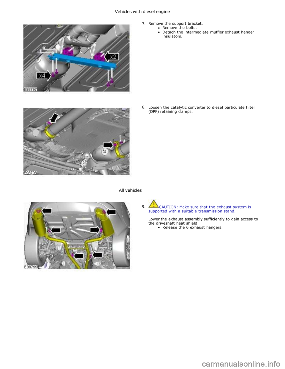
Vehicles with diesel engine
7.
8.
All vehicles
9.
Remove the support bracket.
Remove the bolts.
Detach the intermediate muffler exhaust hanger
insulators.
Loosen the catalytic converter to diesel particulate filter
(DPF) retaining clamps.
CAUTION: Make sure that the exhaust system is
supported with a suitable transmission stand.
Lower the exhaust assembly sufficiently to gain access to
the driveshaft heat shield.
Release the 6 exhaust hangers.
Page 508 of 3039

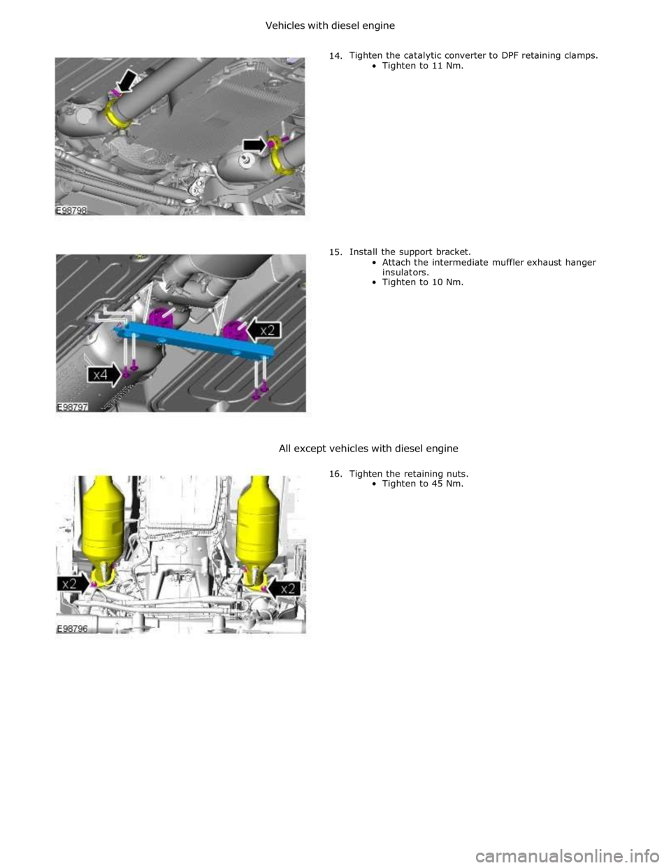
Vehicles with diesel engine
14.
15. Tighten the catalytic converter to DPF retaining clamps.
Tighten to 11 Nm.
Install the support bracket.
Attach the intermediate muffler exhaust hanger
insulators.
Tighten to 10 Nm.
All except vehicles with diesel engine
16. Tighten the retaining nuts.
Tighten to 45 Nm.
Page 812 of 3039

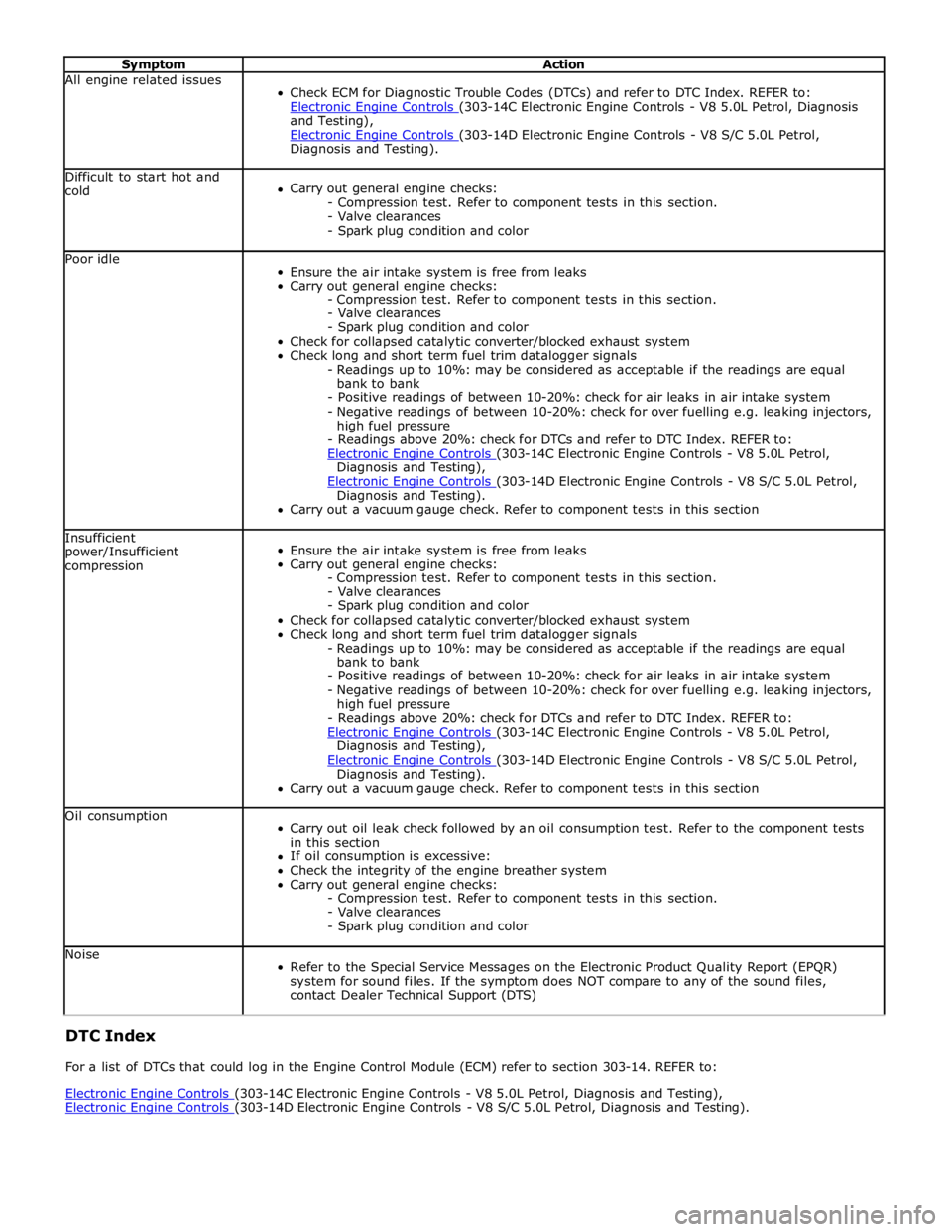
Symptom Action All engine related issues
Check ECM for Diagnostic Trouble Codes (DTCs) and refer to DTC Index. REFER to:
Electronic Engine Controls (303-14C Electronic Engine Controls - V8 5.0L Petrol, Diagnosis and Testing),
Electronic Engine Controls (303-14D Electronic Engine Controls - V8 S/C 5.0L Petrol, Diagnosis and Testing). Difficult to start hot and
cold
Carry out general engine checks:
- Compression test. Refer to component tests in this section.
- Valve clearances
- Spark plug condition and color Poor idle
Ensure the air intake system is free from leaks
Carry out general engine checks:
- Compression test. Refer to component tests in this section.
- Valve clearances
- Spark plug condition and color
Check for collapsed catalytic converter/blocked exhaust system
Check long and short term fuel trim datalogger signals
- Readings up to 10%: may be considered as acceptable if the readings are equal
bank to bank
- Positive readings of between 10-20%: check for air leaks in air intake system
- Negative readings of between 10-20%: check for over fuelling e.g. leaking injectors,
high fuel pressure
- Readings above 20%: check for DTCs and refer to DTC Index. REFER to:
Electronic Engine Controls (303-14C Electronic Engine Controls - V8 5.0L Petrol, Diagnosis and Testing),
Electronic Engine Controls (303-14D Electronic Engine Controls - V8 S/C 5.0L Petrol, Diagnosis and Testing).
Carry out a vacuum gauge check. Refer to component tests in this section Insufficient
power/Insufficient
compression
Ensure the air intake system is free from leaks
Carry out general engine checks:
- Compression test. Refer to component tests in this section.
- Valve clearances
- Spark plug condition and color
Check for collapsed catalytic converter/blocked exhaust system
Check long and short term fuel trim datalogger signals
- Readings up to 10%: may be considered as acceptable if the readings are equal
bank to bank
- Positive readings of between 10-20%: check for air leaks in air intake system
- Negative readings of between 10-20%: check for over fuelling e.g. leaking injectors,
high fuel pressure
- Readings above 20%: check for DTCs and refer to DTC Index. REFER to:
Electronic Engine Controls (303-14C Electronic Engine Controls - V8 5.0L Petrol, Diagnosis and Testing),
Electronic Engine Controls (303-14D Electronic Engine Controls - V8 S/C 5.0L Petrol, Diagnosis and Testing).
Carry out a vacuum gauge check. Refer to component tests in this section Oil consumption
Carry out oil leak check followed by an oil consumption test. Refer to the component tests
in this section
If oil consumption is excessive:
Check the integrity of the engine breather system
Carry out general engine checks:
- Compression test. Refer to component tests in this section.
- Valve clearances
- Spark plug condition and color Noise
Refer to the Special Service Messages on the Electronic Product Quality Report (EPQR)
system for sound files. If the symptom does NOT compare to any of the sound files,
contact Dealer Technical Support (DTS) DTC Index
For a list of DTCs that could log in the Engine Control Module (ECM) refer to section 303-14. REFER to:
Electronic Engine Controls (303-14C Electronic Engine Controls - V8 5.0L Petrol, Diagnosis and Testing), Electronic Engine Controls (303-14D Electronic Engine Controls - V8 S/C 5.0L Petrol, Diagnosis and Testing).
Page 969 of 3039

Engine - V8 S/C 5.0L Petrol - Exhaust Manifold LH
Removal and Installation
Special Tool(s)
303-1444-01
Exhaust Manifold Installation Guide Pins - Threaded
303-1444-02
Exhaust Manifold Installation Guide Pins - Unthreaded Removal
NOTES:
Removal steps in this procedure may contain installation details.
Some variation in the illustrations may occur, but the essential information is always correct. Published: 11-May-2011
1. Refer to: Battery Disconnect and Connect (414-01 Battery, Mounting and Cables, General Procedures).
2. WARNING: Do not work on or under a vehicle supported only by a jack.
Always support the vehicle on safety stands.
Raise and support the vehicle.
3. Refer to: Power Steering Pump - V8 5.0L Petrol/V8 S/C 5.0L Petrol (211-02 Power Steering, Removal and Installation).
4. Refer to: Catalytic Converter LH (309-00C Exhaust System - V8 5.0L Petrol/V8 S/C 5.0L Petrol, Removal and Installation).