2010 JAGUAR XFR sat nav
[x] Cancel search: sat navPage 22 of 3039

Operation and
Component DescriptionCellular PhoneComponent
Location
Overview
System Operation
and Component DescriptionNavigation SystemComponent Location
Overview
System Operation and Component DescriptionVideo SystemComponent
Location
Overview
System Operation
and Component DescriptionDiagnosis and TestingInformation and Entertainment SystemRemoval and InstallationAudio Unit
Audio Unit Antenna Amplifier
Audio and Climate Control Assembly
Front Door Speaker
Information and Entertainment Display
Information and Entertainment Module
Instrument Panel Speaker
Rear Door Speaker
Steering Wheel Audio Controls
Subwoofer Amplifier
Subwoofer Speaker
Satellite Radio Tuner415-01B: Information and Entertainment System - DTC: Audio Input Control Module
Diagnosis and TestingAudio Input Control Module417: Lighting
417-01: Exterior LightingSpecificationDescription and OperationComponent Location
Overview
System Operation and Component DescriptionDiagnosis and TestingHeadlampsGeneral ProceduresHeadlamp Adjustment (86.40.18)
Page 816 of 3039
9. WEAK VALVE SPRINGS: When the needle oscillation becomes more violent as engine RPM is increased, weak valve
springs are indicated. The reading at idle could be relatively steady.
10. LATE VALVE TIMING: A steady but low reading could be caused by late valve timing.
11.
IGNITION TIMING RETARDED: Retarded ignition timing will produce a steady but somewhat low reading.
12.
INSUFFICIENT SPARK PLUG GAP: When spark plugs are gapped too close, a regular, small pulsation of the needle can
occur.
13. INTAKE LEAK: A low, steady reading can be caused by an intake manifold or throttle body gasket leak.
14.
BLOWN HEAD GASKET: A regular drop of fair magnitude can be caused by a blown head gasket or warped cylinder head
to cylinder block surface.
15.
RESTRICTED EXHAUST SYSTEM: When the engine is first started and is idled, the reading may be normal, but as the
engine RPM is increased, the back pressure caused by a clogged muffler, kinked tail pipe or other concerns will cause
the needle to slowly drop to 0 kPa (0 in-Hg). The needle then may slowly rise. Excessive exhaust clogging will cause
the needle to drop to a low point even if the engine is only idling.
When vacuum leaks are indicated, search out and correct the cause. Excess air leaking into the system will upset the fuel
mixture and cause concerns such as rough idle, missing on acceleration or burned valves. If the leak exists in an accessory
such as the power brake booster, the unit will not function correctly. Always repair vacuum leaks.
Engine Oil Pressure Check
NOTE: Prior to checking the engine oil pressure, a road test of 6 miles (10 kilometres), must be carried out. Do not
attempt to attain engine normal operating temperature by allowing the engine to idle.
1. Disconnect the battery ground cable. Refer to section 414-00 - Charging System - General Information of the workshop
manual
2. WARNINGS:
The spilling of hot engine oil is unavoidable during this procedure, care must be taken to prevent scalding.
Wear protective gloves.
Remove the engine oil filter element
REFER to: Oil Filter Element (303-01C Engine - V8 5.0L Petrol, Removal and Installation).
NOTE: Ensure the oil filter element is not contaminated during this procedure
3. Install the oil filter element into special tool (Oil filter adapter number 303-1451)
4. Install the special tool (Oil filter adapter number 303-1451) to the engine. Torque: 25 Nm
5. Install the special tool (Oil pressure testing gauge, 303-871) and tighten the union
6. Connect the battery ground cable
7. Refer to owner hand book, check and top-up the engine oil if required
8. Start and run the engine
9. Note the oil pressure readings with the engine running at idle and 3500 RPM
10.
Turn off the engine
11.
Disconnect the battery ground cable
12. Remove the special tools
1. Clean the components
13.
Install the engine oil filter element
REFER to: Oil Filter Element (303-01C Engine - V8 5.0L Petrol, Removal and Installation).
NOTE: Ensure the oil filter element is not contaminated during this procedure
14.
Connect the battery ground cable
15. Refer to owner hand book, check and top-up the engine oil if required
www.JagDocs.com
Page 1820 of 3039

Published: 11-May-2011
Information and Message Center - Information and Message Center - Overview
Description and Operation
OVERVIEW
The message center is a LCD (liquid crystal display) located in a central position in the instrument cluster. The message center
receives CAN (controller area network) bus, LIN (local interconnect network) bus, and hardwired signals from other vehicle
system control modules to display current vehicle status information. Depending on message importance, the message center
will be backlit in white, amber or red.
The message center will display:
Fuel level
Trip computer information
Gear selected
Speed control information
Vehicle map
Clock
Turn by turn satellite navigation
Voice control text
JaguarDrive Control system messages.
Operation of the message center is controlled by software within the instrument cluster.
Refer to: Instrument Cluster (413-01 Instrument Cluster, Description and Operation).
Page 1930 of 3039
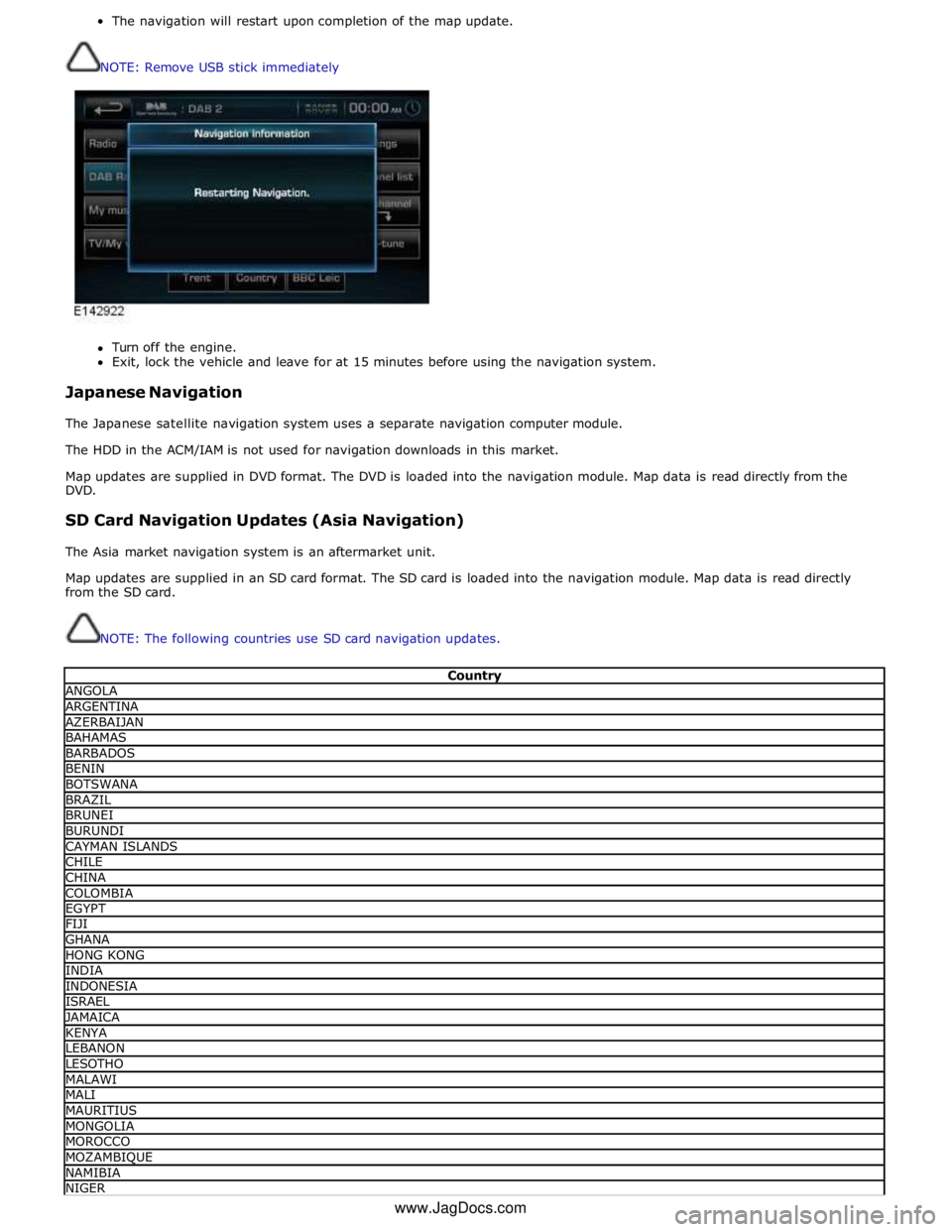
The navigation will restart upon completion of the map update.
NOTE: Remove USB stick immediately
Turn off the engine.
Exit, lock the vehicle and leave for at 15 minutes before using the navigation system.
Japanese Navigation
The Japanese satellite navigation system uses a separate navigation computer module.
The HDD in the ACM/IAM is not used for navigation downloads in this market.
Map updates are supplied in DVD format. The DVD is loaded into the navigation module. Map data is read directly from the
DVD.
SD Card Navigation Updates (Asia Navigation)
The Asia market navigation system is an aftermarket unit.
Map updates are supplied in an SD card format. The SD card is loaded into the navigation module. Map data is read directly
from the SD card.
NOTE: The following countries use SD card navigation updates.
Country ANGOLA ARGENTINA AZERBAIJAN BAHAMAS BARBADOS BENIN BOTSWANA BRAZIL BRUNEI BURUNDI CAYMAN ISLANDS CHILE CHINA COLOMBIA EGYPT FIJI GHANA HONG KONG INDIA INDONESIA ISRAEL JAMAICA KENYA LEBANON LESOTHO MALAWI MALI MAURITIUS MONGOLIA MOROCCO MOZAMBIQUE NAMIBIA NIGER www.JagDocs.com
Page 1932 of 3039
Published: 11-Jul-2014
Information and Entertainment System - General Information - Information
and Entertainment System
Diagnosis and Testing
Principle of Operation
For a detailed description of the Information and Entertainment System, refer to the relevant Description and Operation
sections in the workshop manual. REFER to: (415-01A Information and Entertainment System)
Audio System (Description and Operation), Audio System (Description and Operation), Audio System (Description and Operation).
Inspection and Verification
CAUTION: Diagnosis by substitution from a donor vehicle is NOT acceptable. Substitution of control modules does not
guarantee confirmation of a fault, and may also cause additional faults in the vehicle being tested and/or the donor vehicle.
1. Verify the customer concern.
2. Visually inspect for obvious signs of damage and system integrity.
Visual Inspection
Mechanical Electrical
Information and entertainment module
Audio amplifier module
Integrated audio module
Portable audio interface module
Digital audio broadcast module
Integrated control panel
Touch screen display
Satellite radio module
Television module
Navigation system module
Telephone module
Compact disc player jammed, not loading
Scratched/dirty compact discs
Speakers
Fuses
Loose or corroded connector(s)
Information and entertainment module
Audio amplifier module
Integrated audio module
Portable audio interface module
Digital audio broadcast module
Integrated control panel
Touch screen display
Satellite radio module
Television module
Navigation system module
Telephone module
Speakers
3. If an obvious cause for an observed or reported concern is found, correct the cause (if possible) before proceeding to
the next step.
4. If the cause is not visually evident, check for Diagnostic Trouble Codes (DTCs) and refer to the relevant DTC Index.
Symptom Chart
Symptom Display Possible Causes Action Poor audio quality (all
sources) Display normal
MOST harness
connections loose
MOST harness
connections
contaminated
MOST harness
misrouted
- Too many
bends
- Bend radius
less than
25mm
Check MOST harness connectors for
security
Check MOST harness connectors for
contamination
Check the routing of the MOST harness Information and
entertainment system
inoperative Touch screen blank or
displaying a flashing
logo
MOST network fault
REFER to: Communications Network (418-00 Module Communications Network,
Diagnosis and Testing).
DTC Index
For a list of Diagnostic Trouble Codes (DTCs) that could be logged on this vehicle, please refer to Section 100-00. REFER to:
(100-00 General Information)
Page 1939 of 3039
Published: 11-May-2011
Information and Entertainment System - General Information - Navigation
System
Diagnosis and Testing
Principle of Operation
For a detailed description of the Navigation System, refer to the relevant Description and Operation sections in the workshop
manual. REFER to: (415-01 Information and Entertainment System)
Navigation System (Description and Operation),
Navigation System (Description and Operation),
Navigation System (Description and Operation),
Video System (Description and Operation),
Video System (Description and Operation),
Video System (Description and Operation).
Inspection and Verification
CAUTION: Diagnosis by substitution from a donor vehicle is NOT acceptable. Substitution of control modules does not
guarantee confirmation of a fault, and may also cause additional faults in the vehicle being tested and/or the donor vehicle.
1. Verify the customer concern.
2. Visually inspect for obvious signs of damage and system integrity.
Visual Inspection
Mechanical Electrical
Information and entertainment module
Audio amplifier module
Integrated audio module
Portable audio interface module
Digital audio broadcast module
Integrated control panel
Touch screen display
Satellite radio module
Television module
Navigation system module
Telephone module
Compact disc player jammed, not loading
Scratched/dirty compact discs
Speakers
Fuses
Loose or corroded connector(s)
Information and entertainment module
Audio amplifier module
Integrated audio module
Portable audio interface module
Digital audio broadcast module
Integrated control panel
Touch screen display
Satellite radio module
Television module
Navigation system module
Telephone module
Speakers
3. If an obvious cause for an observed or reported concern is found, correct the cause (if possible) before proceeding to
the next step.
4. If the cause is not visually evident, check for Diagnostic Trouble Codes (DTCs) and refer to the relevant DTC Index.
DTC Index
Navigation System Module
CAUTION: When probing connectors to take measurements in the course of the pinpoint tests, use the adaptor kit, part
number 3548-1358-00
NOTES:
If the control module or a component is suspect and the vehicle remains under manufacturer warranty, refer to the
Warranty Policy and Procedures manual (section B1.2), or determine if any prior approval programme is in operation, prior to
the installation of a new module/component.
Generic scan tools may not read the codes listed, or may read only five digit codes. Match the five digits from the scan
tool to the first five digits of the seven digit code listed to identify the fault (the last two digits give extra information read by
the manufacturer-approved diagnostic system).
When performing voltage or resistance tests, always use a digital multimeter (DMM) accurate to three decimal places and
with a current calibration certificate. When testing resistance, always take the resistance of the DMM leads into account.
Page 1940 of 3039
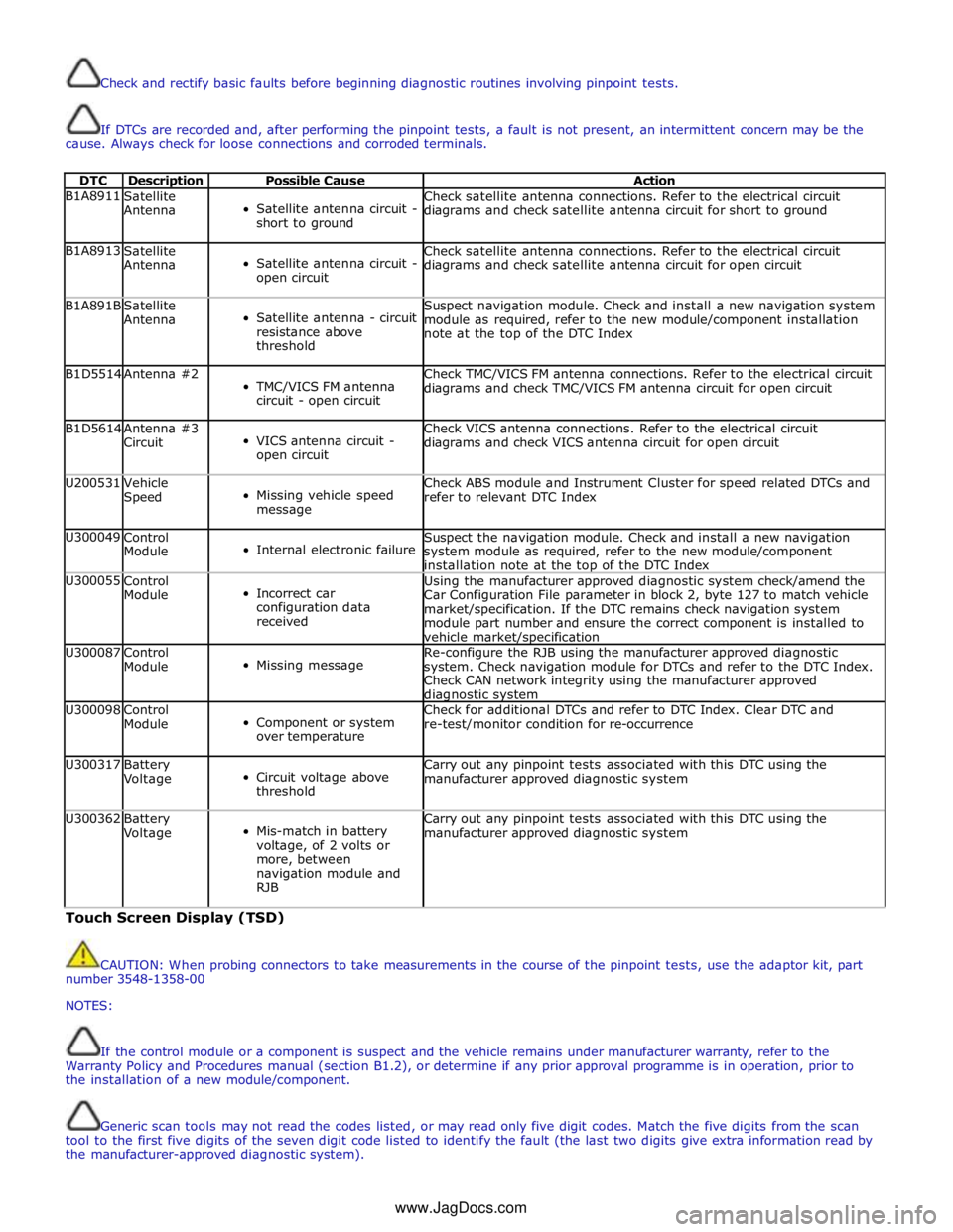
Check and rectify basic faults before beginning diagnostic routines involving pinpoint tests.
If DTCs are recorded and, after performing the pinpoint tests, a fault is not present, an intermittent concern may be the
cause. Always check for loose connections and corroded terminals.
DTC Description Possible Cause Action B1A8911
Satellite
Antenna
Satellite antenna circuit -
short to ground Check satellite antenna connections. Refer to the electrical circuit
diagrams and check satellite antenna circuit for short to ground B1A8913
Satellite
Antenna
Satellite antenna circuit -
open circuit Check satellite antenna connections. Refer to the electrical circuit
diagrams and check satellite antenna circuit for open circuit B1A891B
Satellite
Antenna
Satellite antenna - circuit
resistance above
threshold Suspect navigation module. Check and install a new navigation system
module as required, refer to the new module/component installation
note at the top of the DTC Index B1D5514 Antenna #2
TMC/VICS FM antenna
circuit - open circuit Check TMC/VICS FM antenna connections. Refer to the electrical circuit
diagrams and check TMC/VICS FM antenna circuit for open circuit B1D5614
Antenna #3
Circuit
VICS antenna circuit -
open circuit Check VICS antenna connections. Refer to the electrical circuit
diagrams and check VICS antenna circuit for open circuit U200531
Vehicle
Speed
Missing vehicle speed
message Check ABS module and Instrument Cluster for speed related DTCs and
refer to relevant DTC Index U300049
Control
Module
Internal electronic failure Suspect the navigation module. Check and install a new navigation
system module as required, refer to the new module/component
installation note at the top of the DTC Index U300055
Control
Module
Incorrect car
configuration data
received Using the manufacturer approved diagnostic system check/amend the
Car Configuration File parameter in block 2, byte 127 to match vehicle
market/specification. If the DTC remains check navigation system
module part number and ensure the correct component is installed to
vehicle market/specification U300087
Control
Module
Missing message Re-configure the RJB using the manufacturer approved diagnostic
system. Check navigation module for DTCs and refer to the DTC Index.
Check CAN network integrity using the manufacturer approved diagnostic system U300098
Control
Module
Component or system
over temperature Check for additional DTCs and refer to DTC Index. Clear DTC and
re-test/monitor condition for re-occurrence U300317
Battery
Voltage
Circuit voltage above
threshold Carry out any pinpoint tests associated with this DTC using the
manufacturer approved diagnostic system U300362
Battery
Voltage
Mis-match in battery
voltage, of 2 volts or
more, between
navigation module and
RJB Carry out any pinpoint tests associated with this DTC using the
manufacturer approved diagnostic system Touch Screen Display (TSD)
CAUTION: When probing connectors to take measurements in the course of the pinpoint tests, use the adaptor kit, part
number 3548-1358-00
NOTES:
If the control module or a component is suspect and the vehicle remains under manufacturer warranty, refer to the
Warranty Policy and Procedures manual (section B1.2), or determine if any prior approval programme is in operation, prior to
the installation of a new module/component.
Generic scan tools may not read the codes listed, or may read only five digit codes. Match the five digits from the scan
tool to the first five digits of the seven digit code listed to identify the fault (the last two digits give extra information read by
the manufacturer-approved diagnostic system).
www.JagDocs.com
Page 1947 of 3039
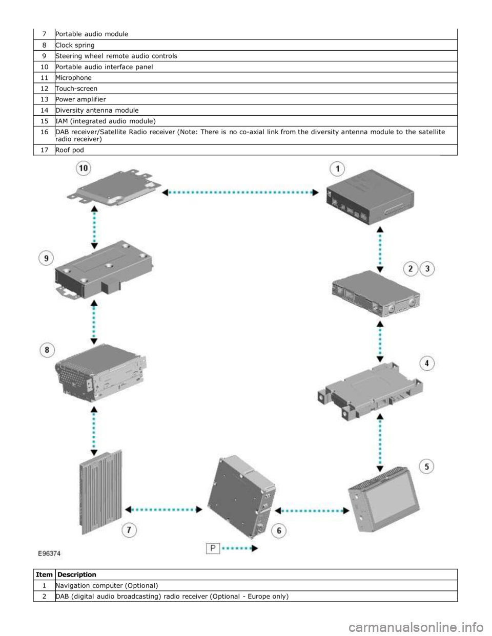
8 Clock spring 9 Steering wheel remote audio controls 10 Portable audio interface panel 11 Microphone 12 Touch-screen 13 Power amplifier 14 Diversity antenna module 15 IAM (integrated audio module) 16 DAB receiver/Satellite Radio receiver (Note: There is no co-axial link from the diversity antenna module to the satellite radio receiver) 17 Roof pod
Item Description 1 Navigation computer (Optional) 2 DAB (digital audio broadcasting) radio receiver (Optional - Europe only)