2010 JAGUAR XFR child lock
[x] Cancel search: child lockPage 2415 of 3039
7 Window regulator motor – driver's door 8 Door module – LH (left-hand) rear passenger 9 Window control switch - LH rear passenger 10 Window regulator motor – LH rear passenger 11 Door module – front passenger 12 Window control switches - front passenger 13 Window regulator motor – front passenger 14 Door module – RH (right-hand) rear passenger 15 Window control switch - RH rear passenger 16 Window regulator motor – RH rear passenger
Door Windows System Operation
All windows can be operated individually, or by the driver’s window control switch. The operation of the windows is proportional
to the switch activation. All windows can be controlled by ‘one touch’ in an upward or downward direction. When the ‘one
touch’ operation is activated in the upwards direction ‘pinch protection‘ is enabled. If a pinch condition is detected the window
will automatically stop and travel downwards to a pre-determined position.
When the rear window ‘one touch’ operation is activated in the downward direction, the window will drop a limited way down.
This is the comfort setting to achieve optimum noise levels when vehicle is in motion with rear windows open. Further ‘one
touch’ operation will drop the window all the way down. (Only applies to vehicles post VIN R99740) The ‘one touch’ operation
to activate the upward direction will fully close the window.
Electric window operation is enabled while the ignition is in power mode 4 and 6. When the switches in the driver's door are
used to operate the passenger windows, the driver's door module outputs a related message on the LIN (local interconnect
network) bus and medium speed CAN (controller area network) bus. The passenger door module responds to the message by
operating the appropriate window. When the child lock is engaged, the rear door modules ignore inputs from the rear window
switches.
End of travel shut off
End of travel shut-off for the window motors is determined by monitoring the current draw of the motors. Each time it switches
on a window motor, the door module measures the window motor current for a preset time. The maximum value measured
within that time is stored as the switch-on current. When the window motor current next exceeds the switch-on current, the
door module assumes the window has reached the end of its travel and switches off the power supply to the window motor
even if a window switch is still being activated.
Anti-trap
The anti-trap function is enabled for window closing in both the inching and one-shot modes. If the anti-trap feature is
activated while a window is closing, the window motor is reversed for a preset period.
A Hall sensor, located in the window regulator motor, monitors the speed of the motor and if the speed decreases below a set
threshold, indicating an obstruction, the power feed to the motor is reversed so the window goes back down for preset time.
In an emergency the anti-trap function can be overridden by holding the window switch in the one-shot closed position.
After the battery has been disconnected it is necessary to initialize the door window motors to be able to operate the one-shot
up function.
Windshield Component Description
The windshield, manufactured from 5mm laminated green-tinted glass is positioned to the vehicle's body by two locator pins,
one in each top corner of the windshield. This allows for centralizing movement of the windshield across the car upon fitment.
The base of the windshield carries a leaf-screen retainer. The windshield is bonded and sealed to the vehicle body aperture
using Polyurethane (PU) adhesive. The windshield finisher is a three-sided extruded flip, taped onto the inner surface of the
glass; this helps to centralize the glass in the aperture.
Two variants of windshield are available:
standard, and
heated.
Refer to: Control Components (412-01 Climate Control, Description and Operation).
Interior Mirror and Rain Sensor
The interior mirror and rain sensor mounting positions are located at the top of the windshield.
Refer to: Wipers and Washers (501-16 Wipers and Washers, Description and Operation).
Page 2496 of 3039
Symptom Possible Causes Action outside (but opens from the
inside) GO to Pinpoint Test A. Door(s) will not unlatch/open when
using inside door handle
Child lock(s) engaged
Interior door handle
condition/installation
Interior release cable disconnected
from interior door handle or door
latch
Check that the child locks are
disengaged
Check the interior door handle
condition and installation
Check the condition and security of
the interior release cable
Single Door Will Not Open From
The Inside (but opens from the
outside) GO to Pinpoint Test B. Door(s) will not lock/unlock from key
fob, key or internal lock switch
Wiring harness/connectors
Central junction box (CJB)
Door lock switch
Cable fault
Check for relevant stored DTCs
Once any DTC related faults have
been rectified continue with the
diagnostic steps below
No lock / unlock function from
key-fob GO to Pinpoint Test C. Door ajar or miss lock signal at
message centre when door(s) are
closed or alarm triggering
Wiring harness
Instrument cluster
Incorrect striker
alignment/adjustment
Ajar switch circuit short circuit to
ground
Ajar switch failure
Latch Mounted Door Ajar Switch
Test GO to Pinpoint Test D. DTC Index
For a list of Diagnostic Trouble Codes (DTCs) that could be logged on this vehicle, please refer to Section 100-00.
REFER to: Communications Network (418-00, Diagnosis and Testing) /
Locks, Latches and Entry Systems - DTC: With (501-14, Diagnosis and Testing).
Pinpoint Test
PINPOINT TEST A : SINGLE DOOR WILL NOT OPEN FROM THE OUTSIDE (BUT OPENS FROM THE INSIDE) TEST CONDITIONS DETAILS/RESULTS/ACTIONS A1: CHECK THE EXTERIOR DOOR RELEASE CABLE TO EXTERIOR DOOR HANDLE IS INSTALLED CORRECTLY
1 Remove the door trim panel as necessary 2 Confirm the exterior door release cable is correctly installed to the exterior door handle Is the cable correctly installed?
Yes
GO to A2. No
Page 2497 of 3039
Connect the door release cable correctly. If the cable is
damaged, install a new door release cable. Test the system
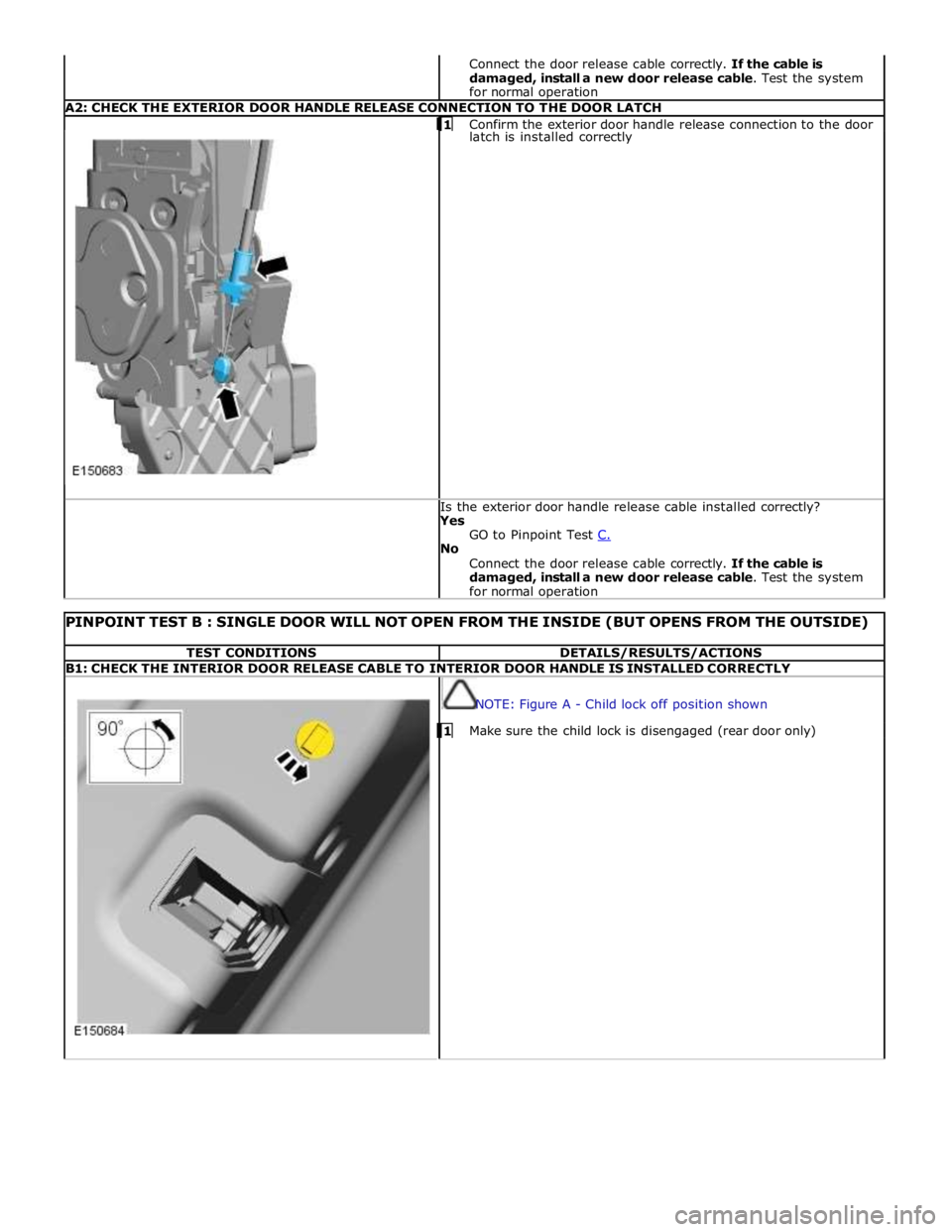
for normal operation A2: CHECK THE EXTERIOR DOOR HANDLE RELEASE CONNECTION TO THE DOOR LATCH 1 Confirm the exterior door handle release connection to the door latch is installed correctly Is the exterior door handle release cable installed correctly?
Yes
GO to Pinpoint Test C. No
Connect the door release cable correctly. If the cable is
damaged, install a new door release cable. Test the system
for normal operation
PINPOINT TEST B : SINGLE DOOR WILL NOT OPEN FROM THE INSIDE (BUT OPENS FROM THE OUTSIDE) TEST CONDITIONS DETAILS/RESULTS/ACTIONS B1: CHECK THE INTERIOR DOOR RELEASE CABLE TO INTERIOR DOOR HANDLE IS INSTALLED CORRECTLY
NOTE: Figure A - Child lock off position shown 1 Make sure the child lock is disengaged (rear door only)
Page 2503 of 3039
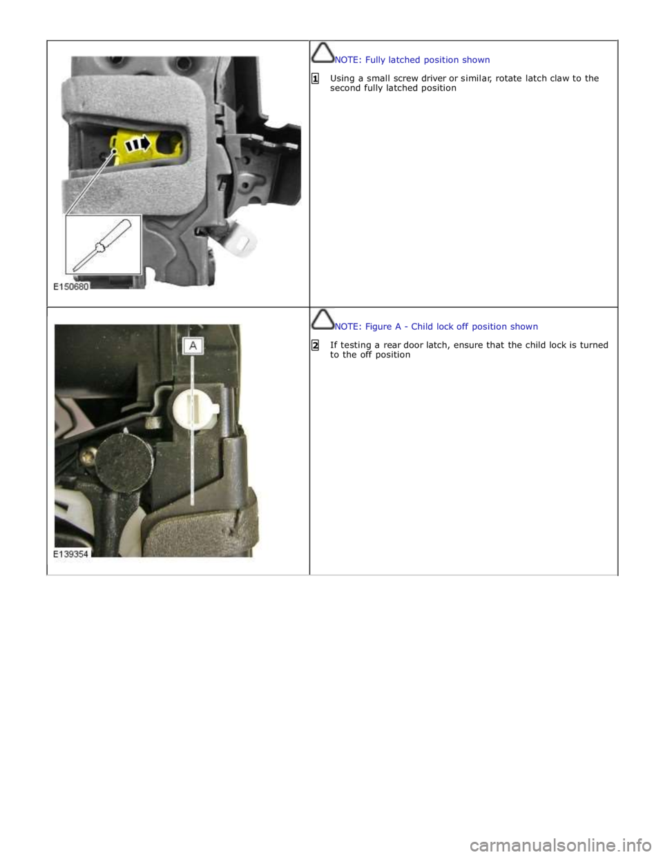
NOTE: Fully latched position shown
1 Using a small screw driver or similar, rotate latch claw to the
second fully latched position
NOTE: Figure A - Child lock off position shown
2 If testing a rear door latch, ensure that the child lock is turned
to the off position
Page 2593 of 3039

Safety Belt System - Safety Belt System - Overview
Description and Operation
Authoring Template
OVERVIEW Published: 11-May-2011
A three point safety belt is fitted to all seating positions. Each safety belt retractor incorporates an emergency locking feature.
The emergency locking retractor incorporates 2 mechanical inertia devices. One inertia device activates if the safety belt is
subjected to a sharp pull. The second inertia device activates if the vehicle is subject to a sudden deceleration or is on a
severe incline.
North American Specification (NAS) safety belt retractors also include an automatic locking feature. The Automatic Locking
Retractor (ALR) is fitted to all passenger seating positions and allows the safety belt to be tensioned to aid the safe fitment
of child or booster seats. For additional information, refer to the Owners Handbook.
NAS vehicles are also fitted with a belt tension sensor on the front passenger seat. The belt tension sensor is incorporated
into the seat belt lower anchorage and is attached to the seat frame by an M10 Torx head bolt. The belt tension sensor forms
part of the SRS (supplemental restraint system) occupancy detection and classification feature.
The center rear safety belt features a mini-buckle lower anchorage. The mini-buckle is disengaged by inserting a suitable tool
into the small aperture on the front face of the housing.
To aid the fitment of child seats, 3 tethers are located on the rear parcel shelf. Each tether is attached to the parcel shelf with
an M10 Torx head bolt.
A safety belt warning indicator is located in the instrument cluster to remind front seat passengers to fasten their safety belts.
The warning indicator will illuminate if the safety belt of an occupied front seat is not fastened.
Refer to: Instrument Cluster (413-01, Description and Operation).
Page 2597 of 3039
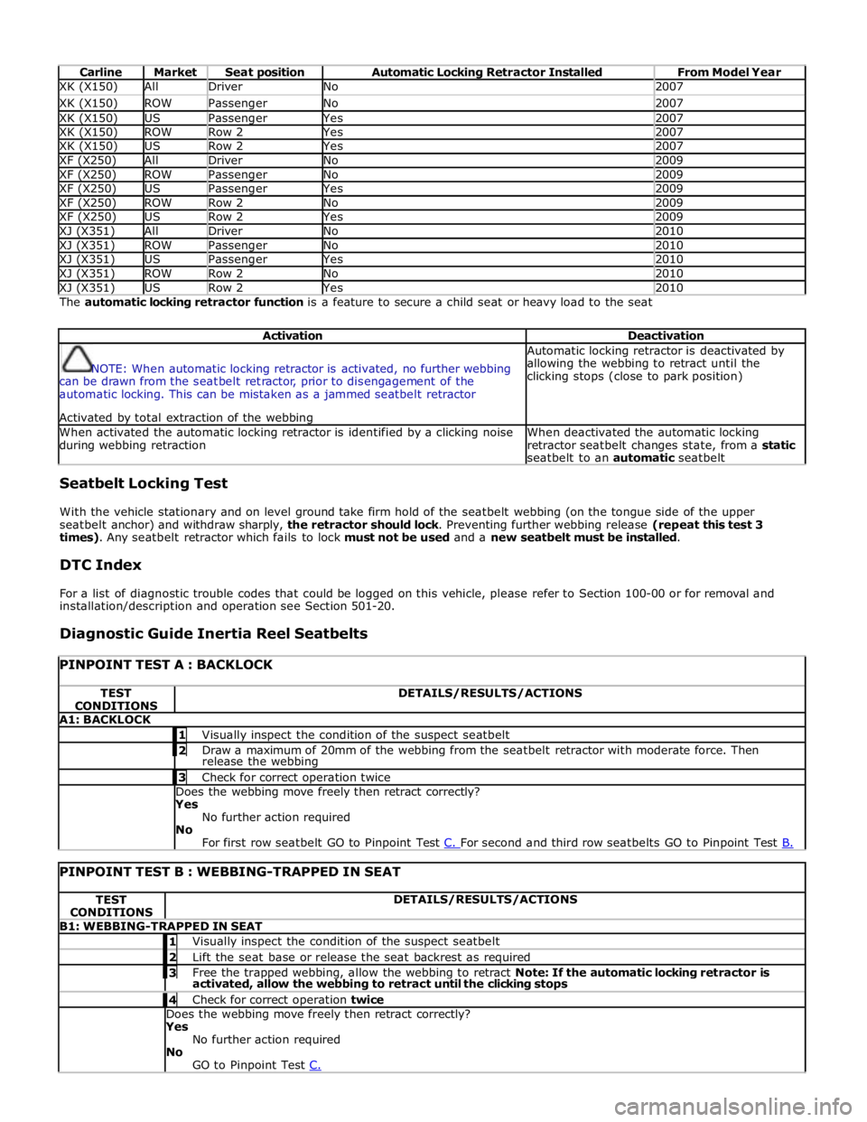
Carline Market Seat position Automatic Locking Retractor Installed From Model Year XK (X150) All Driver No 2007 XK (X150) ROW Passenger No 2007 XK (X150) US Passenger Yes 2007 XK (X150) ROW Row 2 Yes 2007 XK (X150) US Row 2 Yes 2007 XF (X250) All Driver No 2009 XF (X250) ROW Passenger No 2009 XF (X250) US Passenger Yes 2009 XF (X250) ROW Row 2 No 2009 XF (X250) US Row 2 Yes 2009 XJ (X351) All Driver No 2010 XJ (X351) ROW Passenger No 2010 XJ (X351) US Passenger Yes 2010 XJ (X351) ROW Row 2 No 2010 XJ (X351) US Row 2 Yes 2010 The automatic locking retractor function is a feature to secure a child seat or heavy load to the seat
Activation Deactivation
NOTE: When automatic locking retractor is activated, no further webbing
can be drawn from the seatbelt retractor, prior to disengagement of the
automatic locking. This can be mistaken as a jammed seatbelt retractor
Activated by total extraction of the webbing Automatic locking retractor is deactivated by
allowing the webbing to retract until the
clicking stops (close to park position) When activated the automatic locking retractor is identified by a clicking noise
during webbing retraction When deactivated the automatic locking
retractor seatbelt changes state, from a static
seatbelt to an automatic seatbelt Seatbelt Locking Test
With the vehicle stationary and on level ground take firm hold of the seatbelt webbing (on the tongue side of the upper
seatbelt anchor) and withdraw sharply, the retractor should lock. Preventing further webbing release (repeat this test 3
times). Any seatbelt retractor which fails to lock must not be used and a new seatbelt must be installed.
DTC Index
For a list of diagnostic trouble codes that could be logged on this vehicle, please refer to Section 100-00 or for removal and
installation/description and operation see Section 501-20.
Diagnostic Guide Inertia Reel Seatbelts
PINPOINT TEST A : BACKLOCK TEST
CONDITIONS DETAILS/RESULTS/ACTIONS A1: BACKLOCK 1 Visually inspect the condition of the suspect seatbelt 2 Draw a maximum of 20mm of the webbing from the seatbelt retractor with moderate force. Then release the webbing 3 Check for correct operation twice Does the webbing move freely then retract correctly?
Yes
No further action required
No
For first row seatbelt GO to Pinpoint Test C. For second and third row seatbelts GO to Pinpoint Test B.
PINPOINT TEST B : WEBBING-TRAPPED IN SEAT TEST
CONDITIONS DETAILS/RESULTS/ACTIONS B1: WEBBING-TRAPPED IN SEAT 1 Visually inspect the condition of the suspect seatbelt 2 Lift the seat base or release the seat backrest as required 3 Free the trapped webbing, allow the webbing to retract Note: If the automatic locking retractor is activated, allow the webbing to retract until the clicking stops 4 Check for correct operation twice Does the webbing move freely then retract correctly?
Yes
No further action required
No
GO to Pinpoint Test C.
Page 2615 of 3039
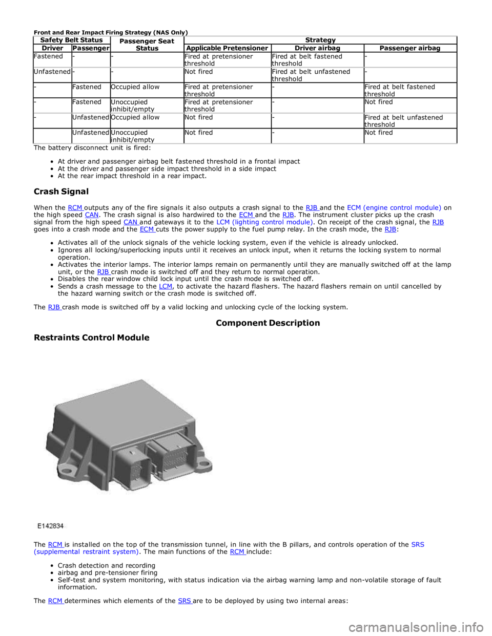
Driver Passenger Applicable Pretensioner Driver airbag Passenger airbag Fastened - -
Fired at pretensioner
threshold Fired at belt fastened
threshold - Unfastened - - Not fired
Fired at belt unfastened
threshold - - Fastened Occupied allow
Fired at pretensioner
threshold -
Fired at belt fastened
threshold - Fastened
Unoccupied inhibit/empty Fired at pretensioner
threshold - Not fired - Unfastened Occupied allow Not fired -
Fired at belt unfastened
threshold Unfastened
Unoccupied inhibit/empty Not fired - Not fired The battery disconnect unit is fired:
At driver and passenger airbag belt fastened threshold in a frontal impact
At the driver and passenger side impact threshold in a side impact
At the rear impact threshold in a rear impact.
Crash Signal
When the RCM outputs any of the fire signals it also outputs a crash signal to the RJB and the ECM (engine control module) on the high speed CAN. The crash signal is also hardwired to the ECM and the RJB. The instrument cluster picks up the crash signal from the high speed CAN and gateways it to the LCM (lighting control module). On receipt of the crash signal, the RJB goes into a crash mode and the ECM cuts the power supply to the fuel pump relay. In the crash mode, the RJB: Activates all of the unlock signals of the vehicle locking system, even if the vehicle is already unlocked.
Ignores all locking/superlocking inputs until it receives an unlock input, when it returns the locking system to normal
operation.
Activates the interior lamps. The interior lamps remain on permanently until they are manually switched off at the lamp
unit, or the RJB crash mode is switched off and they return to normal operation. Disables the rear window child lock input until the crash mode is switched off.
Sends a crash message to the LCM, to activate the hazard flashers. The hazard flashers remain on until cancelled by the hazard warning switch or the crash mode is switched off.
The RJB crash mode is switched off by a valid locking and unlocking cycle of the locking system.
Restraints Control Module Component Description
The RCM is installed on the top of the transmission tunnel, in line with the B pillars, and controls operation of the SRS (supplemental restraint system). The main functions of the RCM include:
Crash detection and recording
airbag and pre-tensioner firing
Self-test and system monitoring, with status indication via the airbag warning lamp and non-volatile storage of fault
information.
The RCM determines which elements of the SRS are to be deployed by using two internal areas: