2010 JAGUAR XFR set clock
[x] Cancel search: set clockPage 50 of 3039
disconnected, a Radio Code Saver will allow sufficient current to pass to maintain the radio receiver/cassette player/mini disc
player and compact disc player memory, operate the clock and supply the door operated interior lights while isolating the
battery in the event of a short circuit.
Reconnecting the Battery
WARNING: If the battery has been on bench charge the cells may be giving off explosive hydrogen gas. Avoid creating
sparks, and if in doubt cover the vent plugs or covers with a damp cloth.
Always make sure that all electrical systems are switched OFF before reconnecting the battery to avoid causing sparks or
damage to sensitive electrical equipment.
Always reconnect the battery positive lead first and the negative last, ensuring that there is a good electrical contact and the
battery terminals are secure.
Restart the clock (where installed) and set it to the correct time.
Enter the radio receiver/cassette player/mini disc player and compact disc player keycodes and preset' frequencies, if known.
Following reconnection of the battery, the engine should be allowed to idle until it has reached normal operating temperature
as the stored idle and drive values contained within the ECM have been lost. Allow the vehicle to idle for a further three
minutes. Drive the vehicle at constant speeds of approximately 48 km/h (30 mph), 64 km/h (40 mph), 80 km/h (50 mph), 96
km/h (60 mph) and 112 km/h (70 mph) for three minutes each. This will allow the ECM to relearn idle and drive values, and
may cause driveability concerns if the procedure is not carried out.
Connecting a Slave Battery Using Jump Leads
WARNING: If the slave battery has recently been charged and is gassing, cover the vent plugs or covers with a damp
cloth to reduce the risk of explosion should arcing occur when connecting the jump leads.
CAUTIONS:
A discharged battery condition may have been caused by an electrical short circuit. If this condition exists there will be
an apparently live circuit on the vehicle even when all circuits are switched off. This can cause arcing when the jump leads are
connected.
Whilst it is not recommended that the vehicle is jump started, it is recognized that this may occasionally be the only
practical way to mobilize a vehicle. In such an instance the discharged battery must be recharged immediately after jump
starting to avoid permanent damage.
Always make sure that the jump leads are adequate for the task. Heavy duty cables must be used.
Always make sure that the slave battery is of the same voltage as the vehicle battery. The batteries must be connected
in parallel.
Always make sure that switchable electric circuits are switched off before connecting jump leads. This reduces the risk
of sparks occurring when the final connection is made.
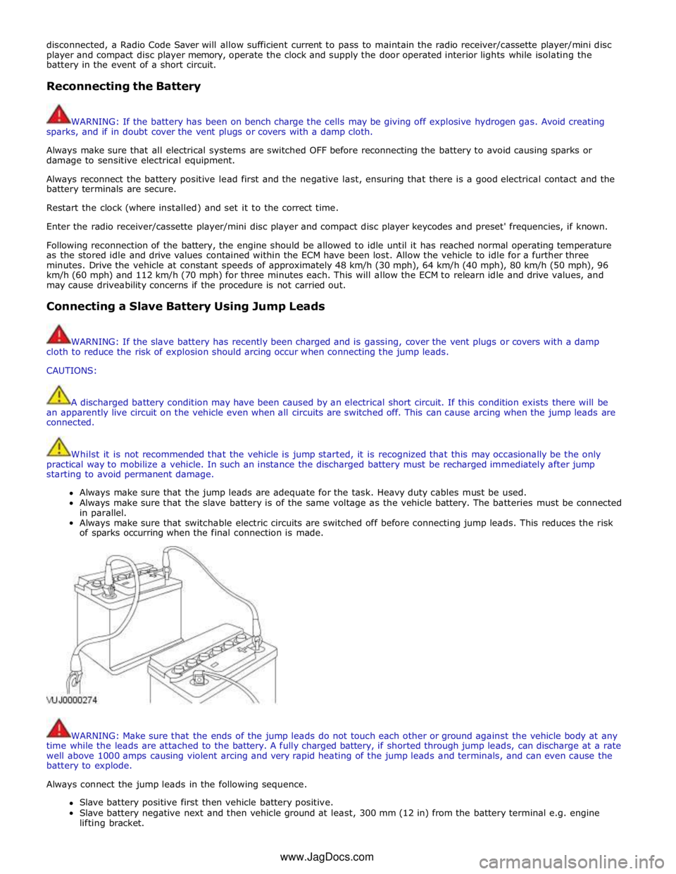
WARNING: Make sure that the ends of the jump leads do not touch each other or ground against the vehicle body at any
time while the leads are attached to the battery. A fully charged battery, if shorted through jump leads, can discharge at a rate
well above 1000 amps causing violent arcing and very rapid heating of the jump leads and terminals, and can even cause the
battery to explode.
Always connect the jump leads in the following sequence.
Slave battery positive first then vehicle battery positive.
Slave battery negative next and then vehicle ground at least, 300 mm (12 in) from the battery terminal e.g. engine
lifting bracket. www.JagDocs.com
Page 191 of 3039

DTC Description Possible Causes Action B10A0-11
Wiper/ Washer Switch -
Circuit short to ground
Wash/wipe circuit - short to
ground
Refer to the electrical circuit diagrams and check
wash/wipe circuit for short to ground B10A0-15
Wiper/ Washer Switch -
Circuit short to battery
or open
Wash/wipe circuit - short to
power, open circuit
Carry out any pinpoint tests associated with this
DTC using the manufacturer approved diagnostic
system. Refer to the electrical circuit diagrams
and check wash/wipe circuit for short to power,
open circuit B10A6-11
Main Light Switch -
Circuit short to ground
Master lighting switch circuit
- short to ground
Refer to the electrical circuit diagrams and check
master lighting switch circuit for short to ground B10A6-15
Main Light Switch -
Circuit short to battery
or open
Master lighting switch circuit
- short to power, open
circuit
Carry out any pinpoint tests associated with this
DTC using the manufacturer approved diagnostic
system. Refer to the electrical circuit diagrams
and check master lighting switch circuit for short
to power, open circuit B112B-87
Steering Wheel Module -
Missing message
Steering wheel module
failure - slave node not
responding
Carry out any pinpoint tests associated with this
DTC using the manufacturer approved diagnostic
system. Refer to the electrical circuit diagrams
and check the clockspring LIN circuit for short,
open circuit. Suspect the clockspring, check and
install a new clockspring as required, refer to the
new module/component installation note at the
top of the DTC Index B115C-7A Transfer Fuel Pump -
Fluid leak or seal failure
Fuel pump system fault
Check for fuel system jet pump or jet pump fuel
level sensor fault B1A85-15
Ambient Light Sensor -
Circuit short to battery
or open
Autolamp sensor circuit -
short to power, open circuit
Carry out any pinpoint tests associated with this
DTC using the manufacturer approved diagnostic
system. Refer to the electrical circuit diagrams
and check autolamp sensor circuit for short to
power, open circuit B1B01-00
Key Transponder - No
sub type information
Operator only cycles one key
During transponder key
programming the instrument
cluster, smartcard docking
station or key loses
power/circuit failure
Faulty key during key
programming
Unable to program
transponder key due to
noise/EMC related error
Ensure all keys to be programmed are available.
Refer to electrical circuit diagrams and check
power and ground supply circuits to all relevant
modules. Replace faulty key and repeat key
programming. Check CAN network for
interference/EMC related issues B1B01-05
Key Transponder -
System programming
failures
Error following SCU
replacement
Smartcard docking station
power and ground supply
circuits - short, open circuit
LIN fault
Instrument cluster power
and ground supply circuits -
short, open circuit
Carry out any pinpoint tests associated with this
DTC using the manufacturer approved diagnostic
system. Perform the Immobilisation application
from the Set-up menu using the manufacturer
approved diagnostic system. Refer to the
electrical circuit diagrams and check smartcard
docking station power and ground supply circuits
for short, open circuit and instrument cluster
power and ground supply circuits for short, open
circuit. Check LIN communications between
smartcard docking station and instrument cluster B1B01-51
Key Transponder - Not
programmed
LIN fault
Instrument cluster power
and ground supply circuits -
short, open circuit
Key fault
Smartcard docking station
power and ground supply
circuits - short, open circuit
Attempted to program a non
Carry out any pinpoint tests associated with this
DTC using the manufacturer approved diagnostic
system. Check LIN communications between
smartcard docking station and instrument
cluster. Refer to the electrical circuit diagrams
and check smartcard docking station power and
ground supply circuits for short, open circuit and
instrument cluster power and ground supply
circuits for short, open circuit. Confirm www.JagDocs.com
Page 782 of 3039
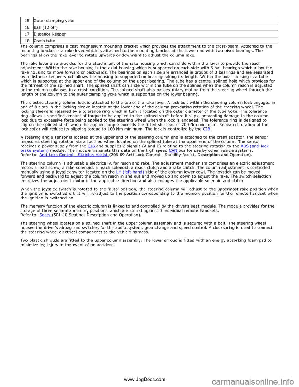
16 Ball (12 off) 17 Distance keeper 18 Crash tube The column comprises a cast magnesium mounting bracket which provides the attachment to the cross-beam. Attached to the
mounting bracket is a rake lever which is attached to the mounting bracket at the lower end with two pivot bearings. The
bearings allow the rake lever to rotate upwards or downward to adjust the column rake.
The rake lever also provides for the attachment of the rake housing which can slide within the lever to provide the reach
adjustment. Within the rake housing is the axial housing which is supported on each side with 6 ball bearings which allow the
rake housing to move forward or backwards. The bearings on each side are arranged in groups of 3 bearings and are separated
by a distance keeper which allows the housing to supported on bearings along its length. Within the axial housing is a tube
which is supported at the upper end of the column on the upper bearing. The tube has a central splined hole which provides for
the fitment of the splined shaft. The splined shaft can slide within the tube on the splines when the column reach is adjusted
or the column collapses in a crash condition. The splined shaft also passes rotary motion from the steering wheel through the
length of the column to the outer clamping yoke which is supported on the lower bearing.
The electric steering column lock is attached to the top of the rake lever. A lock bolt within the steering column lock engages in
one of 8 slots in the locking sleeve located at the lower end of the column preventing rotation of the steering wheel. The
locking sleeve is retained by a tolerance ring which in turn is located on the outer diameter of the tube yoke. The tolerance
ring allows a specified amount of torque to be applied to the splined shaft before it slips, preventing damage to the column
lock due to excessive force being applied to the steering wheel when the lock is engaged. The tolerance ring is designed to
slip on the splined shaft when the applied torque exceeds the fitted slip load of 200 Nm minimum. Repeated rotation of the
lock collar will reduce its slipping torque to 100 Nm minimum. The lock is controlled by the CJB.
A steering angle sensor is located at the upper end of the steering column and is attached to the crash adaptor. The sensor
measures steering rotation via a toothed wheel located on the splined tube at the upper end of the column. The sensor
receives a power supply from the CJB and supplies 2 signals (A and B) relating to the steering rotation to the ABS (anti-lock brake system) module. The module transmits this data on the high speed CAN bus for use by other vehicle systems. Refer to: Anti-Lock Control - Stability Assist (206-09 Anti-Lock Control - Stability Assist, Description and Operation).
The steering column is adjustable electrically, for reach and rake. The adjustment mechanism comprises an electric adjustment
motor, a lead screw, a rake solenoid, a reach solenoid, a reach clutch and a rake clutch. The column adjustment is controlled
manually using a joystick switch located on the LH (left-hand) side of the column lower cowl. The joystick can be moved
forward and backward to adjust the column reach in and out and moved up and down to adjust the rake. The switch selection
energizes the adjustment motor in the applicable direction and also engages the applicable solenoid and clutch.
When the joystick switch is rotated to the 'auto' position, the steering column will adjust to the uppermost rake position when
the ignition is switched off. It will re-adjust to the position corresponding to the memory position for the remote handset when
the ignition is switched on.
The memory function of the electric column is linked to and controlled by the driver's seat module. The module provides for the
storage of three separate memory positions which are stored against 3 individual remote handsets.
Refer to: Seats (501-10 Seating, Description and Operation).
The steering wheel locates on a splined shaft in the upper column assembly and is secured with a bolt. The steering wheel
houses the driver's airbag and switches for the audio system, gear change and speed control. A clockspring is used to connect
the steering wheel electrical components to the vehicle harness.
Two plastic shrouds are fitted to the upper column assembly. The lower shroud is fitted with an energy absorbing foam pad to
minimize leg injury in the event of an accident.
www.JagDocs.com
Page 795 of 3039
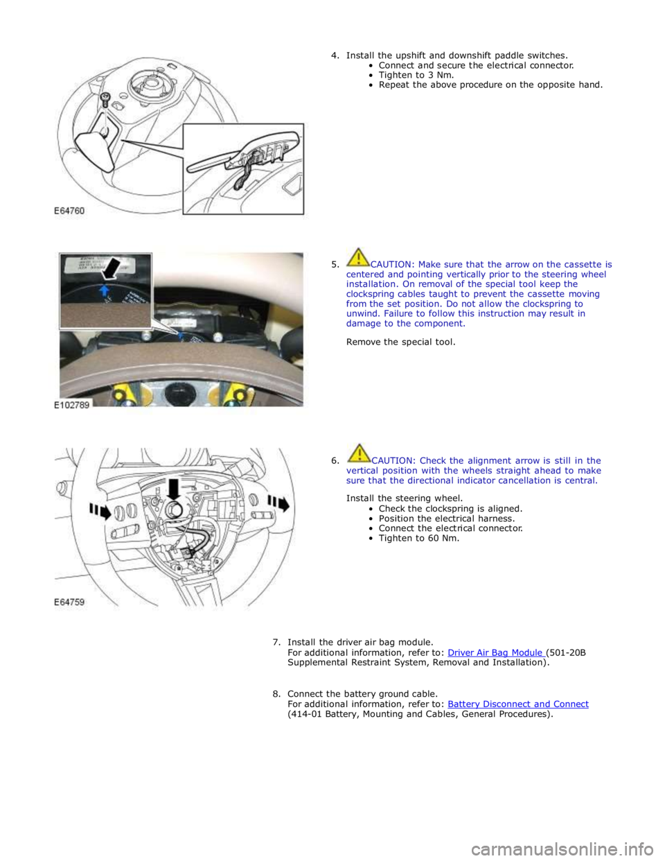
4. Install the upshift and downshift paddle switches.
Connect and secure the electrical connector.
Tighten to 3 Nm.
Repeat the above procedure on the opposite hand.
5. CAUTION: Make sure that the arrow on the cassette is
centered and pointing vertically prior to the steering wheel
installation. On removal of the special tool keep the
clockspring cables taught to prevent the cassette moving
from the set position. Do not allow the clockspring to
unwind. Failure to follow this instruction may result in
damage to the component.
Remove the special tool.
6. CAUTION: Check the alignment arrow is still in the
vertical position with the wheels straight ahead to make
sure that the directional indicator cancellation is central.
Install the steering wheel.
Check the clockspring is aligned.
Position the electrical harness.
Connect the electrical connector.
Tighten to 60 Nm.
7. Install the driver air bag module.
For additional information, refer to: Driver Air Bag Module (501-20B Supplemental Restraint System, Removal and Installation).
8. Connect the battery ground cable.
For additional information, refer to: Battery Disconnect and Connect (414-01 Battery, Mounting and Cables, General Procedures).
Page 802 of 3039
Turn signal indicators
Side lamps
Headlamps
Auto lamps
High/low beam
Headlamp flash
Headlamp timer
Trip computer.
The switch is located in a slot in the clockspring and secured with 2 plastic clips.
RH Multifunction Switch
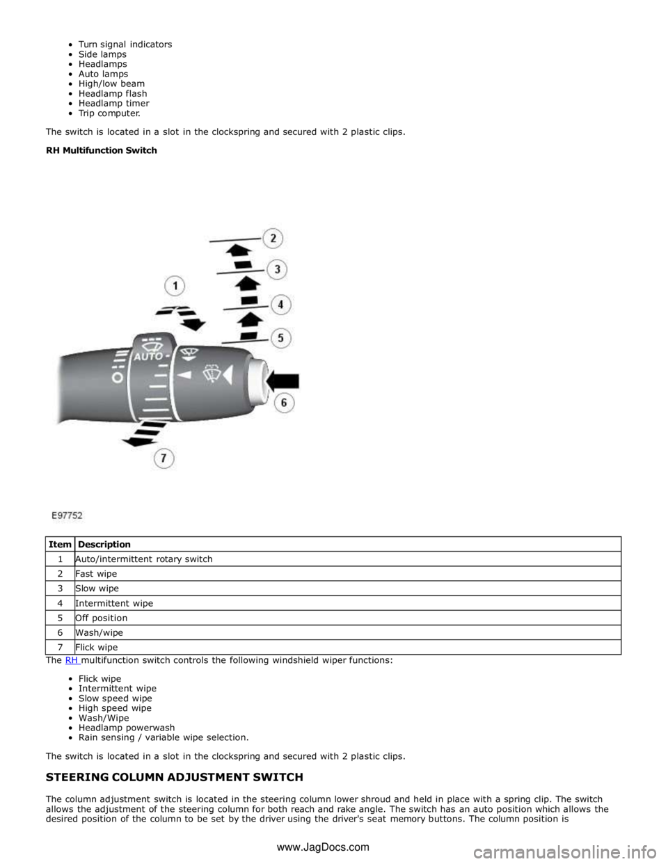
The RH multifunction switch controls the following windshield wiper functions: Flick wipe
Intermittent wipe
Slow speed wipe
High speed wipe
Wash/Wipe
Headlamp powerwash
Rain sensing / variable wipe selection.
The switch is located in a slot in the clockspring and secured with 2 plastic clips.
STEERING COLUMN ADJUSTMENT SWITCH
The column adjustment switch is located in the steering column lower shroud and held in place with a spring clip. The switch
allows the adjustment of the steering column for both reach and rake angle. The switch has an auto position which allows the
desired position of the column to be set by the driver using the driver's seat memory buttons. The column position is Item Description 1 Auto/intermittent rotary switch 2 Fast wipe 3 Slow wipe 4 Intermittent wipe 5 Off position 6 Wash/wipe 7 Flick wipe www.JagDocs.com
Page 803 of 3039

automatically reset once the applicable remote handset has been detected by the vehicle security systems.
STEERING WHEEL HEATER
On certain models the rim of the steering wheel contains a heater element. Operation of the heater is selected using the
Touch Screen Display (TSD).
The heater temperature is controlled by a heated steering wheel control module located within the steering wheel. Power for
the heater element is supplied to the steering wheel via 2 contacts on the clockspring and a slip ring mounted on the steering
wheel.
Page 1531 of 3039
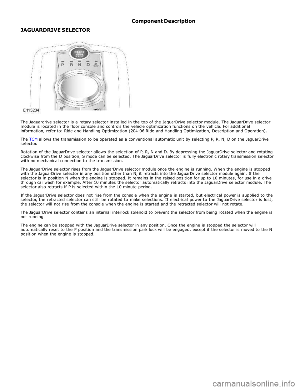
selector.
Rotation of the JaguarDrive selector allows the selection of P, R, N and D. By depressing the JaguarDrive selector and rotating
clockwise from the D position, S mode can be selected. The JaguarDrive selector is fully electronic rotary transmission selector
with no mechanical connection to the transmission.
The JaguarDrive selector rises from the JaguarDrive selector module once the engine is running. When the engine is stopped
with the JaguarDrive selector in any position other than N, it retracts into the JaguarDrive selector module again. If the
selector is in position N when the engine is stopped, it remains in the raised position for up to 10 minutes, for use in a drive
through car wash for example. After 10 minutes the selector automatically retracts into the JaguarDrive selector module. The
selector also retracts if P is selected within the 10 minute period.
If the JaguarDrive selector does not rise from the console when the engine is started, but electrical power is supplied to the
selector, the retracted selector can still be rotated to make selections. If electrical power to the JaguarDrive selector is lost,
the selector will not rise from the console when the engine is started and the retracted selector will not rotate.
The JaguarDrive selector contains an internal interlock solenoid to prevent the selector from being rotated when the engine is
not running.
The engine can be stopped with the JaguarDrive selector in any position. Once the engine is stopped the selector will
automatically reset to the P position and the transmission park lock will be engaged, except if the selector is moved to the N
position when the engine is stopped.
Page 1639 of 3039

Published: 11-May-2011
Speed Control - V8 5.0L Petrol/V8 S/C 5.0L Petrol - Speed Control - Overview
Description and Operation
OVERVIEW
Speed Control
The speed control system is integrated with the engine management system and uses fueling intervention to automatically
maintain a set vehicle speed. Once engaged, the system can also be used to accelerate the vehicle without using the
accelerator pedal.
The speed control system comprises the following components:
On/Off/Suspend switch
'+' and '-' (set/accelerate and decelerate) steering wheel switches
Resume switch
Clock spring
Speed control warning indicator.
Adaptive Speed Control
The adaptive speed control system uses a forward looking radar sensor to scan the road ahead, looking for objects that are
moving at a different rate to itself. When a target is identified the adaptive speed control system will monitor the time gap
between it and the target vehicle. When that gap falls below a set driver selected level the adaptive speed control system will
intervene slowing the vehicle by backing off the throttle and/ or applying the brakes, until the correct gap is attained.
The adaptive speed control system comprises the following components:
Adaptive speed control sensor
Adaptive speed control module
Steering wheel control switches
ECM (engine control module)
Electric throttle actuator
ABS (anti-lock brake system) module and pump
Adaptive speed control warning indicator (in the instrument cluster).