2010 JAGUAR XFR service schedule
[x] Cancel search: service schedulePage 49 of 3039

General Information - General Service Information
Description and Operation
Repairs and Replacements Published: 28-Dec-2012
When service parts are required, it is essential that only genuine Jaguar/Daimler replacements are used.
Attention is drawn to the following points concerning repairs and the installation of replacement parts and accessories:
Safety features embodied in the vehicle may be impaired if other than genuine parts are installed. In certain territories,
legislation prohibits the installation of parts which are not produced to the vehicle manufacturer's specification.
Torque wrench setting figures given in this manual must be strictly adhered to. Locking devices, where specified, must
be installed. If the efficiency of a locking device is impaired during removal it must be renewed.
Owners purchasing accessories while travelling abroad should make sure that the accessory and its installed location on
the vehicle conform to mandatory requirements existing in their country of origin.
The vehicle warranty may be invalidated by the installation of other than genuine Jaguar/Daimler parts. All
Jaguar/Daimler replacements have the full backing of the factory warranty.
Jaguar/Daimler dealers are obliged to supply only genuine service parts.
Vehicle Specifications
Purchasers are advised that the specification details set out in this manual apply to a range of vehicles and not to any specific
one. For the specification of a particular vehicle, purchasers should consult their dealer.
The Manufacturer reserves the right to vary the specifications, with or without notice, and at such times and in such manner as
the Manufacturer thinks fit. Major as well as minor changes may be involved, in accordance with the Manufacturer's policy of
continuous improvement.
Whilst every effort is made to make sure the accuracy of the particulars contained in this manual, neither the Manufacturer nor
the Dealer, by whom the manual is supplied, shall in any circumstances be held liable for any inaccuracy or the consequences
thereof.
Service Repair Operation Numbering
A master index of numbered operations has been compiled for universal application to all vehicles manufactured by Jaguar
Land Rover Limited.
Each operation is allocated a number from the master index and cross-refers with an identical number in the Repair Operation
Times schedule. The number consists of six digits arranged in three pairs.
Each maintenance procedure in this manual is described in the sequence necessary to complete the operation in the minimum
time, as specified in the Repair Operation Times schedule.
References to Bank-1 and Bank-2
References to Bank-1 and Bank-2 are made with regard to the engine. When viewed from the flywheel the right-hand bank will
be Bank-1 and the left-hand bank will be Bank-2.
Special Tools
Any special tools and equipment required to perform a maintenance procedure, are shown at the beginning of each procedure.
When possible, illustrations are given to assist in identifying the tool needed.
Disconnecting/Connecting the Battery
Always stop the engine before disconnecting the battery negative lead and make sure the battery positive lead is isolated i.e.
wrapped in a suitable cloth.
WARNING: Radio code saving devices must not be used when conducting work on Air Bag or Fuel systems. It must be
noted that, when using these devices, the vehicle electrical system is still live albeit with a reduced current flow.
NOTE: Before disconnecting the battery make sure that the radio receiver/cassette player/mini disc player and compact
disc player keycodes are known and, that no data is required from the Engine Control Module (ECM) as battery disconnection
will erase any fault codes and idle/drive values held in the Keep Alive Memory (KAM).
Always disconnect the battery before commencing repair operations which require:
The vehicle to be jacked up
Work on the engine
Work underneath the vehicle
Arc welding
Alternatively a Radio Code Saver may be used, when not working on the Air Bag or Fuel systems. With the battery
Page 2754 of 3039

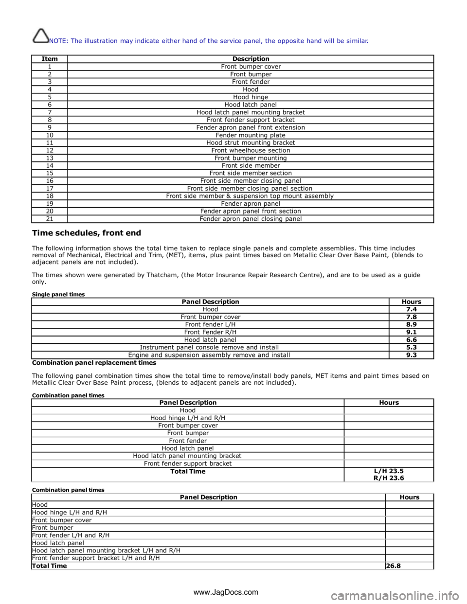
NOTE: The illustration may indicate either hand of the service panel, the opposite hand will be similar.
Item Description 1 Front bumper cover 2 Front bumper 3 Front fender 4 Hood 5 Hood hinge 6 Hood latch panel 7 Hood latch panel mounting bracket 8 Front fender support bracket 9 Fender apron panel front extension 10 Fender mounting plate 11 Hood strut mounting bracket 12 Front wheelhouse section 13 Front bumper mounting 14 Front side member 15 Front side member section 16 Front side member closing panel 17 Front side member closing panel section 18 Front side member & suspension top mount assembly 19 Fender apron panel 20 Fender apron panel front section 21 Fender apron panel closing panel Time schedules, front end
The following information shows the total time taken to replace single panels and complete assemblies. This time includes
removal of Mechanical, Electrical and Trim, (MET), items, plus paint times based on Metallic Clear Over Base Paint, (blends to
adjacent panels are not included).
The times shown were generated by Thatcham, (the Motor Insurance Repair Research Centre), and are to be used as a guide
only.
Single panel times
Panel Description Hours Hood 7.4 Front bumper cover 7.8 Front fender L/H 8.9 Front Fender R/H 9.1 Hood latch panel 6.6 Instrument panel console remove and install 5.3 Engine and suspension assembly remove and install 9.3 Combination panel replacement times
The following panel combination times show the total time to remove/install body panels, MET items and paint times based on
Metallic Clear Over Base Paint process, (blends to adjacent panels are not included).
Combination panel times
Panel Description Hours Hood Hood hinge L/H and R/H Front bumper cover Front bumper Front fender Hood latch panel Hood latch panel mounting bracket Front fender support bracket Total Time L/H 23.5
R/H 23.6 Combination panel times
Panel Description Hours Hood Hood hinge L/H and R/H Front bumper cover Front bumper Front fender L/H and R/H Hood latch panel Hood latch panel mounting bracket L/H and R/H Front fender support bracket L/H and R/H Total Time 26.8 www.JagDocs.com
Page 2843 of 3039

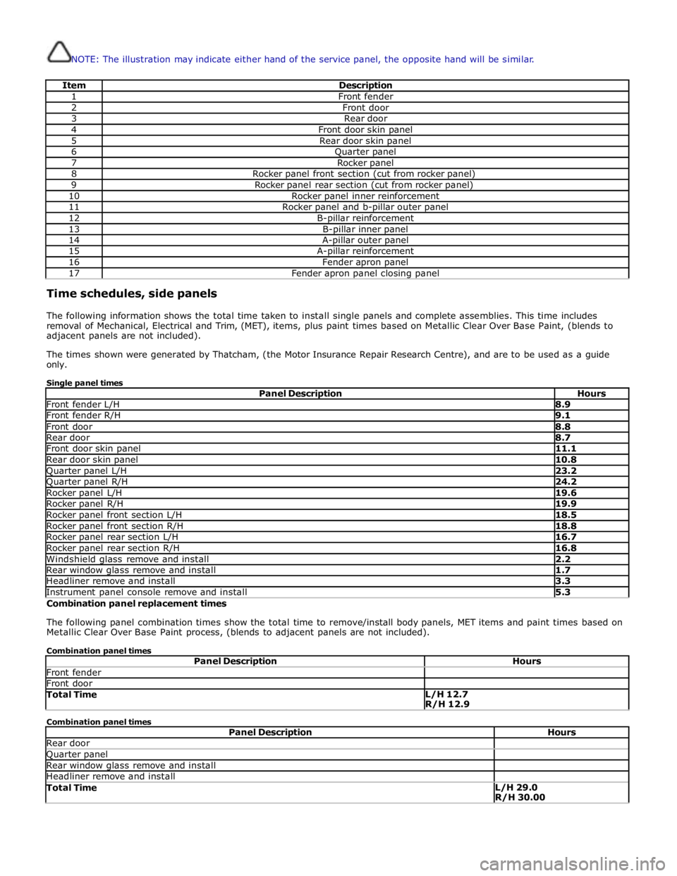
NOTE: The illustration may indicate either hand of the service panel, the opposite hand will be similar.
Item Description 1 Front fender 2 Front door 3 Rear door 4 Front door skin panel 5 Rear door skin panel 6 Quarter panel 7 Rocker panel 8 Rocker panel front section (cut from rocker panel) 9 Rocker panel rear section (cut from rocker panel) 10 Rocker panel inner reinforcement 11 Rocker panel and b-pillar outer panel 12 B-pillar reinforcement 13 B-pillar inner panel 14 A-pillar outer panel 15 A-pillar reinforcement 16 Fender apron panel 17 Fender apron panel closing panel Time schedules, side panels
The following information shows the total time taken to install single panels and complete assemblies. This time includes
removal of Mechanical, Electrical and Trim, (MET), items, plus paint times based on Metallic Clear Over Base Paint, (blends to
adjacent panels are not included).
The times shown were generated by Thatcham, (the Motor Insurance Repair Research Centre), and are to be used as a guide
only.
Single panel times
Panel Description Hours Front fender L/H 8.9 Front fender R/H 9.1 Front door 8.8 Rear door 8.7 Front door skin panel 11.1 Rear door skin panel 10.8 Quarter panel L/H 23.2 Quarter panel R/H 24.2 Rocker panel L/H 19.6 Rocker panel R/H 19.9 Rocker panel front section L/H 18.5 Rocker panel front section R/H 18.8 Rocker panel rear section L/H 16.7 Rocker panel rear section R/H 16.8 Windshield glass remove and install 2.2 Rear window glass remove and install 1.7 Headliner remove and install 3.3 Instrument panel console remove and install 5.3 Combination panel replacement times
The following panel combination times show the total time to remove/install body panels, MET items and paint times based on
Metallic Clear Over Base Paint process, (blends to adjacent panels are not included).
Combination panel times
Panel Description Hours Front fender Front door Total Time L/H 12.7
R/H 12.9 Combination panel times
Panel Description Hours Rear door Quarter panel Rear window glass remove and install Headliner remove and install Total Time L/H 29.0
R/H 30.00
Page 2941 of 3039

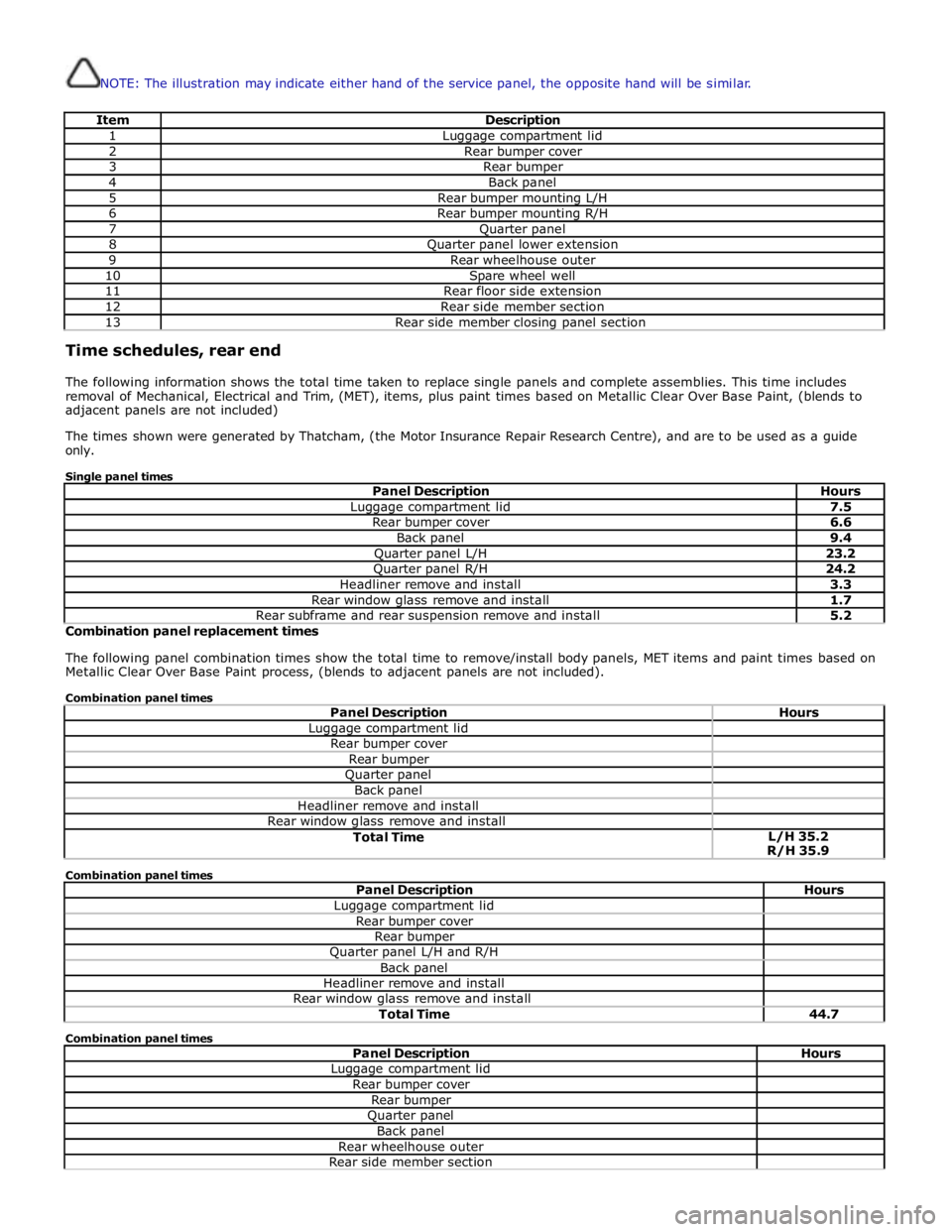
NOTE: The illustration may indicate either hand of the service panel, the opposite hand will be similar.
Item Description 1 Luggage compartment lid 2 Rear bumper cover 3 Rear bumper 4 Back panel 5 Rear bumper mounting L/H 6 Rear bumper mounting R/H 7 Quarter panel 8 Quarter panel lower extension 9 Rear wheelhouse outer 10 Spare wheel well 11 Rear floor side extension 12 Rear side member section 13 Rear side member closing panel section Time schedules, rear end
The following information shows the total time taken to replace single panels and complete assemblies. This time includes
removal of Mechanical, Electrical and Trim, (MET), items, plus paint times based on Metallic Clear Over Base Paint, (blends to
adjacent panels are not included)
The times shown were generated by Thatcham, (the Motor Insurance Repair Research Centre), and are to be used as a guide
only.
Single panel times
Panel Description Hours Luggage compartment lid 7.5 Rear bumper cover 6.6 Back panel 9.4 Quarter panel L/H 23.2 Quarter panel R/H 24.2 Headliner remove and install 3.3 Rear window glass remove and install 1.7 Rear subframe and rear suspension remove and install 5.2 Combination panel replacement times
The following panel combination times show the total time to remove/install body panels, MET items and paint times based on
Metallic Clear Over Base Paint process, (blends to adjacent panels are not included).
Combination panel times
Panel Description Hours Luggage compartment lid Rear bumper cover Rear bumper Quarter panel Back panel Headliner remove and install Rear window glass remove and install Total Time L/H 35.2
R/H 35.9 Combination panel times
Panel Description Hours Luggage compartment lid Rear bumper cover Rear bumper Quarter panel L/H and R/H Back panel Headliner remove and install Rear window glass remove and install Total Time 44.7 Combination panel times
Panel Description Hours Luggage compartment lid Rear bumper cover Rear bumper Quarter panel Back panel Rear wheelhouse outer Rear side member section