2010 JAGUAR XFR drain bolt
[x] Cancel search: drain boltPage 528 of 3039
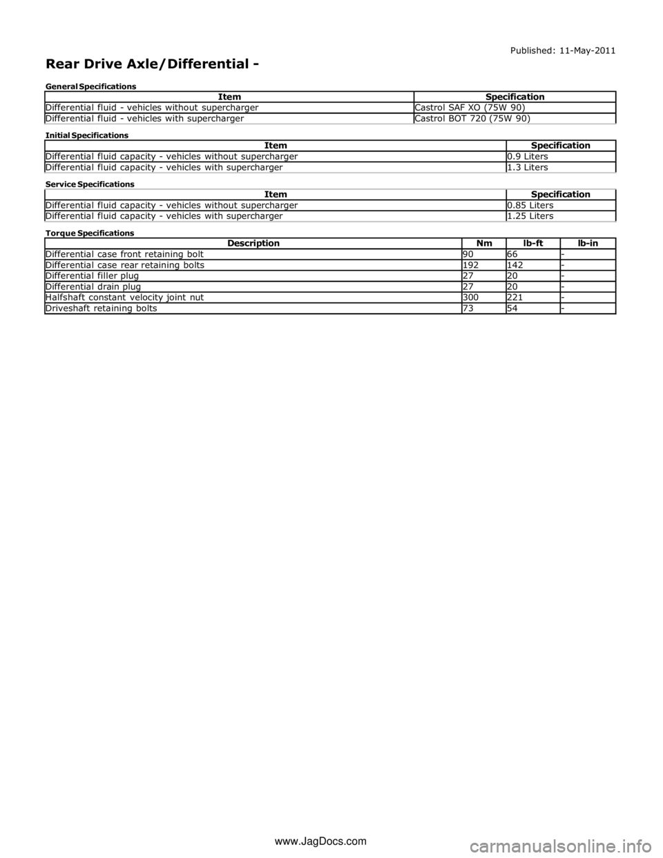
Differential fluid - vehicles without supercharger Castrol SAF XO (75W 90) Differential fluid - vehicles with supercharger Castrol BOT 720 (75W 90) Initial Specifications
Item Specification Differential fluid capacity - vehicles without supercharger 0.9 Liters Differential fluid capacity - vehicles with supercharger 1.3 Liters Service Specifications
Item Specification Differential fluid capacity - vehicles without supercharger 0.85 Liters Differential fluid capacity - vehicles with supercharger 1.25 Liters Torque Specifications
Description Nm lb-ft lb-in Differential case front retaining bolt 90 66 - Differential case rear retaining bolts 192 142 - Differential filler plug 27 20 - Differential drain plug 27 20 - Halfshaft constant velocity joint nut 300 221 - Driveshaft retaining bolts 73 54 - www.JagDocs.com
Page 535 of 3039

Thrust race 7 Shim 8 Thrust plate 9 Dished washer 10 Bolt (10 off) 11 Clutch basket 12 Multi-plate clutch and pressure disc 13 Differential case 14 Screw (2 off) 15 Bearing assembly 16 Oil seal 17 Oil slinger inner 18 Oil slinger outer 19 Input flange 20 Pinion nut 21 Collapsible spacer 22 Shim 23 Bearing assembly 24 Pinion shaft 25 Mounting insulator inner (2 off) 26 Mounting insulator rubber (2 off) 27 Mounting insulator outer (2 off) 28 Carrier 29 Oil seal 30 Drain plug 31 Vent 32 Breather cap 33 Shim 34 Bearing assembly 35 Drive gear 36 Shim 37 RH sun gear 38 Circlip 39 Thrust washer (4 off) 40 Planet gear (4 off) 41 Pin (2 off) 42 Shaft 43 LH sun gear 44 Shim 45 Bearing assembly 46 Shim 47 Dowel (2 off) 48 Bolt (4 off) 49 Reduction gear casing 50 Reduction gear 51 Shaft 52 Temperature sensor 53 O-ring seal 54 Motor 55 Screw (4 off) 56 Cover 57 Output actuator locking pin 58 Bolt (9 off)
Page 813 of 3039
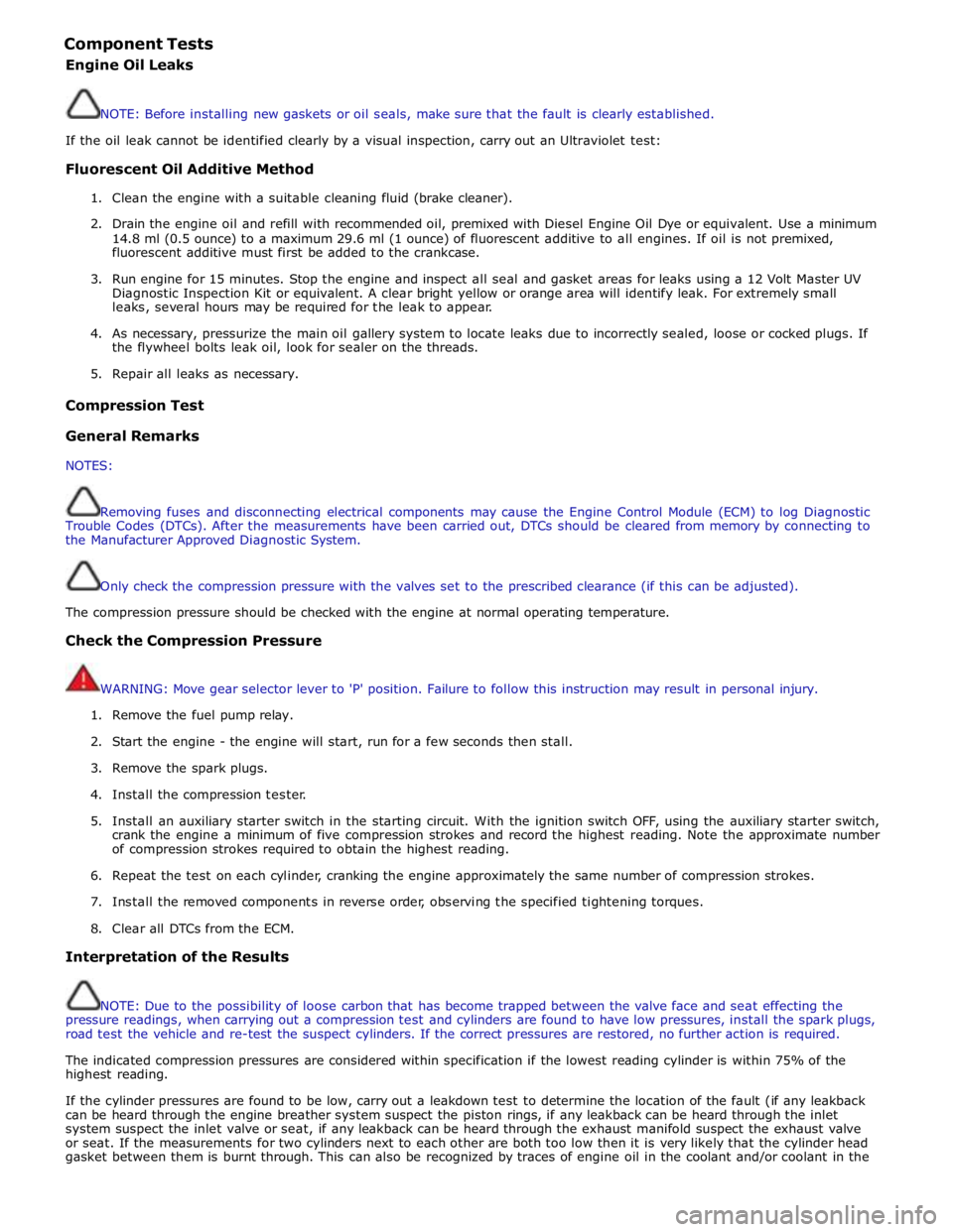
Component Tests
Engine Oil Leaks
NOTE: Before installing new gaskets or oil seals, make sure that the fault is clearly established.
If the oil leak cannot be identified clearly by a visual inspection, carry out an Ultraviolet test:
Fluorescent Oil Additive Method
1. Clean the engine with a suitable cleaning fluid (brake cleaner).
2. Drain the engine oil and refill with recommended oil, premixed with Diesel Engine Oil Dye or equivalent. Use a minimum
14.8 ml (0.5 ounce) to a maximum 29.6 ml (1 ounce) of fluorescent additive to all engines. If oil is not premixed,
fluorescent additive must first be added to the crankcase.
3. Run engine for 15 minutes. Stop the engine and inspect all seal and gasket areas for leaks using a 12 Volt Master UV
Diagnostic Inspection Kit or equivalent. A clear bright yellow or orange area will identify leak. For extremely small
leaks, several hours may be required for the leak to appear.
4. As necessary, pressurize the main oil gallery system to locate leaks due to incorrectly sealed, loose or cocked plugs. If
the flywheel bolts leak oil, look for sealer on the threads.
5. Repair all leaks as necessary.
Compression Test General Remarks
NOTES:
Removing fuses and disconnecting electrical components may cause the Engine Control Module (ECM) to log Diagnostic
Trouble Codes (DTCs). After the measurements have been carried out, DTCs should be cleared from memory by connecting to
the Manufacturer Approved Diagnostic System.
Only check the compression pressure with the valves set to the prescribed clearance (if this can be adjusted).
The compression pressure should be checked with the engine at normal operating temperature.
Check the Compression Pressure
WARNING: Move gear selector lever to 'P' position. Failure to follow this instruction may result in personal injury.
1. Remove the fuel pump relay.
2. Start the engine - the engine will start, run for a few seconds then stall.
3. Remove the spark plugs.
4. Install the compression tester.
5. Install an auxiliary starter switch in the starting circuit. With the ignition switch OFF, using the auxiliary starter switch,
crank the engine a minimum of five compression strokes and record the highest reading. Note the approximate number
of compression strokes required to obtain the highest reading.
6. Repeat the test on each cylinder, cranking the engine approximately the same number of compression strokes.
7. Install the removed components in reverse order, observing the specified tightening torques.
8. Clear all DTCs from the ECM.
Interpretation of the Results
NOTE: Due to the possibility of loose carbon that has become trapped between the valve face and seat effecting the
pressure readings, when carrying out a compression test and cylinders are found to have low pressures, install the spark plugs,
road test the vehicle and re-test the suspect cylinders. If the correct pressures are restored, no further action is required.
The indicated compression pressures are considered within specification if the lowest reading cylinder is within 75% of the
highest reading.
If the cylinder pressures are found to be low, carry out a leakdown test to determine the location of the fault (if any leakback
can be heard through the engine breather system suspect the piston rings, if any leakback can be heard through the inlet
system suspect the inlet valve or seat, if any leakback can be heard through the exhaust manifold suspect the exhaust valve
or seat. If the measurements for two cylinders next to each other are both too low then it is very likely that the cylinder head
gasket between them is burnt through. This can also be recognized by traces of engine oil in the coolant and/or coolant in the
Page 845 of 3039

Item Specification Camshaft journal maximum run out limit (mm) Camshaft journals to end journals 0.03 Camshaft journals to adjacent journals 0.015 Camshaft journal maximum out of round (mm) - all journals 0.005 Torque Specification
NOTE: A = Refer to procedure for correct torque sequence.
Description Nm lb-ft lb-in Engine cover mounting bolts 10 7 - Accessory drive belt tensioner retaining bolt 40 30 - Supercharger belt idler/tensioner bracket retaining bolts 25 18 - Secondary drive belt idler retaining bolts 40 30 - Power steering pump pulley retaining bolts 25 18 - Power steering pump retaining bolts 25 18 - Power steering pump bracket to engine retaining bolts 25 18 - Generator retaining bolts 48 35 - Starter motor retaining bolts 48 35 - Air conditioning compressor retaining bolts 25 18 - Engine mounting to engine mounting bracket retaining nuts 48 35 - Engine mounting to subframe retaining nuts 63 46 - Engine mounting bracket to engine retaining bolts 48 35 - Crankshaft damper pulley retaining LH threaded bolt 200 + 270° 148 + 180° - Flexplate retaining bolts 45 + 90° 33 + 90° - Exhaust manifold heat shield retaining bolts A - - Exhaust manifold retaining bolts A - - Engine wiring harness bracket retaining bolts 10 7 - Coolant outlet pipe 10 7 - Intercooler retaining bolts 25 18 - Intake manifold retaining bolts 25 18 - Oil Cooler retaining bolts 13 10 - Knock sensor (KS) retaining bolt 20 14 - Ignition coil retaining bolts 8 - 71 Spark plugs 20 15 - Fuel rail retaining bolts A - - High pressure fuel pipe retaining bolts A - - High pressure fuel pump retaining bolts 12 9 - Oil filter housing assembly retaining bolts 12 9 - Oil filter cap 28 21 - Lifting eye bolts 25 + 90° 18 + 90° - Manifold absolute pressure and temperature (MAPT) sensor sensor retaining bolts 5 - 44 Coolant pump retaining bolts 12 9 - Variable valve timing (VVT) oil control solenoid retaining bolts 10 7 - Camshaft position (CMP) sensor retaining bolts 10 7 - Camshaft cover retaining bolts 13 10 - Front upper timing cover retaining bolts 12 9 - Front lower timing cover retaining bolts A - - Engine rear cover retaining bolts A - - VVT to camshaft retaining bolts 32 24 - Camshaft bearing caps retaining bolts 11 8 - Primary timing chain fixed guide retaining bolts 12 9 - Primary timing chain tensioner retaining bolts 12 9 - Primary timing chain tensioner guide blade retaining bolts 25 18 - Auxiliary chain tensioner guide retaining bolts 21 15 - Auxiliary chain fixed guide retaining bolt 12 9 - Oil pump sprocket retaining bolt 21 15 - Cylinder head retaining bolts A - - Engine oil level (EOL) sensor retaining bolt 12 9 - Oil pan to oil sump body retaining bolts 12 9 - Oil sump body to engine retaining bolts 25 18 - Oil pan drain plug 23 17 - Oil transfer tube to Oil pan body retaining bolts 11 8 - Oil pump to engine block retaining bolts 25 18 - Pick-up pipe to oil pump retaining bolts 12 9 - Windage tray retaining bolts 25 18 - Piston cooling jet retaining bolts 12 9 - Engine block coolant draining plug 50 37 - Connecting Rod bolts Stage 1 10 7 - Stage 2 50 37 -
Page 853 of 3039
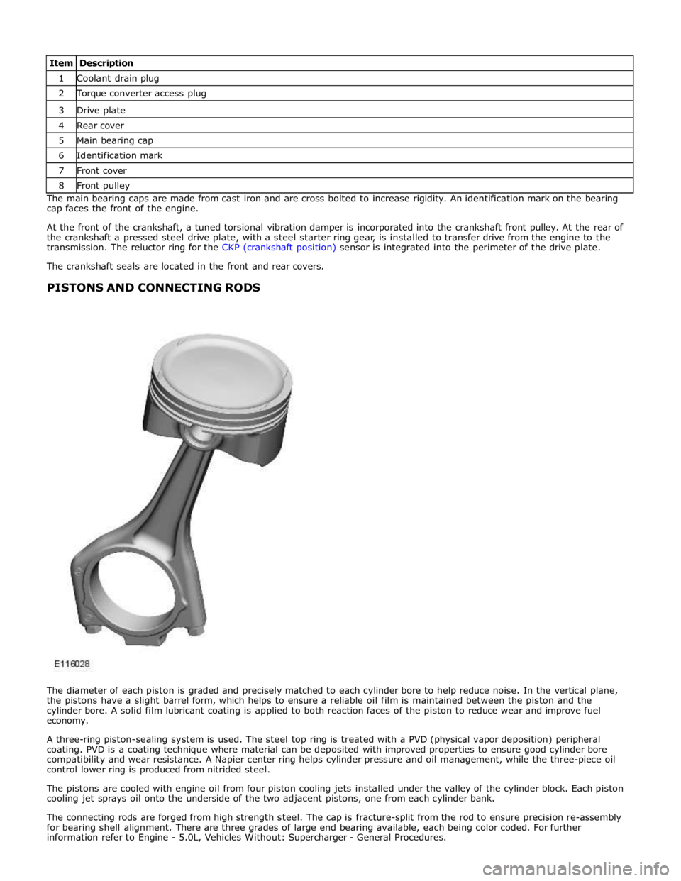
1 Coolant drain plug 2 Torque converter access plug 3 Drive plate 4 Rear cover 5 Main bearing cap 6 Identification mark 7 Front cover 8 Front pulley The main bearing caps are made from cast iron and are cross bolted to increase rigidity. An identification mark on the bearing
cap faces the front of the engine.
At the front of the crankshaft, a tuned torsional vibration damper is incorporated into the crankshaft front pulley. At the rear of
the crankshaft a pressed steel drive plate, with a steel starter ring gear, is installed to transfer drive from the engine to the
transmission. The reluctor ring for the CKP (crankshaft position) sensor is integrated into the perimeter of the drive plate.
The crankshaft seals are located in the front and rear covers.
PISTONS AND CONNECTING RODS
The diameter of each piston is graded and precisely matched to each cylinder bore to help reduce noise. In the vertical plane,
the pistons have a slight barrel form, which helps to ensure a reliable oil film is maintained between the piston and the
cylinder bore. A solid film lubricant coating is applied to both reaction faces of the piston to reduce wear and improve fuel
economy.
A three-ring piston-sealing system is used. The steel top ring is treated with a PVD (physical vapor deposition) peripheral
coating. PVD is a coating technique where material can be deposited with improved properties to ensure good cylinder bore
compatibility and wear resistance. A Napier center ring helps cylinder pressure and oil management, while the three-piece oil
control lower ring is produced from nitrided steel.
The pistons are cooled with engine oil from four piston cooling jets installed under the valley of the cylinder block. Each piston
cooling jet sprays oil onto the underside of the two adjacent pistons, one from each cylinder bank.
The connecting rods are forged from high strength steel. The cap is fracture-split from the rod to ensure precision re-assembly
for bearing shell alignment. There are three grades of large end bearing available, each being color coded. For further
information refer to Engine - 5.0L, Vehicles Without: Supercharger - General Procedures.
Page 1087 of 3039
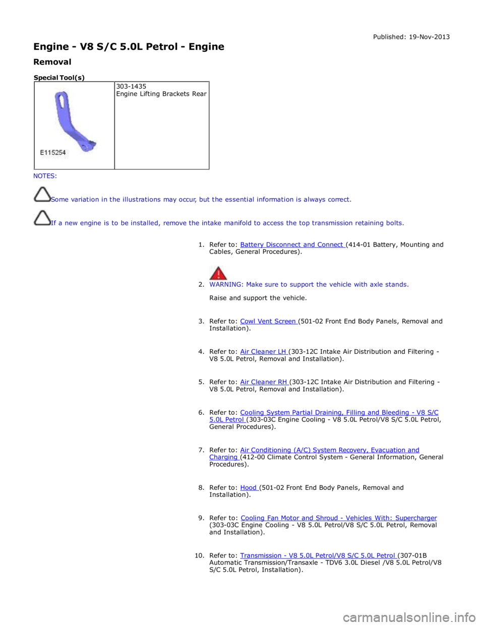
Engine - V8 S/C 5.0L Petrol - Engine
Removal Published: 19-Nov-2013
NOTES:
Some variation in the illustrations may occur, but the essential information is always correct.
If a new engine is to be installed, remove the intake manifold to access the top transmission retaining bolts.
1. Refer to: Battery Disconnect and Connect (414-01 Battery, Mounting and Cables, General Procedures).
2. WARNING: Make sure to support the vehicle with axle stands.
Raise and support the vehicle.
3. Refer to: Cowl Vent Screen (501-02 Front End Body Panels, Removal and Installation).
4. Refer to: Air Cleaner LH (303-12C Intake Air Distribution and Filtering - V8 5.0L Petrol, Removal and Installation).
5. Refer to: Air Cleaner RH (303-12C Intake Air Distribution and Filtering - V8 5.0L Petrol, Removal and Installation).
6. Refer to: Cooling System Partial Draining, Filling and Bleeding - V8 S/C 5.0L Petrol (303-03C Engine Cooling - V8 5.0L Petrol/V8 S/C 5.0L Petrol, General Procedures).
7. Refer to: Air Conditioning (A/C) System Recovery, Evacuation and Charging (412-00 Climate Control System - General Information, General Procedures).
8. Refer to: Hood (501-02 Front End Body Panels, Removal and Installation).
9. Refer to: Cooling Fan Motor and Shroud - Vehicles With: Supercharger (303-03C Engine Cooling - V8 5.0L Petrol/V8 S/C 5.0L Petrol, Removal
and Installation).
10. Refer to: Transmission - V8 5.0L Petrol/V8 S/C 5.0L Petrol (307-01B Automatic Transmission/Transaxle - TDV6 3.0L Diesel /V8 5.0L Petrol/V8
S/C 5.0L Petrol, Installation). 303-1435
Engine Lifting Brackets Rear Special Tool(s)
Page 1107 of 3039
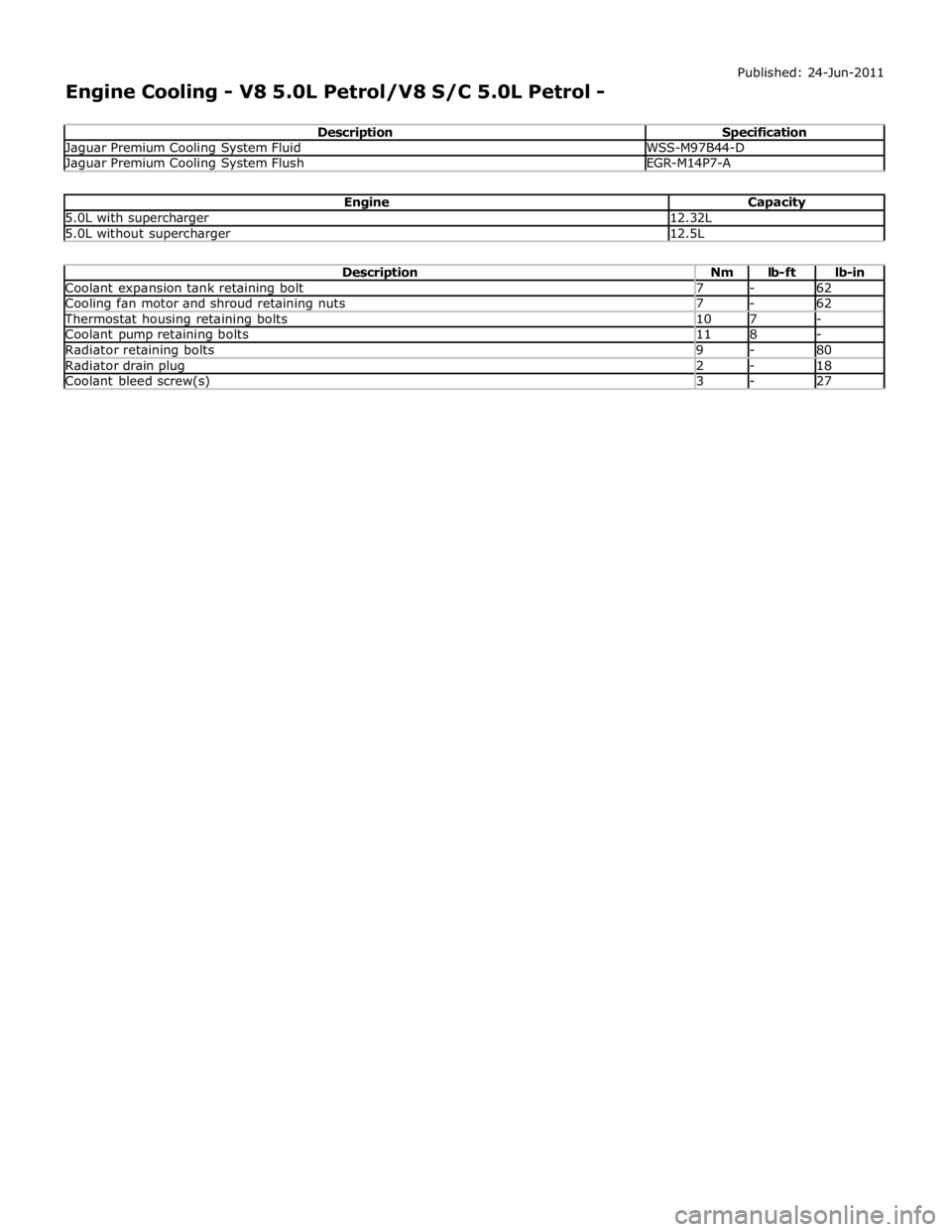
Jaguar Premium Cooling System Fluid WSS-M97B44-D Jaguar Premium Cooling System Flush EGR-M14P7-A
Engine Capacity 5.0L with supercharger 12.32L 5.0L without supercharger 12.5L
Description Nm lb-ft lb-in Coolant expansion tank retaining bolt 7 - 62 Cooling fan motor and shroud retaining nuts 7 - 62 Thermostat housing retaining bolts 10 7 - Coolant pump retaining bolts 11 8 - Radiator retaining bolts 9 - 80 Radiator drain plug 2 - 18 Coolant bleed screw(s) 3 - 27
Page 1408 of 3039
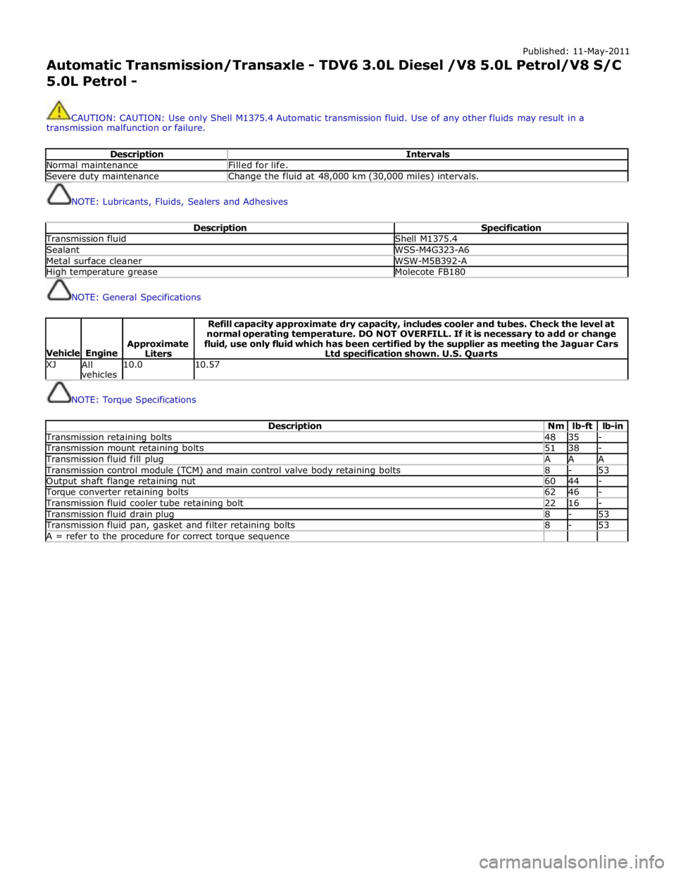
Published: 11-May-2011
Automatic Transmission/Transaxle - TDV6 3.0L Diesel /V8 5.0L Petrol/V8 S/C 5.0L Petrol -
CAUTION: CAUTION: Use only Shell M1375.4 Automatic transmission fluid. Use of any other fluids may result in a
transmission malfunction or failure.
Description Intervals Normal maintenance Filled for life. Severe duty maintenance Change the fluid at 48,000 km (30,000 miles) intervals.
NOTE: Lubricants, Fluids, Sealers and Adhesives
Description Specification Transmission fluid Shell M1375.4 Sealant WSS-M4G323-A6 Metal surface cleaner WSW-M5B392-A High temperature grease Molecote FB180
NOTE: General Specifications
Vehicle
Engine
Approximate
Liters Refill capacity approximate dry capacity, includes cooler and tubes. Check the level at
normal operating temperature. DO NOT OVERFILL. If it is necessary to add or change
fluid, use only fluid which has been certified by the supplier as meeting the Jaguar Cars
Ltd specification shown. U.S. Quarts XJ
All
vehicles 10.0 10.57
NOTE: Torque Specifications
Description Nm lb-ft lb-in Transmission retaining bolts 48 35 - Transmission mount retaining bolts 51 38 - Transmission fluid fill plug A A A Transmission control module (TCM) and main control valve body retaining bolts 8 - 53 Output shaft flange retaining nut 60 44 - Torque converter retaining bolts 62 46 - Transmission fluid cooler tube retaining bolt 22 16 - Transmission fluid drain plug 8 - 53 Transmission fluid pan, gasket and filter retaining bolts 8 - 53 A = refer to the procedure for correct torque sequence