2010 JAGUAR XFR high beam
[x] Cancel search: high beamPage 2037 of 3039

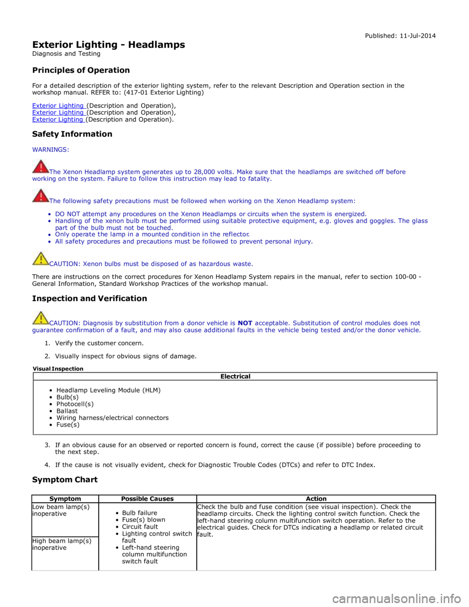
Exterior Lighting - Headlamps
Diagnosis and Testing
Principles of Operation Published: 11-Jul-2014
For a detailed description of the exterior lighting system, refer to the relevant Description and Operation section in the
workshop manual. REFER to: (417-01 Exterior Lighting)
Exterior Lighting (Description and Operation), Exterior Lighting (Description and Operation), Exterior Lighting (Description and Operation).
Safety Information
WARNINGS:
The Xenon Headlamp system generates up to 28,000 volts. Make sure that the headlamps are switched off before
working on the system. Failure to follow this instruction may lead to fatality.
The following safety precautions must be followed when working on the Xenon Headlamp system:
DO NOT attempt any procedures on the Xenon Headlamps or circuits when the system is energized.
Handling of the xenon bulb must be performed using suitable protective equipment, e.g. gloves and goggles. The glass
part of the bulb must not be touched.
Only operate the lamp in a mounted condition in the reflector.
All safety procedures and precautions must be followed to prevent personal injury.
CAUTION: Xenon bulbs must be disposed of as hazardous waste.
There are instructions on the correct procedures for Xenon Headlamp System repairs in the manual, refer to section 100-00 -
General Information, Standard Workshop Practices of the workshop manual.
Inspection and Verification
CAUTION: Diagnosis by substitution from a donor vehicle is NOT acceptable. Substitution of control modules does not
guarantee confirmation of a fault, and may also cause additional faults in the vehicle being tested and/or the donor vehicle.
1. Verify the customer concern.
2. Visually inspect for obvious signs of damage.
3. If an obvious cause for an observed or reported concern is found, correct the cause (if possible) before proceeding to
the next step.
4. If the cause is not visually evident, check for Diagnostic Trouble Codes (DTCs) and refer to DTC Index.
Symptom Chart
Symptom Possible Causes Action Low beam lamp(s)
inoperative
Bulb failure
Fuse(s) blown
Circuit fault
Lighting control switch
fault
Left-hand steering
column multifunction
switch fault Check the bulb and fuse condition (see visual inspection). Check the
headlamp circuits. Check the lighting control switch function. Check the
left-hand steering column multifunction switch operation. Refer to the
electrical guides. Check for DTCs indicating a headlamp or related circuit
fault. High beam lamp(s)
inoperative Electrical
Headlamp Leveling Module (HLM)
Bulb(s)
Photocell(s)
Ballast
Wiring harness/electrical connectors
Fuse(s) Visual Inspection
Page 2038 of 3039

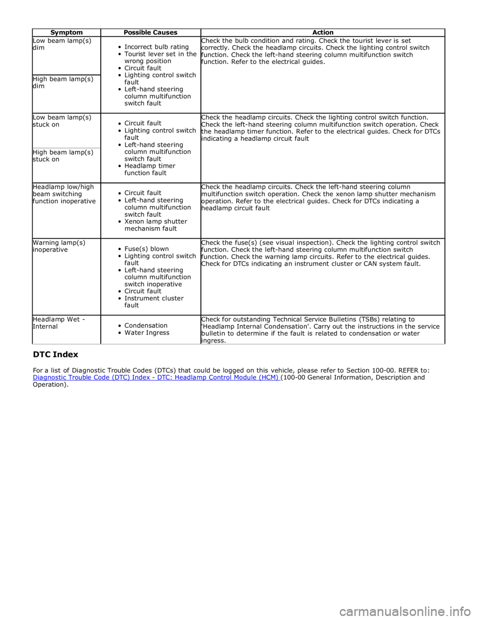
Symptom Possible Causes Action Low beam lamp(s)
dim
Incorrect bulb rating
Tourist lever set in the
wrong position
Circuit fault
Lighting control switch
fault
Left-hand steering
column multifunction
switch fault Check the bulb condition and rating. Check the tourist lever is set
correctly. Check the headlamp circuits. Check the lighting control switch
function. Check the left-hand steering column multifunction switch
function. Refer to the electrical guides. High beam lamp(s)
dim Low beam lamp(s)
stuck on
Circuit fault
Lighting control switch
fault
Left-hand steering
column multifunction
switch fault
Headlamp timer
function fault Check the headlamp circuits. Check the lighting control switch function.
Check the left-hand steering column multifunction switch operation. Check
the headlamp timer function. Refer to the electrical guides. Check for DTCs
indicating a headlamp circuit fault High beam lamp(s)
stuck on Headlamp low/high
beam switching
function inoperative
Circuit fault
Left-hand steering
column multifunction
switch fault
Xenon lamp shutter
mechanism fault Check the headlamp circuits. Check the left-hand steering column
multifunction switch operation. Check the xenon lamp shutter mechanism
operation. Refer to the electrical guides. Check for DTCs indicating a
headlamp circuit fault Warning lamp(s)
inoperative
Fuse(s) blown
Lighting control switch
fault
Left-hand steering
column multifunction
switch inoperative
Circuit fault
Instrument cluster
fault Check the fuse(s) (see visual inspection). Check the lighting control switch
function. Check the left-hand steering column multifunction switch
function. Check the warning lamp circuits. Refer to the electrical guides.
Check for DTCs indicating an instrument cluster or CAN system fault. Headlamp Wet -
Internal
Condensation
Water Ingress Check for outstanding Technical Service Bulletins (TSBs) relating to
'Headlamp Internal Condensation'. Carry out the instructions in the service
bulletin to determine if the fault is related to condensation or water ingress. DTC Index
For a list of Diagnostic Trouble Codes (DTCs) that could be logged on this vehicle, please refer to Section 100-00. REFER to:
Diagnostic Trouble Code (DTC) Index - DTC: Headlamp Control Module (HCM) (100-00 General Information, Description and Operation).
Page 2066 of 3039

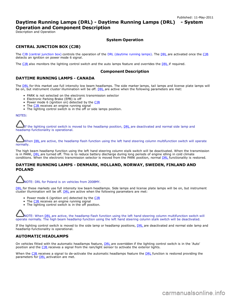
Published: 11-May-2011
Daytime Running Lamps (DRL) - Daytime Running Lamps (DRL) - System
Operation and Component Description
Description and Operation
CENTRAL JUNCTION BOX (CJB) System Operation
The CJB (central junction box) controls the operation of the DRL (daytime running lamps). The DRL are activated once the CJB detects an ignition on power mode 6 signal.
The CJB also monitors the lighting control switch and the auto lamps feature and overrides the DRL if required.
DAYTIME RUNNING LAMPS - CANADA Component Description
The DRL for this market use full intensity low beam headlamps. The side marker lamps, tail lamps and license plate lamps will be on, but instrument cluster illumination will be off. DRL are active when the following parameters are met:
PARK is not selected on the electronic transmission selector
Electronic Parking Brake (EPB) is off
Power mode 6 (ignition on) detected by the CJB The CJB receives an engine running signal The lighting control switch is in the off or side lamps position.
NOTES:
If the lighting control switch is moved to the headlamp position, DRL are deactivated and normal side lamp and headlamp functionality is operational.
When DRL are active, the headlamp flash function using the left hand steering column multifunction switch will operate normally.
The high beam headlamp function using the left hand steering column stalk switch will be deactivated. When the transmission
is in PARK, DRL are turned off. This is to reduce battery discharge during long periods of engine idling in cold climate conditions. When the electronic transmission selector is moved from the PARK position, normal DRL functionality is restored.
DAYTIME RUNNING LAMPS - DENMARK, HOLLAND, NORWAY, SWEDEN, FINLAND AND POLAND
NOTE: DRL for Poland is on vehicles from 2008MY.
DRL for these markets use full intensity low beam headlamps. Side lamps and license plate lamps will be on, but instrument cluster illumination will be off. DRL are active when the following parameters are met:
Power mode 6 (ignition on) detected by the CJB The CJB receives an engine running signal The lighting control switch is in the off position.
NOTE: When DRL are active, the headlamp flash function using the left hand steering column multifunction switch will operate normally. The high beam headlamp function using the left hand steering column stalk switch will be deactivated.
If the lighting control switch is moved to the side lamp or headlamp positions, DRL are deactivated and normal side lamp and headlamp functionality is operational.
AUTOMATIC HEADLAMPS
On vehicles fitted with the automatic headlamps feature, DRL are overridden if the lighting control switch is in the 'Auto' position and the CJB receives a signal from the rain/light sensor to activate the exterior lights.
When the CJB receives a signal to de-activate the automatic headlamps feature the DRL function is restored providing the parameters for DRL activation are met.
Page 2090 of 3039

DTC Description Possible Cause Action B1C7913 Front Washer Pump
Screenwash pump control
circuit - open circuit Carry out any pinpoint tests associated with this DTC
using the manufacturer approved diagnostic system.
Refer to the electrical circuit diagrams and check
screenwash pump control circuit for open circuit B1C9812
Left Corner Lamp
Circuit
Left front corner lamp control
circuit - short to power Refer to the electrical circuit diagrams and check left
front corner lamp control circuit for short to power B1C9814
Left Corner Lamp
Circuit
Left front corner lamp control
circuit - short to ground, open
circuit Refer to the electrical circuit diagrams and check left
front corner lamp control circuit for short to ground, open
circuit B1C9912
Right Corner Lamp
Circuit
Right front corner lamp control
circuit - short to power Refer to the electrical circuit diagrams and check right
front corner lamp control circuit for short to power B1C9914
Right Corner Lamp
Circuit
Right front corner lamp control
circuit - short to ground, open
circuit Refer to the electrical circuit diagrams and check right
front corner lamp control circuit for short to ground, open
circuit B1D0011 Left Low Beam
Left dip beam control circuit -
short to ground Carry out any pinpoint tests associated with this DTC
using the manufacturer approved diagnostic system.
Refer to the electrical circuit diagrams and check left dip
beam control circuit for short to ground B1D0012 Left Low Beam
Left dip beam control circuit -
short to power Refer to the electrical circuit diagrams and check left dip
beam control circuit for short to power B1D0013 Left Low Beam
Left dip beam control circuit -
open circuit Refer to the electrical circuit diagrams and check left dip
beam control circuit for open circuit B1D0111 Right Low Beam
Right dip beam control circuit -
short to ground Carry out any pinpoint tests associated with this DTC
using the manufacturer approved diagnostic system.
Refer to the electrical circuit diagrams and check right dip
beam control circuit for short to ground B1D0112 Right Low Beam
Right dip beam control circuit -
short to power Refer to the electrical circuit diagrams and check right dip
beam control circuit for short to power B1D0113 Right Low Beam
Right dip beam control circuit -
open circuit Refer to the electrical circuit diagrams and check right dip
beam control circuit for open circuit B1D0211
Left High Beam
Circuit
Left high beam control circuit -
short to ground Refer to the electrical circuit diagrams and check left high
beam control circuit for short to ground B1D0212
Left High Beam
Circuit
Left high beam control circuit -
short to power Refer to the electrical circuit diagrams and check left high
beam control circuit for short to power B1D0213
Left High Beam
Circuit
Left high beam control circuit -
open circuit Refer to the electrical circuit diagrams and check left high
beam control circuit for open circuit B1D0311
Right High Beam
Circuit
Right high beam control circuit
- short to ground Refer to the electrical circuit diagrams and check right
high beam control circuit for short to ground B1D0312
Right High Beam
Circuit
Right high beam control circuit
- short to power Refer to the electrical circuit diagrams and check right
high beam control circuit for short to power B1D0313
Right High Beam
Circuit
Right high beam control circuit
- open circuit Refer to the electrical circuit diagrams and check right
high beam control circuit for open circuit B1D1711
Battery Backed
Sounder
Battery backed sounder
inclination sensor control circuit
- short to ground Refer to the electrical circuit diagrams and check battery
backed sounder inclination sensor control circuit for short
to ground B1D1811 Volumetric Sensor
Intrusion sensor module supply
circuit - short to ground Carry out any pinpoint tests associated with this DTC
using the manufacturer approved diagnostic system.
Refer to the electrical circuit diagrams and check
intrusion sensor module supply circuit for short to ground www.JagDocs.com