2010 JAGUAR XFR tailgate
[x] Cancel search: tailgatePage 1665 of 3039

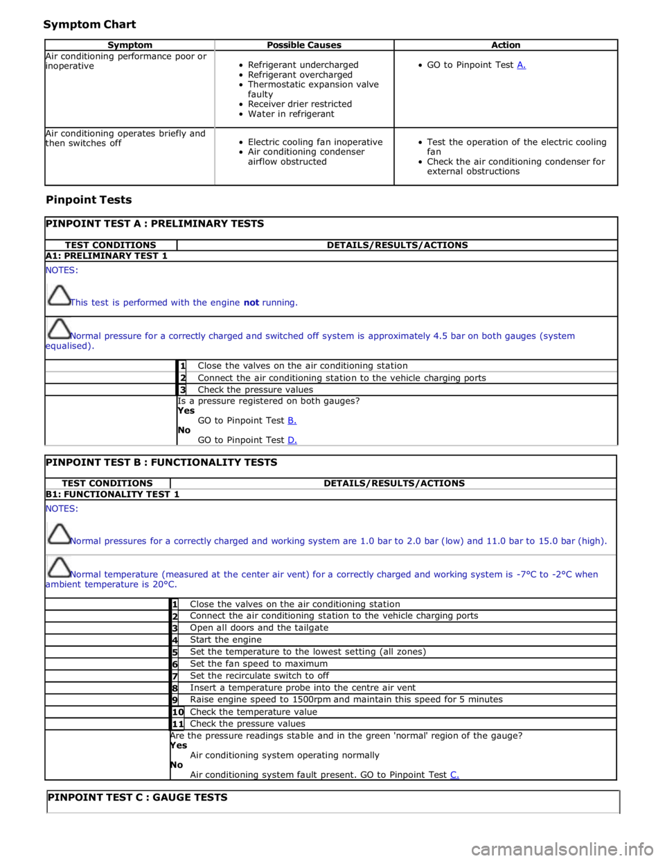
Symptom Chart
Symptom Possible Causes Action Air conditioning performance poor or
inoperative
Refrigerant undercharged
Refrigerant overcharged
Thermostatic expansion valve
faulty
Receiver drier restricted
Water in refrigerant
GO to Pinpoint Test A. Air conditioning operates briefly and
then switches off
Electric cooling fan inoperative
Air conditioning condenser
airflow obstructed
Test the operation of the electric cooling
fan
Check the air conditioning condenser for
external obstructions Pinpoint Tests
PINPOINT TEST A : PRELIMINARY TESTS TEST CONDITIONS DETAILS/RESULTS/ACTIONS A1: PRELIMINARY TEST 1 NOTES:
This test is performed with the engine not running.
Normal pressure for a correctly charged and switched off system is approximately 4.5 bar on both gauges (system
equalised). 1 Close the valves on the air conditioning station 2 Connect the air conditioning station to the vehicle charging ports 3 Check the pressure values Is a pressure registered on both gauges? Yes
GO to Pinpoint Test B. No
GO to Pinpoint Test D.
PINPOINT TEST B : FUNCTIONALITY TESTS TEST CONDITIONS DETAILS/RESULTS/ACTIONS B1: FUNCTIONALITY TEST 1 NOTES:
Normal pressures for a correctly charged and working system are 1.0 bar to 2.0 bar (low) and 11.0 bar to 15.0 bar (high).
Normal temperature (measured at the center air vent) for a correctly charged and working system is -7°C to -2°C when
ambient temperature is 20°C. 1 Close the valves on the air conditioning station 2 Connect the air conditioning station to the vehicle charging ports 3 Open all doors and the tailgate 4 Start the engine 5 Set the temperature to the lowest setting (all zones) 6 Set the fan speed to maximum 7 Set the recirculate switch to off 8 Insert a temperature probe into the centre air vent 9 Raise engine speed to 1500rpm and maintain this speed for 5 minutes 10 Check the temperature value 11 Check the pressure values Are the pressure readings stable and in the green 'normal' region of the gauge? Yes
Air conditioning system operating normally No
Air conditioning system fault present. GO to Pinpoint Test C.
PINPOINT TEST C : GAUGE TESTS
Page 2495 of 3039

Published: 18-Mar-2014
Handles, Locks, Latches and Entry Systems - Locks, Latches and Entry Systems
Diagnosis and Testing
Principle of Operation
For a detailed description of the locks, latches and entry systems and operation, refer to the relevant Description and
Operation section of the workshop manual. REFER to: Handles, Locks, Latches and Entry Systems (501-14, Description and
Operation).
Inspection and Verification
CAUTION: Diagnosis by substitution from a donor vehicle is NOT acceptable. Substitution of control modules does not
guarantee confirmation of a fault and may also cause additional faults in the vehicle being checked and/or the donor vehicle
NOTE: Check and rectify basic faults before beginning diagnostic routines involving pinpoint tests
1. Verify the customer concern, to be sure the correct issue is investigated
2. Visually inspect for obvious signs of damage and system integrity
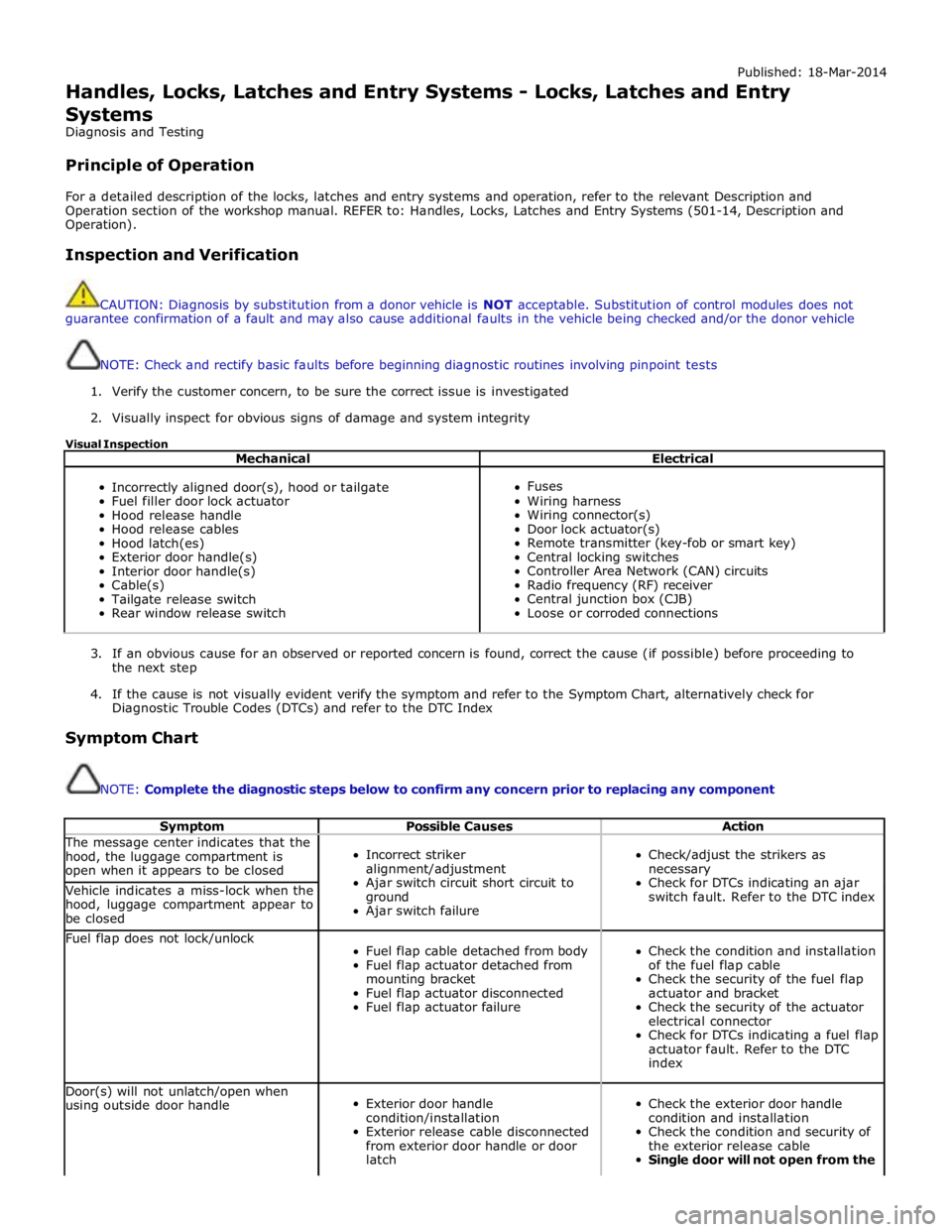
Visual Inspection
Mechanical Electrical
Incorrectly aligned door(s), hood or tailgate
Fuel filler door lock actuator
Hood release handle
Hood release cables
Hood latch(es)
Exterior door handle(s)
Interior door handle(s)
Cable(s)
Tailgate release switch
Rear window release switch
Fuses
Wiring harness
Wiring connector(s)
Door lock actuator(s)
Remote transmitter (key-fob or smart key)
Central locking switches
Controller Area Network (CAN) circuits
Radio frequency (RF) receiver
Central junction box (CJB)
Loose or corroded connections
3. If an obvious cause for an observed or reported concern is found, correct the cause (if possible) before proceeding to
the next step
4. If the cause is not visually evident verify the symptom and refer to the Symptom Chart, alternatively check for
Diagnostic Trouble Codes (DTCs) and refer to the DTC Index
Symptom Chart
NOTE: Complete the diagnostic steps below to confirm any concern prior to replacing any component
Symptom Possible Causes Action The message center indicates that the
hood, the luggage compartment is
open when it appears to be closed
Incorrect striker
alignment/adjustment
Ajar switch circuit short circuit to
ground
Ajar switch failure
Check/adjust the strikers as
necessary
Check for DTCs indicating an ajar
switch fault. Refer to the DTC index Vehicle indicates a miss-lock when the
hood, luggage compartment appear to
be closed Fuel flap does not lock/unlock
Fuel flap cable detached from body
Fuel flap actuator detached from
mounting bracket
Fuel flap actuator disconnected
Fuel flap actuator failure
Check the condition and installation
of the fuel flap cable
Check the security of the fuel flap
actuator and bracket
Check the security of the actuator
electrical connector
Check for DTCs indicating a fuel flap
actuator fault. Refer to the DTC
index Door(s) will not unlatch/open when
using outside door handle
Exterior door handle
condition/installation
Exterior release cable disconnected
from exterior door handle or door
latch
Check the exterior door handle
condition and installation
Check the condition and security of
the exterior release cable
Single door will not open from the
Page 2719 of 3039

Apply polyester filler (only onto bare metal).
Apply filler.
Lightly sand the whole component.
Thoroughly clean with silicone remover and rub dry.
Apply corrosion protection primer to bare areas.
The clinched flanges on the hood, doors, tailgate and liftgate must be sealed with clinched flange sealer, if this is not already
applied.
Weld Components
Use a stripping disc to remove the cathodic primer on the inside and outside of the area to be welded. The stripped area
should be kept as small as possible, retaining as much of the cathodic primer as possible, taking care not to damage the zinc
coating.
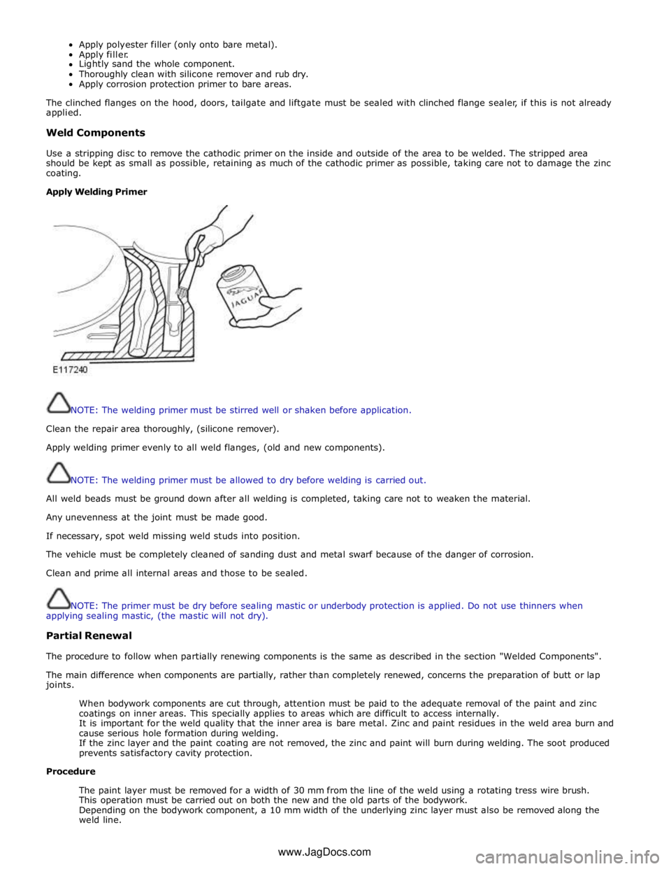
Apply Welding Primer
NOTE: The welding primer must be stirred well or shaken before application.
Clean the repair area thoroughly, (silicone remover).
Apply welding primer evenly to all weld flanges, (old and new components).
NOTE: The welding primer must be allowed to dry before welding is carried out.
All weld beads must be ground down after all welding is completed, taking care not to weaken the material.
Any unevenness at the joint must be made good.
If necessary, spot weld missing weld studs into position.
The vehicle must be completely cleaned of sanding dust and metal swarf because of the danger of corrosion.
Clean and prime all internal areas and those to be sealed.
NOTE: The primer must be dry before sealing mastic or underbody protection is applied. Do not use thinners when
applying sealing mastic, (the mastic will not dry).
Partial Renewal
The procedure to follow when partially renewing components is the same as described in the section "Welded Components".
The main difference when components are partially, rather than completely renewed, concerns the preparation of butt or lap
joints.
When bodywork components are cut through, attention must be paid to the adequate removal of the paint and zinc
coatings on inner areas. This specially applies to areas which are difficult to access internally.
It is important for the weld quality that the inner area is bare metal. Zinc and paint residues in the weld area burn and
cause serious hole formation during welding.
If the zinc layer and the paint coating are not removed, the zinc and paint will burn during welding. The soot produced
prevents satisfactory cavity protection.
Procedure
The paint layer must be removed for a width of 30 mm from the line of the weld using a rotating tress wire brush.
This operation must be carried out on both the new and the old parts of the bodywork.
Depending on the bodywork component, a 10 mm width of the underlying zinc layer must also be removed along the
weld line. www.JagDocs.com
Page 2732 of 3039

Part N-umber
Body Repairs - Water Leaks - Water Leaks
Description and Operation
General Published: 11-May-2011
If water leaks occur after bodywork repairs, the cause can be established using the checks described below. A
systematic and logical procedure is required to locate water leaks. Before beginning extensive checks, a thorough visual
inspection must be carried out.
Visual Inspection
- The following characteristics may indicate existing leaks:
- Check the clearance and accurate fit of ancillary components such as the hood, tailgate, liftgate, doors, and so
on.
- Check for correct fit and possible damage to sealing elements such as blanking plugs, rubber door seals, and so
on.
- Check water drain holes for unhindered flow.
Various tests can be used to provide further information on possible leaks:
- Water test
- Washer test
- Road test
- Chalk (powder) test
Practical execution of tests and checks
Water test
NOTE: Never aim a jet of water directly at a rubber seal.
Carry out the water test with a second person present (in the passenger compartment).
Use variable washer nozzles (concentrated water jet to fine spray mist).
Start in the lower section and spray the whole area, working upwards in stages.
Washer test
Further tests can be carried out in the washer system.
Some leaks originate here, or only occur here.
The relevant passenger compartment should be checked using a torch during the wash procedure.
Road test
If no leaks are located during the tests above, road tests should be carried out on wet roads.
Road tests under various conditions:
- At various speeds.
- On various road surfaces (asphalt to cobbles).
- With loaded or unloaded vehicle.
- Driving through puddles (splash water).
Chalk test (powder test)
In this test, the clamping load and the bearing surface of the seal are checked.
Performing the test:
- Dust the door seal with powder or coat with chalk.
- Coat the bearing surface of the seal with a thin film of Vaseline.
- Slowly close the door and open it again.
- Check the width and continuity of the imprint on the door seal.
Other test equipment
Other equipment such as stethoscopes, UV lamps, special mirrors or ultrasound measuring instruments can be used to
locate leaks.
Rectifying the leak using recommended tools, auxiliary equipment and materials
Tools and auxiliary equipment:
- Dry, absorbent cloths
- Variable washer nozzle
- Torch, fluorescent tube
- Mirror
- Compressed air
- Seal lip installer
- Wet/dry vacuum cleaner
- Sealing compound compressor
- Remover for interior trim
- Cutter blade or pocket knife
- Wedge (wood or plastic)
- Hot air blower
- Special mirror for concealed leaks
Page 2733 of 3039

- Air flow checker
- Sealing compound (tape and plastic compound)
- Multi-purpose sticker
- Clinched flange sealer
- Window sealing compound
- Water shield (PVC)
- Double-sided adhesive tape for water shield
- Methylated spirit (available from trade outlets)
- PU adhesive
- Silicone remover
- Tar remover
Water leaks according to mileage or running time
Increasing mileage has an effect on the problem of leaks in a vehicle. Possible influencing factors are:
Servicing and maintenance of seals:
- No maintenance, lack of maintenance or incorrect maintenance
- Using an incorrect agent
Damaged seals:
- As a result of aging, wear or incorrect handling/assembly.
Heavy soiling of the vehicle:
- Heavy soiling of a vehicle can seriously impair the function of water drainage channels in particular, and also of
rubber seals.
Age-related factors:
- Environmental factors
- UV radiation
- Extreme climatic conditions
Corrosion can have a serious impact on bodywork, in particular as a result of:
- Lightly or heavily rusted seal carriers
- Rusted body seal welds
- Perforation corrosion
Water leaks after body repairs
If a vehicle develops a leak after body repairs, the following points must be taken into consideration in particular:
The correct seating of ancillary components and their seals must be checked.
The correct alignment of doors/tailgate and liftgate must be checked. The associated seals must not be damaged and
must be installed correctly.
Check that panel seams are correctly sealed.
The correct seating of rubber grommets must be checked.
Directly-glazed windows must have correct and complete bonding.
Water drainage system
If a vehicle develops water leaks, then areas into which water is routed or drained should be checked first.
Page 2736 of 3039

NOTE: In the case of a sliding or tilting roof, the external rubber seal and the lock actuator or latch mechanism
must be checked first of all.
- Check the water trap for leaks.
- Check the drain hoses for leaks and for correct connection to the water trap.
- Check the drainage system for unhindered flow, and blow out with compressed air if necessary.
- Check the external seal and the correct adjustment of the sliding roof.
Liftgate
Diagnosis:
- Ingress of water into rear headlining area and luggage area.
Cause:
- The leak problems of the tailgate and liftgate correspond to those of the doors.
- In addition to this, the area to be sealed is much bigger. The routing holes for cables and hoses must also be
sealed.
- The rubber grommets for the routing holes must be checked for damage and correct seating (fully unhooked).
- The mounting points of the liftgate hinges may leak.
Corrective action:
- Check the rubber grommets and renew if necessary.
- Check the hinge mounting points, and re-seal with sealing compound if necessary.
Forced air extraction
Diagnosis:
- Ingress of water into side luggage compartment area
Cause:
- The forced air extraction for the vehicle interior is located in the quarter panel lower extension.
- The rubber flap of the forced air extraction must be able to move freely.
Corrective action:
- Remove the forced air extraction.
- Check the seal area between the bodywork and housing, as well as the rubber flap.
- Renew seal if necessary.
Rear window
Diagnosis:
- Ingress of water into the luggage compartment area
Cause:
- Rear window leaking.
- Check for leak in the same way as for leaking windscreen.