2010 JAGUAR XFR child seat
[x] Cancel search: child seatPage 60 of 3039

Have a suitable fire extinguisher available when using welding or heating equipment.
First Aid
Apart from meeting any legal requirements it is desirable for someone in the workshop to be trained in First Aid procedures.
Splashes in the eye should be flushed carefully with clean water for at least ten minutes.
Soiled skin should be washed with soap and water.
Individuals affected by inhalation of gases, fumes etc. should be removed to fresh air immediately. If effects persist, consult a
doctor.
If liquids are swallowed inadvertently, consult a doctor giving the information on the container or label. Do not induce vomiting
unless this action is indicated on the label.
Fluoroelastomer
See Viton.
Foams - Polyurethane
See also Fire.
Used in sound and noise insulation. Cured foams used in seat and trim cushioning.
Follow manufacturer's instructions.
Unreacted components are irritating and may be harmful to the skin and eyes. Wear gloves and goggles.
Individuals with chronic respiratory diseases, asthma, bronchial medical problems, or histories of allergic diseases should not
work in or near uncured materials.
The components, vapors or spray mists can cause direct irritation, sensitivity reactions and may be toxic or harmful.
Vapors and spray mists must not be inhaled. These materials must be applied with adequate ventilation and respiratory
protection. Do not remove the respirator immediately after spraying, wait until the vapor/mists have cleared.
Burning of the uncured components and the cured foams can generate toxic and harmful fumes. Smoking, naked flames or the
use of electrical equipment during foaming operations and until vapors/mists have cleared should not be allowed. Any heat
cutting of cured foams or partially cured foams should be conducted with extraction ventilation.
Freon
See Air Conditioning Refrigerant.
Fuels
See also, Fire, Legal Aspects, Chemicals and Solvents.
Avoid skin contact with fuel where possible. Should contact occur, wash the affected skin with soap and water.
Gasoline (Petrol)
Highly flammable - observe No Smoking policy.
Swallowing can result in mouth and throat irritation and absorption from the stomach can result in drowsiness and
unconsciousness. Small amounts can be fatal to children. Aspiration of liquid into the lungs e.g. through vomiting, is a very
serious hazard.
Gasoline dries the skin and can cause irritation and dermatitis on prolonged or repeated contact. Liquid in the eye causes
severe pain.
Motor gasoline may contain appreciable quantities of benzene, which is toxic upon inhalation, and the concentration of
gasoline vapors must be kept very low. High concentrations will cause eye, nose and throat irritation, nausea, headache,
depression and symptoms of drunkenness. Very high concentrations will result in rapid loss of consciousness.
Ensure there is adequate ventilation when handling and using gasoline. Great care must be taken to avoid the serious
consequences of inhalation in the event of vapor build up arising from spillages in confined spaces.
Special precautions apply to cleaning and maintenance operations on gasoline storage tanks.
Gasoline should not be used as a cleaning agent. It must not be siphoned by mouth. See First Aid.
Gas - oil (Diesel Fuel)
See warnings and cautions in relevant manual sections.
Combustible.
www.JagDocs.com
Page 66 of 3039

4. Components or assemblies displaying this symbol give warning that the component contains a corrosive substance. See
Acids and Alkalis in this subsection.
5. Vehicles displaying the caution circle with a deleted lighted match symbol, caution against the use of naked lights or
flames within the immediate vicinity due to the presence of highly flammable or explosive liquids or vapors. See Fire in
this subsection.
6. All vehicles with the passenger air bag installed from the factory have a warning sticker attached to the instrument
panel, prohibiting the use of rear facing child seats in the front seating position. Failure to follow this instruction may
result in personal injury.
White Spirit
See Solvents.
Safety Precautions
WARNINGS:
Working on the fuel system results in fuel and fuel vapor being present in the atmosphere. Fuel vapor is extremely
flammable, hence great care must be taken whilst working on the fuel system. Adhere strictly to the following precautions:
Do not smoke in the work area
Display 'no smoking' signs around the area
Disconnect the battery before working on the fuel system
Do not connect/disconnect electrical circuits, use electrical equipment or other tools or engage in working practices
which in any way may result in the production of sparks
Ensure that a CO² fire extinguisher is close at hand
Ensure that dry sand is available to soak up any fuel spillage
Empty fuel using suitable fire proof equipment into an authorized explosion proof container
Page 73 of 3039

Supplementary Restraint System (SRS) Precautions
WARNING: Do not install rear facing child seats in the front passenger seat.
The SRS contains components which are potentially hazardous to service personnel if not handled correctly. The following
guidelines and precautions are intended to alert personnel to potential sources of danger and emphasise the importance of
ensuring the integrity of the SRS components installed to the vehicle.
WARNING: The following precautions MUST be adhered to when working on the SRS system:
The correct procedures must always be used when working on SRS components.
Persons working on the SRS system must be fully trained and have been issued with the safety guidelines.
The airbag modules contain extremely flammable and hazardous compounds. Contact with water, acids or heavy
metals may produce harmful or explosive results. Do not dismantle, incinerate or bring into contact with electricity
before the unit has been deployed.
Always replace a seat belt assembly that has withstood the strain of a severe vehicle impact or if the webbing
shows signs of fraying.
Always disconnect the vehicle battery before carrying out any electric welding on a vehicle installed with an SRS
system.
CAUTION: Do not expose airbag modules or seat belt pre-tensioners to temperatures exceeding 85° C (185° F).
It should be noted that these precautions are not restricted to operations performed when servicing the SRS system. The same
care should be exercised when working on ancillary systems and components located in the vicinity of SRS components; these
include but are not limited to:
Steering wheel airbag, rotary coupler.
Passenger front airbag.
Head airbag modules - front and rear.
Seat belt pre-tensioners.
SRS harnesses, link leads and connectors.
Side (thorax) air bags.
Making the system safe
Before working on or in the vicinity of SRS components, make sure the system is rendered safe by performing the following
operations:
Remove the ignition key.
Disconnect battery, earth lead first.
Wait 2 minutes for the SRS power circuit to discharge before commencing work.
NOTE: The SRS uses energy reserve capacitors to keep the system active in the event of electrical supply failure under
crash conditions. It is necessary to allow the capacitors sufficient time to discharge (2 minutes) in order to avoid the risk of
accidental deployment.
Installation
In order to make sure system integrity, it is essential that the SRS system is regularly checked and maintained so that it is
ready for effective operation in the event of a collision. Carefully inspect SRS components before installation. Do not install a
part that shows signs of being dropped or improperly handled, such as dents, cracks or deformation.
WARNING: The integrity of the SRS systems is critical for safety reasons. Make sure the following precautions are always
adhered to:
Do not install accessories or other objects to trim panels which cover ITS airbags.
Never install used SRS components from another vehicle or attempt to repair an SRS component.
When repairing an SRS system, only use genuine new parts.
Never apply electrical power to an SRS component unless instructed to do so as part of an approved test
procedure.
Special fixings are necessary for installing an airbag module – do not use other fixings and make sure that all
fixings are tightened to the correct torque.
Always use new fixings when replacing an SRS component.
CAUTIONS:
Take care not to trap airbag modules when installing interior trim components.
Make sure SRS components are not contaminated by oil or grease.
NOTES:
Following seat belt pre-tensioner deployment, the seat belts can still be used as conventional seat belts but will need to
Page 102 of 3039

Live air bag modules must be placed in a suitable cage when removed from the vehicle. The air bag or trim cover must be
facing upwards.
Do not install a rearward facing child safety seat to the passenger seat with an activated passenger air bag.
CAUTIONS:
Pyrotechnic components must not be subjected to temperatures higher than 110°C.
Never install aftermarket accessories to the vehicle on or adjacent to the supplemental restraint system module.
Page 2317 of 3039

memory positions to be stored and 'set' button with integral LED (light emitting diode). The seat, door mirror and steering
column motors have position sensors which provide feedback to driver's seat module.
Once the driver's seat, steering column and exterior mirrors have been adjusted, the vehicle is able to memorize these
settings for future use by using the following procedure:
Push the memory 'SET' button, the LED in the switch will illuminate Press the memory button 1 or 2 to memorize the current settings. The LED will extinguish, and a chime will sound to confirm that the settings have been memorized. If the ignition is on, power mode 6, the message center will display a
confirmation message.
The positions can be recalled by pressing the applicable button 1 or 2.
Stall Detection
Seat, steering column and mirror motors are deemed to have stalled if there is no change in the inputs that are received from
the corresponding feedback sensors for 200 ms (seat).
If a stall condition is detected then the drive to that motor is cancelled for the remainder of that memory operation (memory
recall) or until the switch is re-selected (manual movement).
If the motor movement has stopped due to loss of sensor feedback, either stall or sensor failure, then that motor may be
activated again, to move past the stall position, by re-selecting the appropriate switch and pressing for longer than 2 seconds.
This allows control of the motor to be maintained if sensor feedback is lost.
Upon re-selection of movement, if sensor pulses are detected then the motor will continue to be driven until the switch is
released or another stall condition is detected. If sensor feedback is not detected then the motor is only driven for 0.5 second
and then stops until the switch is released and then pressed again, when a further 0.5 second of activation is permitted, and
so on, this is known as inch mode.
For all seat motor manual movements, whenever a motor is driven and a stall occurs, the memory control module records the
position at which the stall occurred. If movement occurs beyond a stall position, then that position is erased from the control
modules memory. This will always allow movement past a previously recorded stall position once movement has been
registered beyond that position. This is the case for both manual and memory movement.
Initialization
When a replacement driver's seat module is fitted, it should be calibrated a Jaguar approved diagnostic system so that the
module can learn the seats absolute position.
Battery Monitor
If the battery voltage drops below 10.5 Volts, then the driver's seat module ignores all requests for a memory recall until the
battery voltage has reached 11.5 Volts. This will conserve as much power in the vehicle battery as possible to enable engine
cranking.
REAR SEATS - DESCRIPTION
The rear seat features a single piece cushion and a 60/40 split squab. Two latches are secured to the rear bulkhead by a pair
of M8 bolts to retain the seat squabs in the upright position. The latches can be released to fold down the individual cushions
by pulling a cable release located below the rear window parcel shelf in the luggage compartment.
ISOFIX fastening points are attached to the vehicle floor to provide secure fastening for compatible child seats.
A centrally mounted center arm rest can be folded down from the 60% squab. The arm rest contains two drinks holders.
Page 2591 of 3039

Safety Belt System - Safety Belt System - Component Location
Description and Operation
NOTE: Authoring Template Published: 11-May-2011
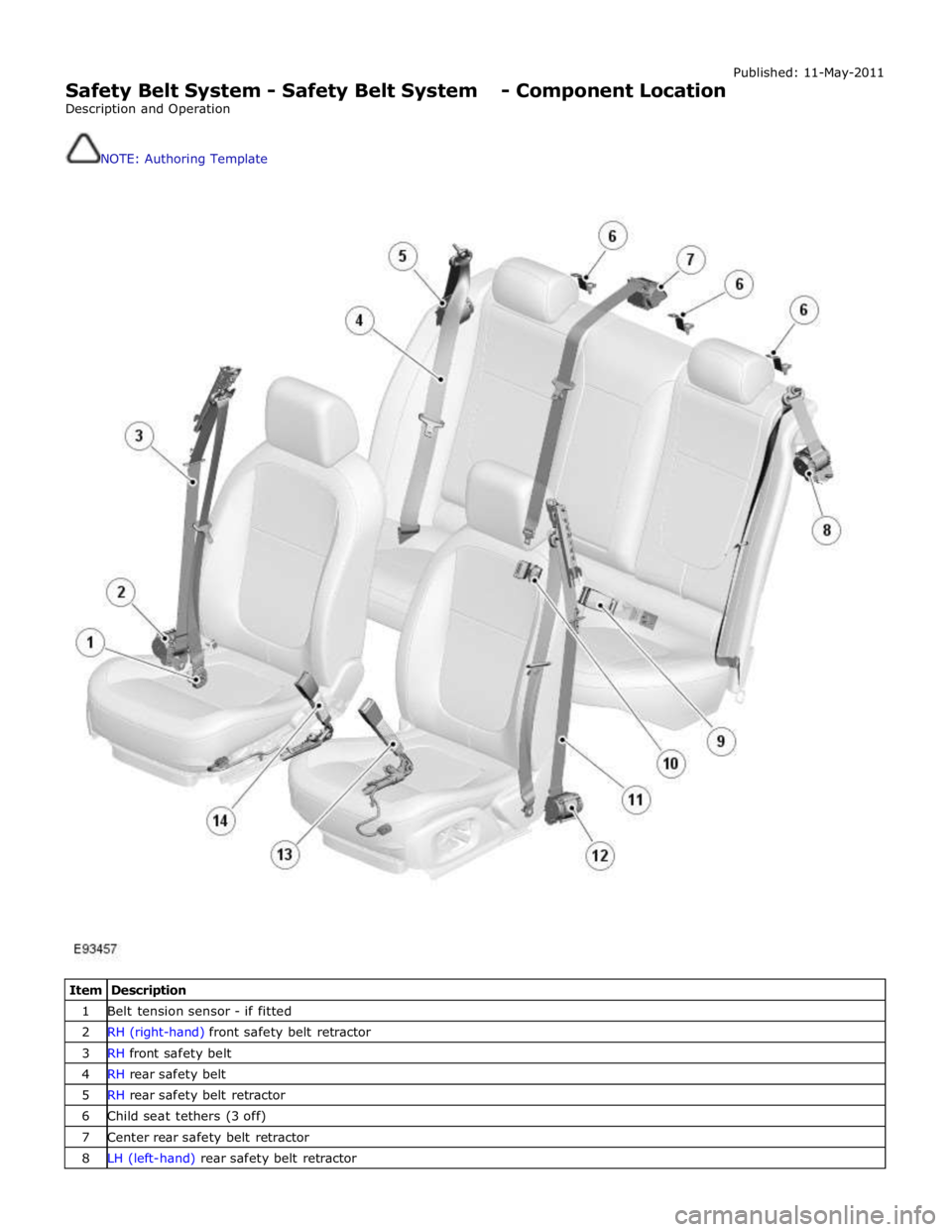
Item Description 1 Belt tension sensor - if fitted 2 RH (right-hand) front safety belt retractor 3 RH front safety belt 4 RH rear safety belt 5 RH rear safety belt retractor 6 Child seat tethers (3 off) 7 Center rear safety belt retractor 8 LH (left-hand) rear safety belt retractor
Page 2593 of 3039

Safety Belt System - Safety Belt System - Overview
Description and Operation
Authoring Template
OVERVIEW Published: 11-May-2011
A three point safety belt is fitted to all seating positions. Each safety belt retractor incorporates an emergency locking feature.
The emergency locking retractor incorporates 2 mechanical inertia devices. One inertia device activates if the safety belt is
subjected to a sharp pull. The second inertia device activates if the vehicle is subject to a sudden deceleration or is on a
severe incline.
North American Specification (NAS) safety belt retractors also include an automatic locking feature. The Automatic Locking
Retractor (ALR) is fitted to all passenger seating positions and allows the safety belt to be tensioned to aid the safe fitment
of child or booster seats. For additional information, refer to the Owners Handbook.
NAS vehicles are also fitted with a belt tension sensor on the front passenger seat. The belt tension sensor is incorporated
into the seat belt lower anchorage and is attached to the seat frame by an M10 Torx head bolt. The belt tension sensor forms
part of the SRS (supplemental restraint system) occupancy detection and classification feature.
The center rear safety belt features a mini-buckle lower anchorage. The mini-buckle is disengaged by inserting a suitable tool
into the small aperture on the front face of the housing.
To aid the fitment of child seats, 3 tethers are located on the rear parcel shelf. Each tether is attached to the parcel shelf with
an M10 Torx head bolt.
A safety belt warning indicator is located in the instrument cluster to remind front seat passengers to fasten their safety belts.
The warning indicator will illuminate if the safety belt of an occupied front seat is not fastened.
Refer to: Instrument Cluster (413-01, Description and Operation).
Page 2597 of 3039

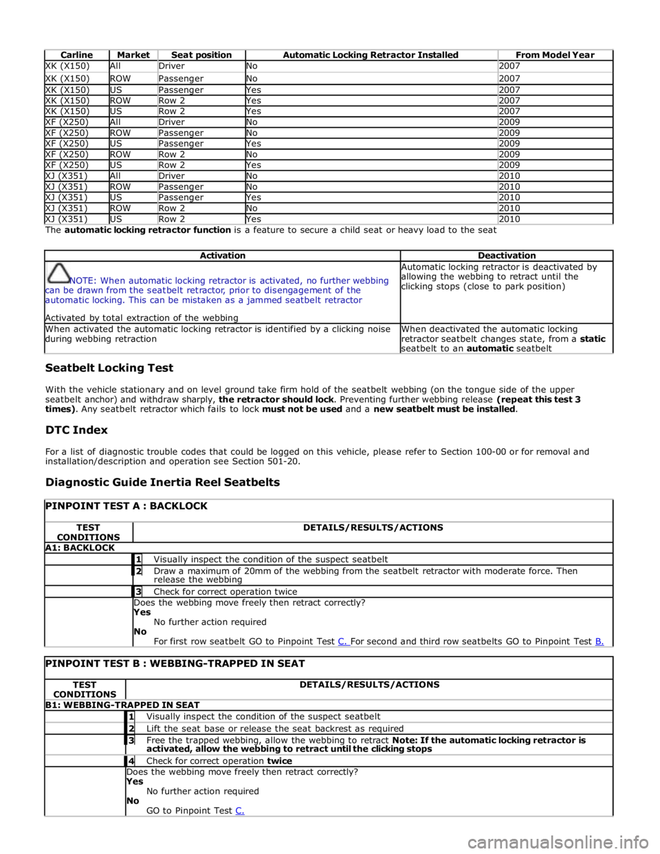
Carline Market Seat position Automatic Locking Retractor Installed From Model Year XK (X150) All Driver No 2007 XK (X150) ROW Passenger No 2007 XK (X150) US Passenger Yes 2007 XK (X150) ROW Row 2 Yes 2007 XK (X150) US Row 2 Yes 2007 XF (X250) All Driver No 2009 XF (X250) ROW Passenger No 2009 XF (X250) US Passenger Yes 2009 XF (X250) ROW Row 2 No 2009 XF (X250) US Row 2 Yes 2009 XJ (X351) All Driver No 2010 XJ (X351) ROW Passenger No 2010 XJ (X351) US Passenger Yes 2010 XJ (X351) ROW Row 2 No 2010 XJ (X351) US Row 2 Yes 2010 The automatic locking retractor function is a feature to secure a child seat or heavy load to the seat
Activation Deactivation
NOTE: When automatic locking retractor is activated, no further webbing
can be drawn from the seatbelt retractor, prior to disengagement of the
automatic locking. This can be mistaken as a jammed seatbelt retractor
Activated by total extraction of the webbing Automatic locking retractor is deactivated by
allowing the webbing to retract until the
clicking stops (close to park position) When activated the automatic locking retractor is identified by a clicking noise
during webbing retraction When deactivated the automatic locking
retractor seatbelt changes state, from a static
seatbelt to an automatic seatbelt Seatbelt Locking Test
With the vehicle stationary and on level ground take firm hold of the seatbelt webbing (on the tongue side of the upper
seatbelt anchor) and withdraw sharply, the retractor should lock. Preventing further webbing release (repeat this test 3
times). Any seatbelt retractor which fails to lock must not be used and a new seatbelt must be installed.
DTC Index
For a list of diagnostic trouble codes that could be logged on this vehicle, please refer to Section 100-00 or for removal and
installation/description and operation see Section 501-20.
Diagnostic Guide Inertia Reel Seatbelts
PINPOINT TEST A : BACKLOCK TEST
CONDITIONS DETAILS/RESULTS/ACTIONS A1: BACKLOCK 1 Visually inspect the condition of the suspect seatbelt 2 Draw a maximum of 20mm of the webbing from the seatbelt retractor with moderate force. Then release the webbing 3 Check for correct operation twice Does the webbing move freely then retract correctly?
Yes
No further action required
No
For first row seatbelt GO to Pinpoint Test C. For second and third row seatbelts GO to Pinpoint Test B.
PINPOINT TEST B : WEBBING-TRAPPED IN SEAT TEST
CONDITIONS DETAILS/RESULTS/ACTIONS B1: WEBBING-TRAPPED IN SEAT 1 Visually inspect the condition of the suspect seatbelt 2 Lift the seat base or release the seat backrest as required 3 Free the trapped webbing, allow the webbing to retract Note: If the automatic locking retractor is activated, allow the webbing to retract until the clicking stops 4 Check for correct operation twice Does the webbing move freely then retract correctly?
Yes
No further action required
No
GO to Pinpoint Test C.