2010 JAGUAR XFR oil amount
[x] Cancel search: oil amountPage 60 of 3039

Have a suitable fire extinguisher available when using welding or heating equipment.
First Aid
Apart from meeting any legal requirements it is desirable for someone in the workshop to be trained in First Aid procedures.
Splashes in the eye should be flushed carefully with clean water for at least ten minutes.
Soiled skin should be washed with soap and water.
Individuals affected by inhalation of gases, fumes etc. should be removed to fresh air immediately. If effects persist, consult a
doctor.
If liquids are swallowed inadvertently, consult a doctor giving the information on the container or label. Do not induce vomiting
unless this action is indicated on the label.
Fluoroelastomer
See Viton.
Foams - Polyurethane
See also Fire.
Used in sound and noise insulation. Cured foams used in seat and trim cushioning.
Follow manufacturer's instructions.
Unreacted components are irritating and may be harmful to the skin and eyes. Wear gloves and goggles.
Individuals with chronic respiratory diseases, asthma, bronchial medical problems, or histories of allergic diseases should not
work in or near uncured materials.
The components, vapors or spray mists can cause direct irritation, sensitivity reactions and may be toxic or harmful.
Vapors and spray mists must not be inhaled. These materials must be applied with adequate ventilation and respiratory
protection. Do not remove the respirator immediately after spraying, wait until the vapor/mists have cleared.
Burning of the uncured components and the cured foams can generate toxic and harmful fumes. Smoking, naked flames or the
use of electrical equipment during foaming operations and until vapors/mists have cleared should not be allowed. Any heat
cutting of cured foams or partially cured foams should be conducted with extraction ventilation.
Freon
See Air Conditioning Refrigerant.
Fuels
See also, Fire, Legal Aspects, Chemicals and Solvents.
Avoid skin contact with fuel where possible. Should contact occur, wash the affected skin with soap and water.
Gasoline (Petrol)
Highly flammable - observe No Smoking policy.
Swallowing can result in mouth and throat irritation and absorption from the stomach can result in drowsiness and
unconsciousness. Small amounts can be fatal to children. Aspiration of liquid into the lungs e.g. through vomiting, is a very
serious hazard.
Gasoline dries the skin and can cause irritation and dermatitis on prolonged or repeated contact. Liquid in the eye causes
severe pain.
Motor gasoline may contain appreciable quantities of benzene, which is toxic upon inhalation, and the concentration of
gasoline vapors must be kept very low. High concentrations will cause eye, nose and throat irritation, nausea, headache,
depression and symptoms of drunkenness. Very high concentrations will result in rapid loss of consciousness.
Ensure there is adequate ventilation when handling and using gasoline. Great care must be taken to avoid the serious
consequences of inhalation in the event of vapor build up arising from spillages in confined spaces.
Special precautions apply to cleaning and maintenance operations on gasoline storage tanks.
Gasoline should not be used as a cleaning agent. It must not be siphoned by mouth. See First Aid.
Gas - oil (Diesel Fuel)
See warnings and cautions in relevant manual sections.
Combustible.
www.JagDocs.com
Page 532 of 3039

6 Oil temperature sensor 7 High speed CAN from suspension control module 8 CJB (central junction box)
System Operation
ELECTRONIC
DIFFERENTIAL
-
5.0L
SUPERCHARGER
VEHICLES
FROM
2010MY
The
multi-plate
clutch
prevents
excessive
differential
slip and
therefore
maximizes
the
traction
performance
of
the
vehicle.
This
is
fundamentally
different
from
'braked'
traction
control
systems,
which
can
only
counteract
differential
slip when it
occurs.
A
certain
amount
of
differential
slip is
required
to
allow
the
vehicle
to
turn
corners
and
to
remain
stable
under
control
of
the
ABS
(anti-lock
brake
system).
The
system
is
completely
automatic and
does
not
require
any
special
driver
input.
The
multi-plate
clutch
actively
controls
the
torque
flow
through
the
differential
and
optimizes
the
torque
distribution in
the
driveline.
The
clutch
biases
the
torque
from
the
differential
to
the
wheel
with the
higher
grip
and prevents
the
wheel
with the
lower
grip
from
spinning.
www.JagDocs.com
Page 540 of 3039

Adjustment
1.
Clean the drain plug.
Torque: 27 Nm
2. CAUTIONS:
Do not fill the differential with lubricant up to the
filler plug. The filler plug is only used to fill the differential
with lubricant, and not to act as a level indicator.
Make sure the correct specification and quanity of oil
is used.
Fill the differential with the correct amount of
lubricant.
Page 814 of 3039

engine oil).
Oil Consumption Test
The amount of oil an engine uses will vary with the way the vehicle is driven in addition to normal engine-to-engine variation.
This is especially true during the first 16,100 km (10,000 miles) when a new engine is being broken in or until certain internal
components become conditioned. Vehicles used in heavy-duty operation may use more oil. The following are examples of
heavy-duty operation:
Trailer towing applications
Severe loading applications
Sustained high speed operation
Engines need oil to lubricate the following internal components:
Cylinder block cylinder walls
Pistons and piston rings
Intake and exhaust valve stems
Intake and exhaust valve guides
All internal engine components
When the pistons move downward, a thin film of oil is left on the cylinder walls. As the vehicle is operated, some oil is also
drawn into the combustion chambers past the intake and exhaust valve stem seals and burned.
The following are examples of conditions that can affect oil consumption rates:
Engine size
Operator driving habits
Ambient temperatures
Quality and viscosity of oil
Engine is being run in an overfilled condition (check the oil level at least five minutes after a hot shutdown with the
vehicle parked on a level surface. The oil level should not be above the top of the cross-hatched area and the letter "F"
in FULL).
Operation under varying conditions can frequently be misleading. A vehicle that has been run for several thousand miles on
short trips or in below-freezing ambient temperatures may have consumed a "normal" amount of oil. However, when checking
the engine oil level, it may measure up to the full mark on the oil level indicator due to dilution (condensation and fuel) in the
engine crankcase. The vehicle then might be driven at high speeds on the highway where the condensation and fuel boil off.
The next time the engine oil is checked it may appear that a liter of oil was used in about 160 km (100 miles). Oil
consumption rate is about one liter per 2,400 km (1,500 miles).
Make sure the selected engine oil meets Jaguar specification and the recommended API performance category "SG" and SAE
viscosity grade as shown in the vehicle Owner's Guide. It is also important that the engine oil is changed at the intervals
specified for the typical operating conditions.
The following diagnostic procedure is used to determine the source of excessive oil consumption.
NOTE: Oil use is normally greater during the first 16,100 km (10,000 miles) of service. As mileage increases, oil use
decreases. High speed driving, towing, high ambient temperature and other factors may result in greater oil use.
1. Define excessive consumption, such as the number of miles driven per liter of oil used. Also determine customers
driving habits, such as sustained high speed operation, towing, extended idle and other considerations.
2. Verify that the engine has no external oil leaks as described under Engine Oil Leaks in this section.
3. Carry out an oil consumption test:
Run the engine to normal operating temperature. Switch engine OFF and allow oil to drain back for at least five
minutes .
With vehicle parked on level surface, check the engine oil level.
If required, add engine oil to set level exactly to the FULL mark.
Record the vehicle mileage.
Instruct the customer to return for a level check after driving the vehicle as usual for 1,610 km (1000 miles).
Check the oil level under the same conditions and at the same location as the initial check.
NOTE: If the oil consumption rate is unacceptable go to Step 4.
4. Check the Positive Crankcase Ventilation (PCV) system. Make sure the system is not plugged.
5. Check for plugged oil drain-back holes in the cylinder head and cylinder block.
6. If the condition still exists after carrying out the above tests go to step 9.
7. Carry out a cylinder compression test. Refer to the Compression Test procedure in this section. This can help determine
the source of oil consumption such as valves, piston rings or other areas.
8. Check valve guides for excessive guide clearance. Install new valve stem seals after verifying valve guide clearance.
9. Worn or damaged internal engine components can cause excessive oil consumption. Small deposits of oil on the tips of
the spark plugs can be a clue to internal oil consumption.
Page 1429 of 3039

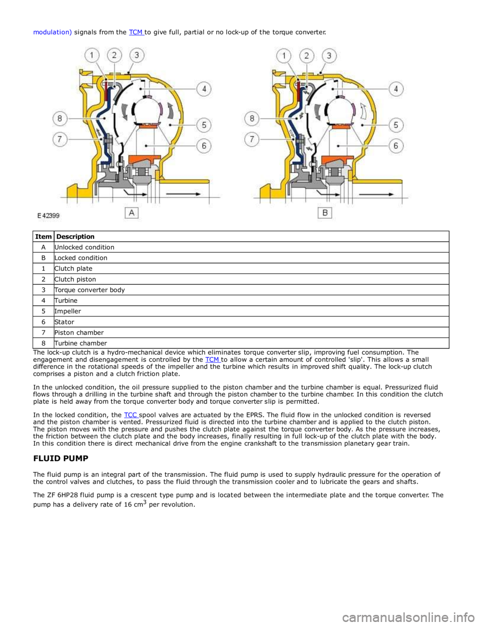
Item Description A Unlocked condition B Locked condition 1 Clutch plate 2 Clutch piston 3 Torque converter body 4 Turbine 5 Impeller 6 Stator 7 Piston chamber 8 Turbine chamber The lock-up clutch is a hydro-mechanical device which eliminates torque converter slip, improving fuel consumption. The
engagement and disengagement is controlled by the TCM to allow a certain amount of controlled 'slip'. This allows a small difference in the rotational speeds of the impeller and the turbine which results in improved shift quality. The lock-up clutch
comprises a piston and a clutch friction plate.
In the unlocked condition, the oil pressure supplied to the piston chamber and the turbine chamber is equal. Pressurized fluid
flows through a drilling in the turbine shaft and through the piston chamber to the turbine chamber. In this condition the clutch
plate is held away from the torque converter body and torque converter slip is permitted.
In the locked condition, the TCC spool valves are actuated by the EPRS. The fluid flow in the unlocked condition is reversed and the piston chamber is vented. Pressurized fluid is directed into the turbine chamber and is applied to the clutch piston.
The piston moves with the pressure and pushes the clutch plate against the torque converter body. As the pressure increases,
the friction between the clutch plate and the body increases, finally resulting in full lock-up of the clutch plate with the body.
In this condition there is direct mechanical drive from the engine crankshaft to the transmission planetary gear train.
FLUID PUMP
The fluid pump is an integral part of the transmission. The fluid pump is used to supply hydraulic pressure for the operation of
the control valves and clutches, to pass the fluid through the transmission cooler and to lubricate the gears and shafts.
The ZF 6HP28 fluid pump is a crescent type pump and is located between the intermediate plate and the torque converter. The
pump has a delivery rate of 16 cm3
per revolution.
Page 1591 of 3039

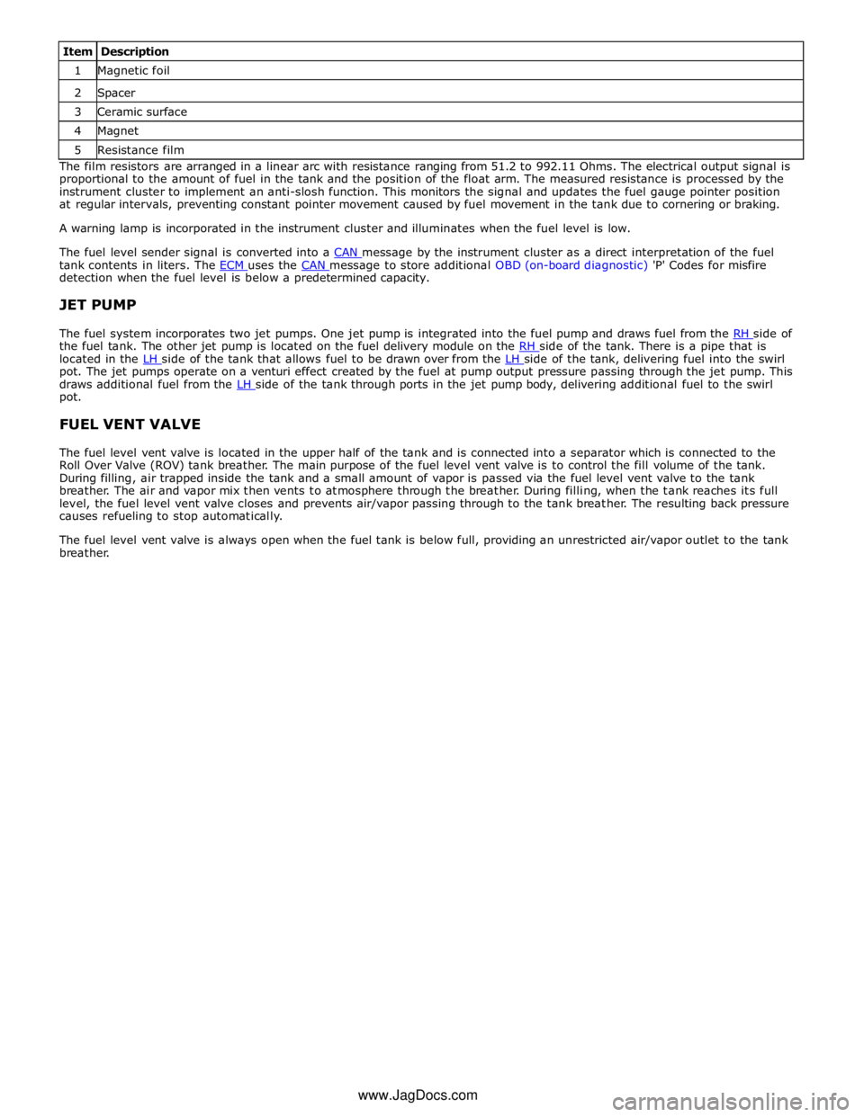
1 Magnetic foil 2 Spacer 3 Ceramic surface 4 Magnet 5 Resistance film The film resistors are arranged in a linear arc with resistance ranging from 51.2 to 992.11 Ohms. The electrical output signal is
proportional to the amount of fuel in the tank and the position of the float arm. The measured resistance is processed by the
instrument cluster to implement an anti-slosh function. This monitors the signal and updates the fuel gauge pointer position
at regular intervals, preventing constant pointer movement caused by fuel movement in the tank due to cornering or braking.
A warning lamp is incorporated in the instrument cluster and illuminates when the fuel level is low.
The fuel level sender signal is converted into a CAN message by the instrument cluster as a direct interpretation of the fuel tank contents in liters. The ECM uses the CAN message to store additional OBD (on-board diagnostic) 'P' Codes for misfire detection when the fuel level is below a predetermined capacity.
JET PUMP
The fuel system incorporates two jet pumps. One jet pump is integrated into the fuel pump and draws fuel from the RH side of the fuel tank. The other jet pump is located on the fuel delivery module on the RH side of the tank. There is a pipe that is located in the LH side of the tank that allows fuel to be drawn over from the LH side of the tank, delivering fuel into the swirl pot. The jet pumps operate on a venturi effect created by the fuel at pump output pressure passing through the jet pump. This
draws additional fuel from the LH side of the tank through ports in the jet pump body, delivering additional fuel to the swirl pot.
FUEL VENT VALVE
The fuel level vent valve is located in the upper half of the tank and is connected into a separator which is connected to the
Roll Over Valve (ROV) tank breather. The main purpose of the fuel level vent valve is to control the fill volume of the tank.
During filling, air trapped inside the tank and a small amount of vapor is passed via the fuel level vent valve to the tank
breather. The air and vapor mix then vents to atmosphere through the breather. During filling, when the tank reaches its full
level, the fuel level vent valve closes and prevents air/vapor passing through to the tank breather. The resulting back pressure
causes refueling to stop automatically.
The fuel level vent valve is always open when the fuel tank is below full, providing an unrestricted air/vapor outlet to the tank
breather.
www.JagDocs.com
Page 1663 of 3039

Climate Control System - General Information -
Lubricants, Fluids, Sealers and Adhesives
NOTE: NAS vehicles. Published: 29-Jan-2014
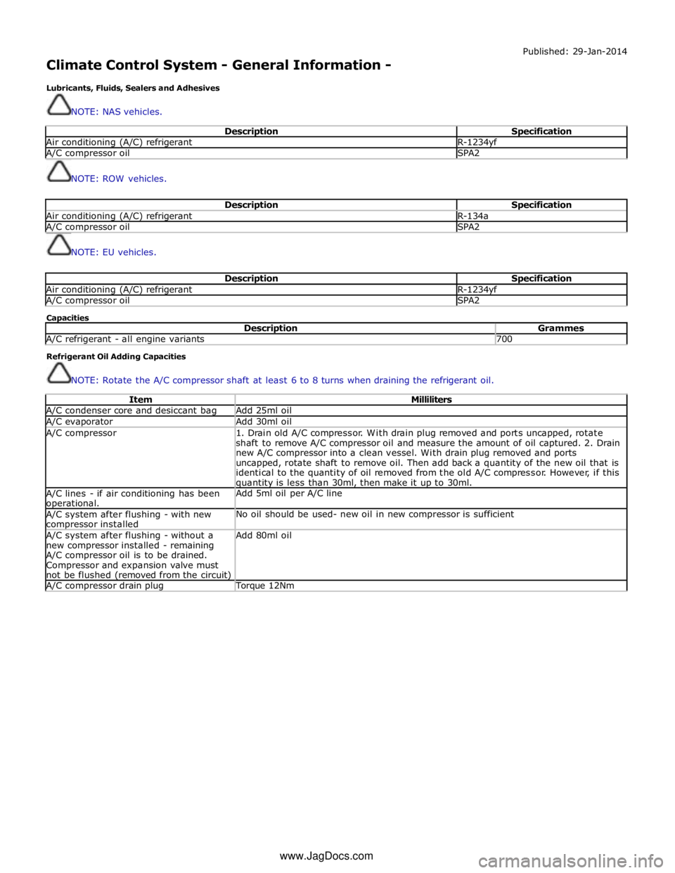
Description Specification Air conditioning (A/C) refrigerant R-1234yf A/C compressor oil SPA2
NOTE: ROW vehicles.
Description Specification Air conditioning (A/C) refrigerant R-134a A/C compressor oil SPA2
NOTE: EU vehicles.
Description Specification Air conditioning (A/C) refrigerant R-1234yf A/C compressor oil SPA2 Capacities
Description Grammes A/C refrigerant - all engine variants 700 Refrigerant Oil Adding Capacities
NOTE: Rotate the A/C compressor shaft at least 6 to 8 turns when draining the refrigerant oil.
Item Milliliters A/C condenser core and desiccant bag Add 25ml oil A/C evaporator Add 30ml oil A/C compressor
1. Drain old A/C compressor. With drain plug removed and ports uncapped, rotate
shaft to remove A/C compressor oil and measure the amount of oil captured. 2. Drain
new A/C compressor into a clean vessel. With drain plug removed and ports
uncapped, rotate shaft to remove oil. Then add back a quantity of the new oil that is
identical to the quantity of oil removed from the old A/C compressor. However, if this quantity is less than 30ml, then make it up to 30ml. A/C lines - if air conditioning has been operational. Add 5ml oil per A/C line A/C system after flushing - with new compressor installed No oil should be used- new oil in new compressor is sufficient A/C system after flushing - without a
new compressor installed - remaining
A/C compressor oil is to be drained.
Compressor and expansion valve must
not be flushed (removed from the circuit) Add 80ml oil A/C compressor drain plug Torque 12Nm www.JagDocs.com
Page 1670 of 3039

27. Close the valve on the oil charger.
28. Disconnect the yellow line from the refrigerant station.
29. Remove the cover from the oil charger.
30. Pour the correct quantity of refrigerant oil into the oil charger.
31. Install the cover to the oil charger.
32. Connect the yellow line to the refrigerant station.
33. Open the valve on the oil charger.
34. Move the pointer on the refrigerant gauge to mark the position of the
refrigerant drop.
35. Slowly open the correct valve on the refrigerant to allow the vacuum to
pull the refrigerant into the system.
36. Close the valve on the refrigerant station when the correct amount of
refrigerant has been drawn into the air conditioning system.
37. Turn the main switch 'OFF'.
38. Close the valves on the connections.
39. Disconnect the high and low pressure connections.