2010 JAGUAR XFR wiper fluid
[x] Cancel search: wiper fluidPage 191 of 3039

DTC Description Possible Causes Action B10A0-11
Wiper/ Washer Switch -
Circuit short to ground
Wash/wipe circuit - short to
ground
Refer to the electrical circuit diagrams and check
wash/wipe circuit for short to ground B10A0-15
Wiper/ Washer Switch -
Circuit short to battery
or open
Wash/wipe circuit - short to
power, open circuit
Carry out any pinpoint tests associated with this
DTC using the manufacturer approved diagnostic
system. Refer to the electrical circuit diagrams
and check wash/wipe circuit for short to power,
open circuit B10A6-11
Main Light Switch -
Circuit short to ground
Master lighting switch circuit
- short to ground
Refer to the electrical circuit diagrams and check
master lighting switch circuit for short to ground B10A6-15
Main Light Switch -
Circuit short to battery
or open
Master lighting switch circuit
- short to power, open
circuit
Carry out any pinpoint tests associated with this
DTC using the manufacturer approved diagnostic
system. Refer to the electrical circuit diagrams
and check master lighting switch circuit for short
to power, open circuit B112B-87
Steering Wheel Module -
Missing message
Steering wheel module
failure - slave node not
responding
Carry out any pinpoint tests associated with this
DTC using the manufacturer approved diagnostic
system. Refer to the electrical circuit diagrams
and check the clockspring LIN circuit for short,
open circuit. Suspect the clockspring, check and
install a new clockspring as required, refer to the
new module/component installation note at the
top of the DTC Index B115C-7A Transfer Fuel Pump -
Fluid leak or seal failure
Fuel pump system fault
Check for fuel system jet pump or jet pump fuel
level sensor fault B1A85-15
Ambient Light Sensor -
Circuit short to battery
or open
Autolamp sensor circuit -
short to power, open circuit
Carry out any pinpoint tests associated with this
DTC using the manufacturer approved diagnostic
system. Refer to the electrical circuit diagrams
and check autolamp sensor circuit for short to
power, open circuit B1B01-00
Key Transponder - No
sub type information
Operator only cycles one key
During transponder key
programming the instrument
cluster, smartcard docking
station or key loses
power/circuit failure
Faulty key during key
programming
Unable to program
transponder key due to
noise/EMC related error
Ensure all keys to be programmed are available.
Refer to electrical circuit diagrams and check
power and ground supply circuits to all relevant
modules. Replace faulty key and repeat key
programming. Check CAN network for
interference/EMC related issues B1B01-05
Key Transponder -
System programming
failures
Error following SCU
replacement
Smartcard docking station
power and ground supply
circuits - short, open circuit
LIN fault
Instrument cluster power
and ground supply circuits -
short, open circuit
Carry out any pinpoint tests associated with this
DTC using the manufacturer approved diagnostic
system. Perform the Immobilisation application
from the Set-up menu using the manufacturer
approved diagnostic system. Refer to the
electrical circuit diagrams and check smartcard
docking station power and ground supply circuits
for short, open circuit and instrument cluster
power and ground supply circuits for short, open
circuit. Check LIN communications between
smartcard docking station and instrument cluster B1B01-51
Key Transponder - Not
programmed
LIN fault
Instrument cluster power
and ground supply circuits -
short, open circuit
Key fault
Smartcard docking station
power and ground supply
circuits - short, open circuit
Attempted to program a non
Carry out any pinpoint tests associated with this
DTC using the manufacturer approved diagnostic
system. Check LIN communications between
smartcard docking station and instrument
cluster. Refer to the electrical circuit diagrams
and check smartcard docking station power and
ground supply circuits for short, open circuit and
instrument cluster power and ground supply
circuits for short, open circuit. Confirm www.JagDocs.com
Page 1800 of 3039

DTC Description Possible Cause Action B100D96
Column Lock
Authorisation -
Component
internal failure
Battery voltage at electric
steering column lock control
module too low
Torque load on steering
column
CAN fault
Electric steering column lock
control module - Internal
failure
Clear DTC, repeatedly lock and unlock car using the
key fob and retest
If fault persists, check that the vehicle battery supply
voltage is between 9-16 volts. Rectify as required
Ensure the column lock bolt movement is not
obstructed or restricted (the parked position of the
road wheels may be exerting a turning force through
the steering column, preventing the lock from
releasing. The steering wheel may need to be held
against the force to allow the column lock to
release). Clear DTC, repeatedly lock and unlock car
using the key fob and retest
If fault persists, complete a CAN network integrity
test using the manufacturers approved diagnostic
system. Alternatively, refer to the electrical circuit
diagrams and check CAN circuits between the central
junction box, the instrument cluster and the
electronic steering column lock. Refer to the electrical
circuit diagrams and check the central junction box,
the instrument cluster and the electronic steering
column lock power and ground supply circuits for short
circuit to ground, short circuit to power, open circuit,
high resistance. Repair circuit(s) as required. Clear
DTC, perform an on demand self-test and retest
If fault persists, check and install a new electric
steering column lock control module as required B102487 Start Control Unit
Smart card docking station
failure - slave node not
responding Carry out any pinpoint tests associated with this DTC using
the manufacturer approved diagnostic system. Refer to the
electrical circuit diagrams and check the smart card docking
station LIN circuit for short, open circuit. Suspect the smart
card docking station, check and install a new docking station
as required, refer to the new module/component installation
note at the top of the DTC Index B104611
Front Fog Lamp
Control Switch
Fog lamp switch circuit - short
to ground Refer to the electrical circuit diagrams and check fog lamp
switch circuit for short to ground B104615
Front Fog Lamp
Control Switch
Fog lamp switch circuit - short
to power, open circuit Refer to the electrical circuit diagrams and check fog lamp
switch circuit for short to power, open circuit B104811
Brake Fluid Level
Switch
Brake fluid level switch circuit
- short to ground Refer to the electrical circuit diagrams and check brake fluid
level switch circuit for short to ground B10A011
Wiper/ Washer
Switch
Wash/wipe circuit - short to
ground Refer to the electrical circuit diagrams and check wash/wipe
circuit for short to ground B10A015
Wiper/ Washer
Switch
Wash/wipe circuit - short to
power, open circuit Carry out any pinpoint tests associated with this DTC using
the manufacturer approved diagnostic system. Refer to the
electrical circuit diagrams and check wash/wipe circuit for
short to power, open circuit B10A611 Main Light Switch
Master lighting switch circuit -
short to ground Refer to the electrical circuit diagrams and check master
lighting switch circuit for short to ground B10A615 Main Light Switch
Master lighting switch circuit -
short to power, open circuit Carry out any pinpoint tests associated with this DTC using
the manufacturer approved diagnostic system. Refer to the
electrical circuit diagrams and check master lighting switch
circuit for short to power, open circuit B112B87
Steering Wheel
Module
Steering wheel module failure
- slave node not responding Carry out any pinpoint tests associated with this DTC using
the manufacturer approved diagnostic system. Refer to the
electrical circuit diagrams and check the clockspring LIN
circuit for short, open circuit. Suspect the clockspring, check
and install a new clockspring as required, refer to the new
module/component installation note at the top of the DTC
Index B115C7A
Transfer Fuel
Pump
Fuel pump system fault Check for fuel system jet pump or jet pump fuel level sensor
fault B1A8515
Ambient Light
Sensor
Autolamp sensor circuit - short
to power, open circuit Carry out any pinpoint tests associated with this DTC using
the manufacturer approved diagnostic system. Refer to the
electrical circuit diagrams and check autolamp sensor circuit
for short to power, open circuit
Page 2172 of 3039
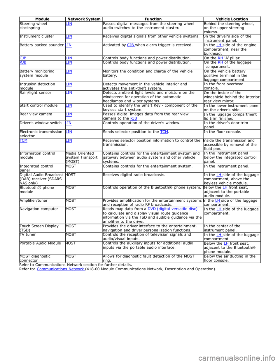
Module Network System Function Vehicle Location
Steering wheel
clockspring LIN Passes digital messages from the steering wheel
audio switches to the instrument cluster. Behind the steering wheel,
on the upper steering
column.
Instrument cluster LIN Receives digital signals from other vehicle systems. On the driver's side of the
instrument panel.
Battery backed sounder LIN Activated by CJB when alarm trigger is received. In the LH side of the engine compartment, near the
bulkhead.
CJB LIN Controls body functions and power distribution. On the RH 'A' pillar.
RJB LIN Controls body functions and power distribution. On the RH of the luggage compartment.
Battery monitoring
system module
Intrusion detection
module LIN Monitors the condition and charge of the vehicle
battery.
LIN Detects movement in the vehicle interior and
activates the anti-theft system. On the vehicle battery
positive terminal in the
luggage compartment.
In the front overhead
console.
Rain/light sensor LIN Detects ambient light levels and moisture on the
windscreen for operation of the automatic
headlamps and wiper systems.
Start control module LIN Used to identify the Smart Key - component of the
keyless start system.
Rear view camera LIN Passes digital images data from the rear view
camera to the RJB On the inside of the
windshield behind the interior
rear view mirror.
In the lower instrument panel
on the driver's side.
In the luggage compartment
lid trim finisher.
Driver's window switch LIN Controls operation of the driver's window. In the driver's door trim
panel.
Electronic transmission
selector LIN Sends selector position to the TCM. In the floor console. TCM LIN Receives selector position information to control the Inside the transmission and
Information control
module
Media Oriented
System Transport
(MOST) transmission.
Contains controls for the entertainment system and
gateway between audio system and other vehicle
systems. accessible by removal of the
fluid pan.
In the instrument panel
below the integrated control
panel.
Integrated control
panel MOST Contains controls for the entertainment system. In the instrument panel.
Digital Audio Broadcast MOST Receives digital radio broadcasts. In the LH side of the luggage (DAB) receiver (SDARS
NAS only)
Bluetooth® phone
module compartment, above the
keyless vehicle module.
MOST Controls operation of the Bluetooth® phone system. Below the LH front seat, adjacent to the portable
audio module.
Amplifier/tuner MOST Provides amplification for the entertainment systems In the LH side of the luggage and reception of radio RF broadcasts.
Navigation computer MOST Reads map data from a DVD (digital versatile disc)
to calculate and display visual route guidance
information via the TSD and audible guidance via the
amplifier to the driver. compartment.
In the LH side of the luggage compartment.
Touch Screen Display
(TSD) MOST Provides the driver interface to the entertainment,
navigation and driver personalization functions. In the center of the
instrument panel.
TV tuner MOST Controls the reception of television signals and
audio/visual inputs.
Portable Audio Module MOST Controls the auxiliary inputs for additional audio
inputs via the portable audio interface. In the LH side of the luggage compartment.
Below the LH front seat, adjacent to the Bluetooth®
phone module.
MOST diagnostic
connector MOST Allows for diagnostic fault detection of the MOST
ring. Below the air ducting in the
floor console.
Refer to Communications Network section for further details.
Refer to: Communications Network (418-00 Module Communications Network, Description and Operation).
Page 2536 of 3039
Published: 11-May-2011
Wipers and Washers - Wipers and Washers - System Operation and
Component Description
Description and Operation
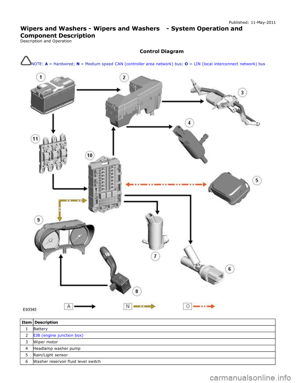
Control Diagram
NOTE: A = Hardwired; N = Medium speed CAN (controller area network) bus; O = LIN (local interconnect network) bus
Item Description 1 Battery 2 EJB (engine junction box) 3 Wiper motor 4 Headlamp washer pump 5 Rain/Light sensor 6 Washer reservoir fluid level switch
Page 2537 of 3039
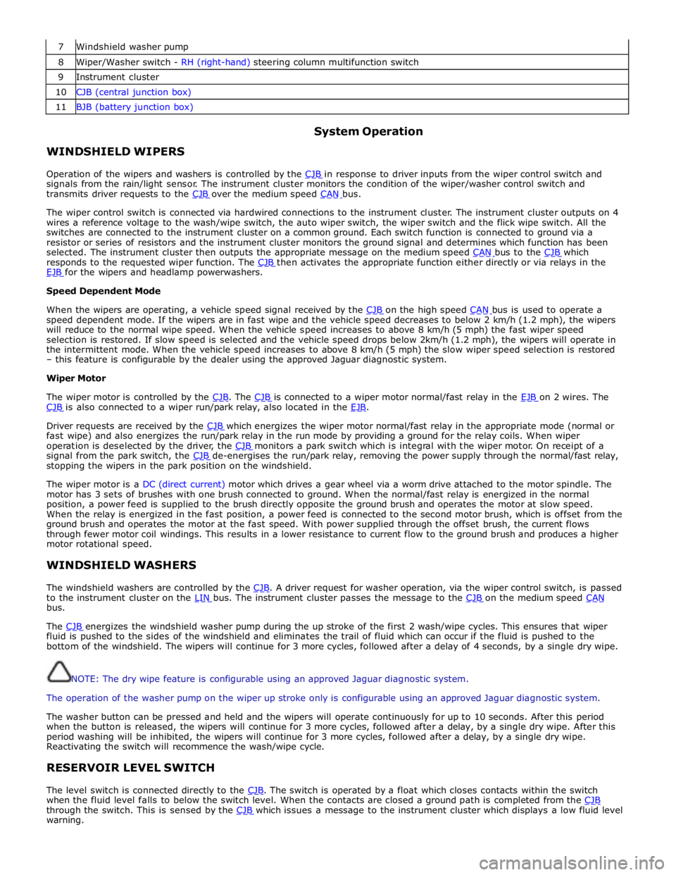
7 Windshield washer pump 8 Wiper/Washer switch - RH (right-hand) steering column multifunction switch 9 Instrument cluster 10 CJB (central junction box) 11 BJB (battery junction box)
WINDSHIELD WIPERS System Operation
Operation of the wipers and washers is controlled by the CJB in response to driver inputs from the wiper control switch and signals from the rain/light sensor. The instrument cluster monitors the condition of the wiper/washer control switch and
transmits driver requests to the CJB over the medium speed CAN bus.
The wiper control switch is connected via hardwired connections to the instrument cluster. The instrument cluster outputs on 4
wires a reference voltage to the wash/wipe switch, the auto wiper switch, the wiper switch and the flick wipe switch. All the
switches are connected to the instrument cluster on a common ground. Each switch function is connected to ground via a
resistor or series of resistors and the instrument cluster monitors the ground signal and determines which function has been
selected. The instrument cluster then outputs the appropriate message on the medium speed CAN bus to the CJB which responds to the requested wiper function. The CJB then activates the appropriate function either directly or via relays in the EJB for the wipers and headlamp powerwashers. Speed Dependent Mode
When the wipers are operating, a vehicle speed signal received by the CJB on the high speed CAN bus is used to operate a speed dependent mode. If the wipers are in fast wipe and the vehicle speed decreases to below 2 km/h (1.2 mph), the wipers
will reduce to the normal wipe speed. When the vehicle speed increases to above 8 km/h (5 mph) the fast wiper speed
selection is restored. If slow speed is selected and the vehicle speed drops below 2km/h (1.2 mph), the wipers will operate in
the intermittent mode. When the vehicle speed increases to above 8 km/h (5 mph) the slow wiper speed selection is restored
– this feature is configurable by the dealer using the approved Jaguar diagnostic system.
Wiper Motor
The wiper motor is controlled by the CJB. The CJB is connected to a wiper motor normal/fast relay in the EJB on 2 wires. The CJB is also connected to a wiper run/park relay, also located in the EJB.
Driver requests are received by the CJB which energizes the wiper motor normal/fast relay in the appropriate mode (normal or fast wipe) and also energizes the run/park relay in the run mode by providing a ground for the relay coils. When wiper
operation is deselected by the driver, the CJB monitors a park switch which is integral with the wiper motor. On receipt of a signal from the park switch, the CJB de-energises the run/park relay, removing the power supply through the normal/fast relay, stopping the wipers in the park position on the windshield.
The wiper motor is a DC (direct current) motor which drives a gear wheel via a worm drive attached to the motor spindle. The
motor has 3 sets of brushes with one brush connected to ground. When the normal/fast relay is energized in the normal
position, a power feed is supplied to the brush directly opposite the ground brush and operates the motor at slow speed.
When the relay is energized in the fast position, a power feed is connected to the second motor brush, which is offset from the
ground brush and operates the motor at the fast speed. With power supplied through the offset brush, the current flows
through fewer motor coil windings. This results in a lower resistance to current flow to the ground brush and produces a higher
motor rotational speed.
WINDSHIELD WASHERS
The windshield washers are controlled by the CJB. A driver request for washer operation, via the wiper control switch, is passed to the instrument cluster on the LIN bus. The instrument cluster passes the message to the CJB on the medium speed CAN bus.
The CJB energizes the windshield washer pump during the up stroke of the first 2 wash/wipe cycles. This ensures that wiper fluid is pushed to the sides of the windshield and eliminates the trail of fluid which can occur if the fluid is pushed to the
bottom of the windshield. The wipers will continue for 3 more cycles, followed after a delay of 4 seconds, by a single dry wipe.
NOTE: The dry wipe feature is configurable using an approved Jaguar diagnostic system.
The operation of the washer pump on the wiper up stroke only is configurable using an approved Jaguar diagnostic system.
The washer button can be pressed and held and the wipers will operate continuously for up to 10 seconds. After this period
when the button is released, the wipers will continue for 3 more cycles, followed after a delay, by a single dry wipe. After this
period washing will be inhibited, the wipers will continue for 3 more cycles, followed after a delay, by a single dry wipe.
Reactivating the switch will recommence the wash/wipe cycle.
RESERVOIR LEVEL SWITCH
The level switch is connected directly to the CJB. The switch is operated by a float which closes contacts within the switch when the fluid level falls to below the switch level. When the contacts are closed a ground path is completed from the CJB through the switch. This is sensed by the CJB which issues a message to the instrument cluster which displays a low fluid level warning.
Page 2538 of 3039
HEADLAMP POWERWASHERS
The headlamp powerwash is activated when the driver requests windshield washer operation. The CJB receives the driver request via a CAN bus message from the instrument cluster. The CJB then checks for an exterior lights active signal and that a low washer fluid level signal is not present.
The CJB outputs a control voltage to a headlamp powerwash pump relay located in the EJB. The relay is energized by the CJB for a pre-determined period to allow the headlamp telescopic washers to operate.
The CJB monitors the driver washer requests and only operates the headlamp powerwash on every fourth request for windshield washer operation, provided that 10 minutes have elapsed since the last headlamp powerwash operation. The
powerwash sequence is reset when the headlamps or the ignition is switched off.
NOTE: If a low fluid reservoir level is present the CJB prohibits headlamp powerwash.
RAIN/LIGHT SENSOR
On receiving a request for automatic windshield wiper operation, the CJB interprets LIN bus messages received from the rain sensor. The rain sensor provides LIN bus messages with values ranging from 0 to 7.
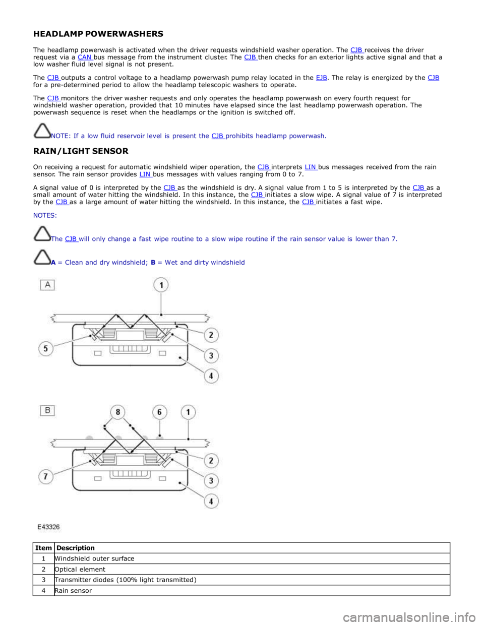
A signal value of 0 is interpreted by the CJB as the windshield is dry. A signal value from 1 to 5 is interpreted by the CJB as a small amount of water hitting the windshield. In this instance, the CJB initiates a slow wipe. A signal value of 7 is interpreted by the CJB as a large amount of water hitting the windshield. In this instance, the CJB initiates a fast wipe. NOTES:
The CJB will only change a fast wipe routine to a slow wipe routine if the rain sensor value is lower than 7.
A = Clean and dry windshield; B = Wet and dirty windshield
Item Description 1 Windshield outer surface 2 Optical element 3 Transmitter diodes (100% light transmitted) 4 Rain sensor
Page 2541 of 3039
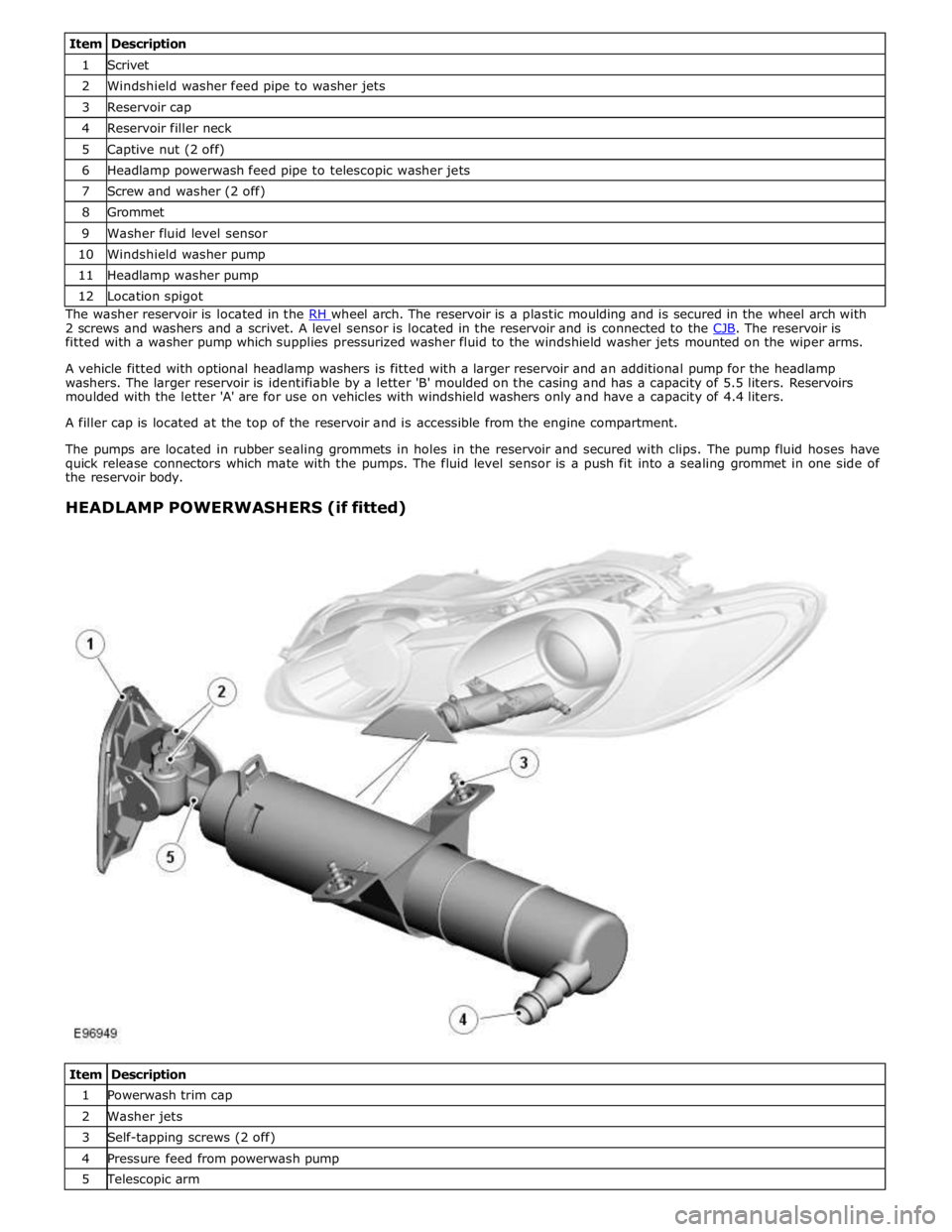
1 Scrivet 2 Windshield washer feed pipe to washer jets 3 Reservoir cap 4 Reservoir filler neck 5 Captive nut (2 off) 6 Headlamp powerwash feed pipe to telescopic washer jets 7 Screw and washer (2 off) 8 Grommet 9 Washer fluid level sensor 10 Windshield washer pump 11 Headlamp washer pump 12 Location spigot The washer reservoir is located in the RH wheel arch. The reservoir is a plastic moulding and is secured in the wheel arch with 2 screws and washers and a scrivet. A level sensor is located in the reservoir and is connected to the CJB. The reservoir is fitted with a washer pump which supplies pressurized washer fluid to the windshield washer jets mounted on the wiper arms.
A vehicle fitted with optional headlamp washers is fitted with a larger reservoir and an additional pump for the headlamp
washers. The larger reservoir is identifiable by a letter 'B' moulded on the casing and has a capacity of 5.5 liters. Reservoirs
moulded with the letter 'A' are for use on vehicles with windshield washers only and have a capacity of 4.4 liters.
A filler cap is located at the top of the reservoir and is accessible from the engine compartment.
The pumps are located in rubber sealing grommets in holes in the reservoir and secured with clips. The pump fluid hoses have
quick release connectors which mate with the pumps. The fluid level sensor is a push fit into a sealing grommet in one side of
the reservoir body.
HEADLAMP POWERWASHERS (if fitted)
Item Description 1 Powerwash trim cap 2 Washer jets 3 Self-tapping screws (2 off) 4 Pressure feed from powerwash pump 5 Telescopic arm
Page 2542 of 3039
On vehicles with headlamp powerwash, each headlamp assembly is fitted with a headlamp powerwasher. The powerwasher is
located on the underside of the headlamp assembly. The powerwasher is located in a clip at the front of the headlamp and
secured with 2 self tapping screws to the headlamp body.
The powerwasher is a telescopic unit which extends forwards from the headlamp assembly under washer fluid pressure
supplied by the headlamp powerwash pump. When the pump pressure decreases the powerwasher is automatically retracted
back into the housing. The outer end of the powerwasher is fitted with a trim which blends the powerwasher into the headlamp
when it is not operating. The powerwasher has two washer jets which direct washer fluid under high pressure onto the
headlamp lens when the powerwasher is extended.
RAIN/LIGHT SENSOR
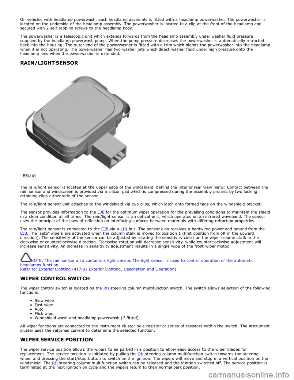
The rain/light sensor is located at the upper edge of the windshield, behind the interior rear view mirror. Contact between the
rain sensor and windscreen is provided via a silicon pad which is compressed during the assembly process by two locking
retaining clips either side of the sensor.
The rain/light sensor unit attaches to the windshield via two clips, which latch onto formed tags on the windshield bracket.
The sensor provides information to the CJB for the optimum wiper operation for the prevailing conditions to maintain the shield in a clear condition at all times. The rain/light sensor is an optical unit, which operates on an infrared waveband. The sensor
uses the principle of the laws of reflection on interfacing surfaces between materials with differing refraction properties.
The rain/light sensor is connected to the CJB via a LIN bus. The sensor also receives a hardwired power and ground from the CJB. The 'auto' wipers are activated when the column stalk is moved to position 1 (first position from off in the upward direction). The sensitivity of the sensor can be adjusted by rotating the sensitivity collar on the wiper column stalk in the
clockwise or counterclockwise direction. Clockwise rotation will decrease sensitivity, while counterclockwise adjustment will
increase sensitivity. An increase in sensitivity adjustment results in a single wipe of the front wiper motor.
NOTE: The rain sensor also contains a light sensor. The light sensor is used to control operation of the automatic
headlamps function.
Refer to: Exterior Lighting (417-01 Exterior Lighting, Description and Operation).
WIPER CONTROL SWITCH
The wiper control switch is located on the RH steering column multifunction switch. The switch allows selection of the following functions:
Slow wipe
Fast wipe
Auto
Flick wipe
Windshield wash and headlamp powerwash (if fitted).
All wiper functions are connected to the instrument cluster by a resistor or series of resistors within the switch. The instrument
cluster uses the returned current to determine the selected function.
WIPER SERVICE POSITION
The wiper service position allows the wipers to be parked in a position to allow easy access to the wiper blades for
replacement. The service position is initiated by pulling the RH steering column multifunction switch towards the steering wheel and pressing the start/stop button to switch on the ignition. The wipers will move and stop in a vertical position on the
windshield. The RH steering column multifunction switch can be released and the ignition switched off. The service position is terminated at the next ignition on cycle and the wipers return to their normal park position.