2010 JAGUAR XFR alarm
[x] Cancel search: alarmPage 24 of 3039

System Operation and Component DescriptionDiagnosis and TestingAnti-Theft - ActiveRemoval and InstallationAnti-Theft Alarm Horn (86.52.03)419-01B: Anti-Theft - Passive
Description and OperationComponent Location
Overview
System Operation and Component DescriptionDiagnosis and TestingAnti-Theft - Passive419-05: Telematics
Diagnosis and TestingTelematics419-07: Navigation System
Description and Operation Diagnosis and TestingNavigation SystemRemoval and InstallationNavigation System Antenna (86.62.06)
Navigation System Module (86.62.05)419-08: Cellular Phone
Removal and InstallationBluetooth Module419-10: Multifunction Electronic ModulesSpecificationDescription and OperationComponent Location
Overview
System Operation and Component DescriptionDiagnosis and TestingDriver Door Module (DDM)
Remote Keyless Entry (RKE) Module
Passenger Door Module (PDM)Removal and InstallationDriver Door Module (DDM)
Driver Seat Module (DSM)
Passenger Door Module (PDM)
Rear Door Module (RDM)5: Body and Paint
501: Body and Paint
501-02: Front End Body Panels
Page 1715 of 3039
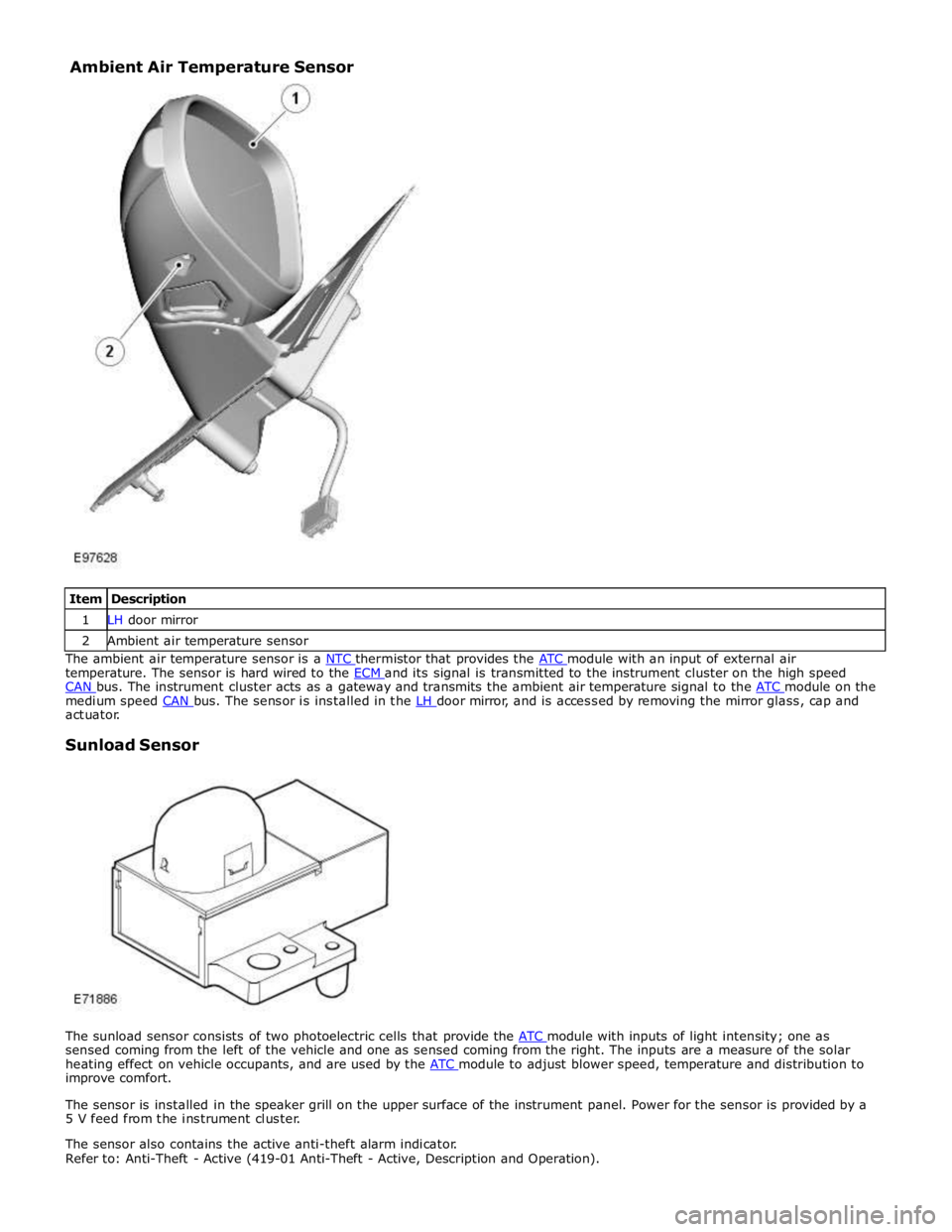
1 LH door mirror 2 Ambient air temperature sensor The ambient air temperature sensor is a NTC thermistor that provides the ATC module with an input of external air temperature. The sensor is hard wired to the ECM and its signal is transmitted to the instrument cluster on the high speed CAN bus. The instrument cluster acts as a gateway and transmits the ambient air temperature signal to the ATC module on the medium speed CAN bus. The sensor is installed in the LH door mirror, and is accessed by removing the mirror glass, cap and actuator.
Sunload Sensor
The sunload sensor consists of two photoelectric cells that provide the ATC module with inputs of light intensity; one as sensed coming from the left of the vehicle and one as sensed coming from the right. The inputs are a measure of the solar
heating effect on vehicle occupants, and are used by the ATC module to adjust blower speed, temperature and distribution to improve comfort.
The sensor is installed in the speaker grill on the upper surface of the instrument panel. Power for the sensor is provided by a
5 V feed from the instrument cluster.
The sensor also contains the active anti-theft alarm indicator.
Refer to: Anti-Theft - Active (419-01 Anti-Theft - Active, Description and Operation). Ambient Air Temperature Sensor
Page 1783 of 3039
Published: 11-May-2011
Instrument Cluster - Instrument Cluster - System Operation and Component Description
Description and Operation
Control Diagram
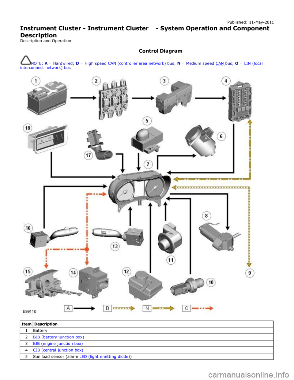
NOTE: A = Hardwired; D = High speed CAN (controller area network) bus; N = Medium speed CAN bus; O = LIN (local interconnect network) bus
Item Description 1 Battery 2 BJB (battery junction box) 3 EJB (engine junction box) 4 CJB (central junction box) 5 Sun load sensor (alarm LED (light emitting diode))
Page 1827 of 3039
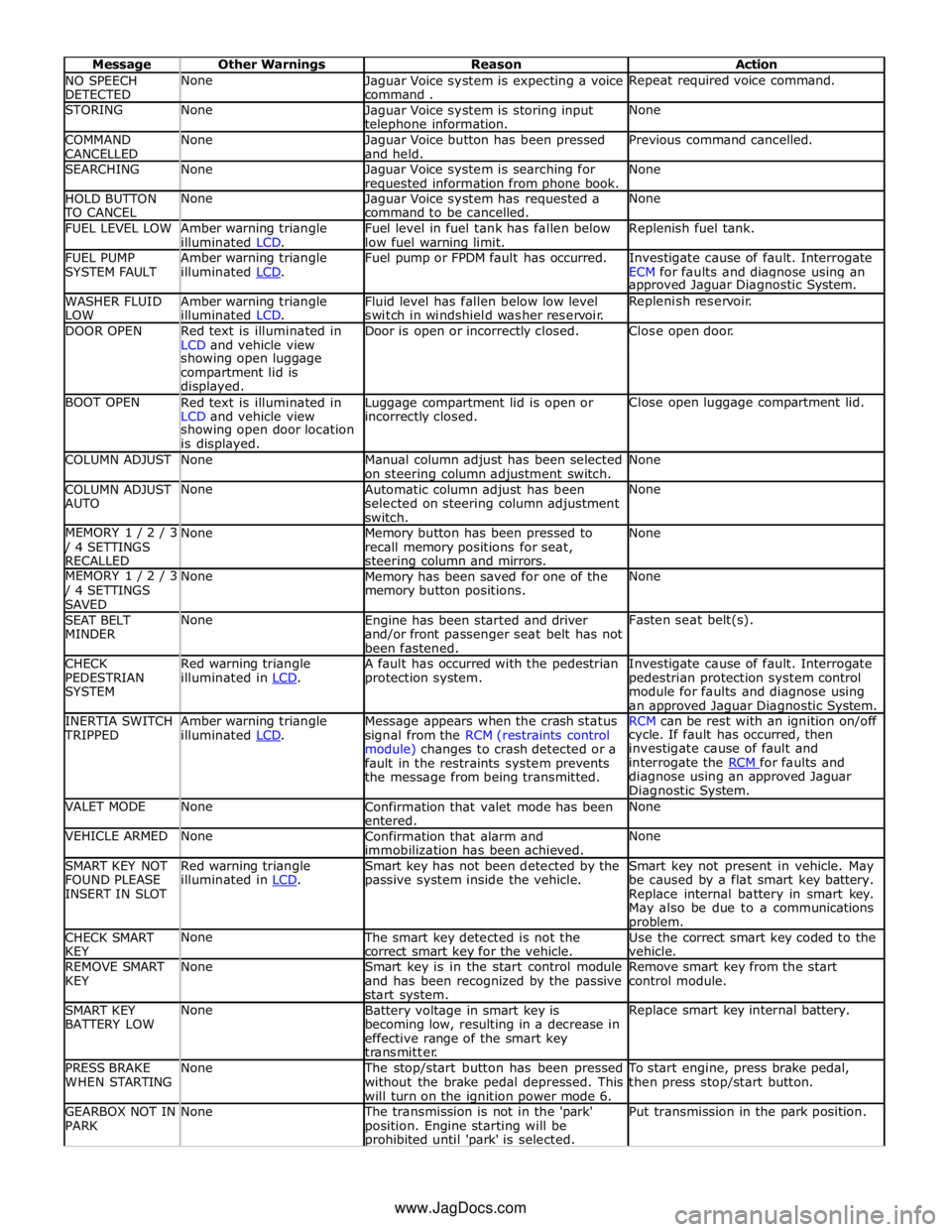
NO SPEECH
DETECTED None
Jaguar Voice system is expecting a voice
command . Repeat required voice command. STORING None
Jaguar Voice system is storing input telephone information. None COMMAND
CANCELLED None
Jaguar Voice button has been pressed
and held. Previous command cancelled. SEARCHING None
Jaguar Voice system is searching for requested information from phone book. None HOLD BUTTON TO CANCEL None
Jaguar Voice system has requested a
command to be cancelled. None FUEL LEVEL LOW
Amber warning triangle
illuminated LCD. Fuel level in fuel tank has fallen below
low fuel warning limit. Replenish fuel tank. FUEL PUMP
SYSTEM FAULT Amber warning triangle
illuminated LCD. Fuel pump or FPDM fault has occurred.
Investigate cause of fault. Interrogate
ECM for faults and diagnose using an approved Jaguar Diagnostic System. WASHER FLUID
LOW Amber warning triangle
illuminated LCD. Fluid level has fallen below low level
switch in windshield washer reservoir. Replenish reservoir. DOOR OPEN
Red text is illuminated in
LCD and vehicle view Door is open or incorrectly closed. Close open door. showing open luggage
compartment lid is
displayed. BOOT OPEN
Red text is illuminated in
LCD and vehicle view Luggage compartment lid is open or incorrectly closed. Close open luggage compartment lid. showing open door location
is displayed. COLUMN ADJUST None
Manual column adjust has been selected
on steering column adjustment switch. None COLUMN ADJUST
AUTO None
Automatic column adjust has been
selected on steering column adjustment
switch. None MEMORY 1 / 2 / 3 / 4 SETTINGS
RECALLED None
Memory button has been pressed to
recall memory positions for seat, steering column and mirrors. None MEMORY 1 / 2 / 3 / 4 SETTINGS
SAVED None
Memory has been saved for one of the
memory button positions. None SEAT BELT
MINDER None
Engine has been started and driver
and/or front passenger seat belt has not
been fastened. Fasten seat belt(s). CHECK
PEDESTRIAN
SYSTEM Red warning triangle
illuminated in LCD. A fault has occurred with the pedestrian
protection system. Investigate cause of fault. Interrogate
pedestrian protection system control
module for faults and diagnose using
an approved Jaguar Diagnostic System. INERTIA SWITCH TRIPPED Amber warning triangle
illuminated LCD. Message appears when the crash status
signal from the RCM (restraints control
module) changes to crash detected or a
fault in the restraints system prevents
the message from being transmitted. RCM can be rest with an ignition on/off cycle. If fault has occurred, then
investigate cause of fault and
interrogate the RCM for faults and diagnose using an approved Jaguar
Diagnostic System. VALET MODE None
Confirmation that valet mode has been
entered. None VEHICLE ARMED None
Confirmation that alarm and
immobilization has been achieved. None SMART KEY NOT
FOUND PLEASE
INSERT IN SLOT Red warning triangle
illuminated in LCD. Smart key has not been detected by the
passive system inside the vehicle. Smart key not present in vehicle. May
be caused by a flat smart key battery.
Replace internal battery in smart key.
May also be due to a communications problem. CHECK SMART
KEY None The smart key detected is not the
correct smart key for the vehicle. Use the correct smart key coded to the
vehicle. REMOVE SMART
KEY None
Smart key is in the start control module
and has been recognized by the passive
start system. Remove smart key from the start
control module. SMART KEY
BATTERY LOW None
Battery voltage in smart key is
becoming low, resulting in a decrease in
effective range of the smart key
transmitter. Replace smart key internal battery. PRESS BRAKE
WHEN STARTING None The stop/start button has been pressed
without the brake pedal depressed. This
will turn on the ignition power mode 6. To start engine, press brake pedal,
then press stop/start button. GEARBOX NOT IN
PARK None The transmission is not in the 'park'
position. Engine starting will be prohibited until 'park' is selected. Put transmission in the park position. www.JagDocs.com
Page 1871 of 3039

Published: 21-Dec-2012
Battery and Charging System - General Information - Quiescent Drain
Description and Operation
VEHICLE QUIESCENT CURRENT TESTING
On vehicles fitted with a Battery Monitoring System (BMS), the diagnostic routine for quiescent drain testing in the approved
Jaguar or Land Rover diagnostic system should be utilized.
If a customer complains of a vehicle battery that discharges continuously or when left for a prolonged period of time, it is
recommended that a quiescent drain test is performed as described below.
The battery drain should be measured using the approved Jaguar or Land Rover diagnostic system or a Digital Multi-Meter
(DVOM). A procedure for quiescent drain measurement using the diagnostic system is available in the Diagnosis and Testing
section of the Workshop Manual. The vehicle should be in the locked/armed state (for example vehicle alarm fully armed), all
doors, engine and luggage compartment lids are open and latched (so as to appear closed from an electrical point of view).
The test should take place after the vehicle has entered shutdown mode. The time taken for this to occur after the ignition is
switched off varies according to model (Refer to the Topix On line resource for details).
When the vehicle is armed, the effect of the security system Light Emitting Diode (LED) flashing is to cause a pulsation in the
measured current drain. In this case, either the average current should be taken (using a Digital Multi- Meter (DVOM) with an
averaging system) or the current reading taken, ignoring the brief high current peaks.
EQUIPMENT
Approved Jaguar or Land Rover diagnostic system with current probeOR Digital Multi-Meter (DVOM) with current probe.
METHOD OF MEASUREMENT
Using an Approved Jaguar or Land Rover Diagnostic System.
1. Switch off all electrical loads and ensure that the ignition is off
2. Connect the current probe to the approved Jaguar or Land Rover diagnostic system
3. Calibrate the probe
4. Install a clamp around the battery lead/junction box lead
5. Go to the Quiescent Current Testing section in this procedure
Using a digital multimeter
Do not use an in-line DVOM to measure the quiescent drain on vehicles fitted with an electronic throttle (for example XK 2006
onwards). The current exceeds the maximum amount the fuse in the DVOM is capable of handling.
1. Switch off all electrical loads and ensure that the ignition is off
2. Connect the current probe to the digital multmeter
3. Calibrate the probe
4. Install a clamp around the battery lead/junction box lead
5. Go to the Quiescent Current Testing section in this procedure
QUIESCENT CURRENT TESTING
1. Switch ignition to ‘on’ or select ignition mode in keyless vehicles and switch to ‘off’ (do not crank)
2. Remove key from ignition switch (if equipped)
3. Open and latch all doors, hood and luggage compartment lid
4. Lock the vehicle using the remote function on the remote handset. (Single lock only to avoid volumetric alarm arming)
5. Remove any other potential electrical drains such as accessories plugged into accessory sockets
6. Record the amperage readings after the shutdown period referenced in the Topix on line resource for details. Note all
cars from 10MY onwards and XK from 07MY and XF from 08MY should be less than 30mA after 30 minutes
7. Record the final reading on the battery report form
The preferred method of testing following an excessive current consumption figure is to use a current probe around individual
junction box leads to the various suspected circuits to identify a potential cause. This is in preference to the old method of
removing fuses for the following reasons:
The drain may be caused by a module remaining active and preventing the quiescent drain from reducing to normal
levels
The drain may be caused by a relay winding that is activated. Pulling the fuse can allow this to ‘reset’ and the drain will
be lost and go un-diagnosed
QUIESCENT DRAIN - TYPICAL VALUES
NOTE: The quiescent drain after the initial shutdown period should not exceed the value shown in the table.
Jaguar Quiescent Drain Values
MODEL SHUT DOWN PERIOD (minutes) TYPICAL VALUES BATTERY DRAIN (mA) XJS 3.2 60 <30 Sovereign 3.2 60 <37.3
Page 2027 of 3039
by Field Effect Transistors (FET's). The FET's can detect overloads and short circuits and respond to heat generated by
increased current flow caused by a short circuit.
On a normal conventionally protected circuit this would cause a fuse to blow. The FET's respond to the heat increase and
disconnect the power supply to the affected circuit. When the fault is rectified or the FET has cooled, the FET will reset and
operate the circuit normally. If the fault persists the FET will cycle, disconnecting and reconnecting the power supply.
The CJB and the RJB store fault codes which can be retrieved using a Jaguar approved diagnostic system. The fault code will identify that there is a fault on a particular output circuit which will assist with fault diagnosis and detection.
Alarm Indications
The exterior lighting system is used for alarm arm and disarm requests to show alarm system status.
When the driver locks and arms the vehicle, a visual indication of a successful lock and arm request is displayed to the driver
by a single flash of the hazard flashers. If the vehicle is superlocked, then the hazard flashers will flash a second time (200 ms
off and 200 ms on) to confirm the superlock request.
If the alarm is activated, the hazard flashers are operated for 10, 30 second cycles of 200 ms on and 200 ms off, with a 10
second delay between each cycle.
NOTE: On North American Specification (NAS) vehicles, the delay between the cycle when the alarm is activated is 60
seconds.
Lights on Warning
When the ignition is in the off power mode 0 or accessory power mode 4 and the lighting control switch is in the side lamp or
headlamp position, a warning chime will sound if the driver's door is opened. This indicates to the driver that the exterior
lights have been left switched on.
The chime is generated from the instrument cluster sounder on receipt of a lights on signal, a driver's door open signal and an
ignition off power mode 0 or accessory power mode 4 signal via a medium speed CAN bus signal from the CJB. Headlamp Timer
The RJB controls the headlamp timer function which allows the headlamps to remain on for a period of time after leaving the vehicle. This is a driver convenience feature which illuminates the driveway after leaving the vehicle.
To operate the timer function the lighting control switch must be in one of the three headlamp timer positions when the
ignition status is changed from ignition on power mode 6 to the off power mode 0. The timer function will then be initiated and
the low beam headlamps will be illuminated for the selected timer period.
NOTE: If the lighting switch is in the AUTO position, the headlamp timer will not function when the ignition is changed to
off power mode 0.
When the lighting control switch is in the autolamp exit delay position, the lighting control switch reference voltage flows
through 4 of the resistors. The returned signal voltage is detected by the instrument cluster which outputs a message on the
medium speed CAN bus to the RJB that autolamps has been selected.
Depending on the selected exit delay position, the reference voltage to the autolamp exit delay switch is routed through 3, 2
or 1 resistors which is detected by the instrument cluster. The cluster outputs a message on the medium speed CAN bus to the RJB that autolamp exit delay period has been selected at 30, 60 or 120 seconds respectively. Crash Signal Activation
When a crash signal is transmitted from the RCM (restraints control module), the RJB activates the hazard flashers. The hazard flashers continue to operate until the ignition is in the off power mode 0 or accessory power mode 6. Once this ignition state
has occurred, the RCM will cease to transmit the crash signal.
LIGHTING CONTROL SWITCH
The instrument cluster outputs 2 reference voltages to the rotary lighting control switch; one feed being supplied to the light
selection function of the switch and the second feed being supplied to the auto headlamp exit delay function. The switch
position is determined by instrument cluster by the change in returned signal voltage which is routed through up to 4 resistors
in series depending on the selection made.
OFF - When the lighting control switch is in the off position, the reference voltage flows through 1 of the resistors. The
returned signal voltage is detected by the instrument cluster which outputs a message on the medium speed CAN bus to the CJB that no lighting selection is made. The reference voltage to the auto headlamp exit delay switch is routed through 4 resistors which is detected by the instrument cluster which outputs a message on the medium speed CAN bus to the CJB that auto headlamp or exit delay has not been selected.
SIDE LAMPS - When the lighting control switch is in the side lamp position, the reference voltage flows through 2 of the
resistors. The returned signal voltage is detected by the instrument cluster which outputs a message on the medium speed
CAN bus to the CJB to activate the side lamps. The reference voltage to the autolamp exit delay switch is routed through 4 resistors which is detected by the instrument cluster which outputs a message on the medium speed CAN bus to the CJB that auto headlamp or exit delay has not been selected.
HEADLAMPS - When the lighting control switch is in the headlamp position, the reference voltage flows through 3 of the
Page 2119 of 3039
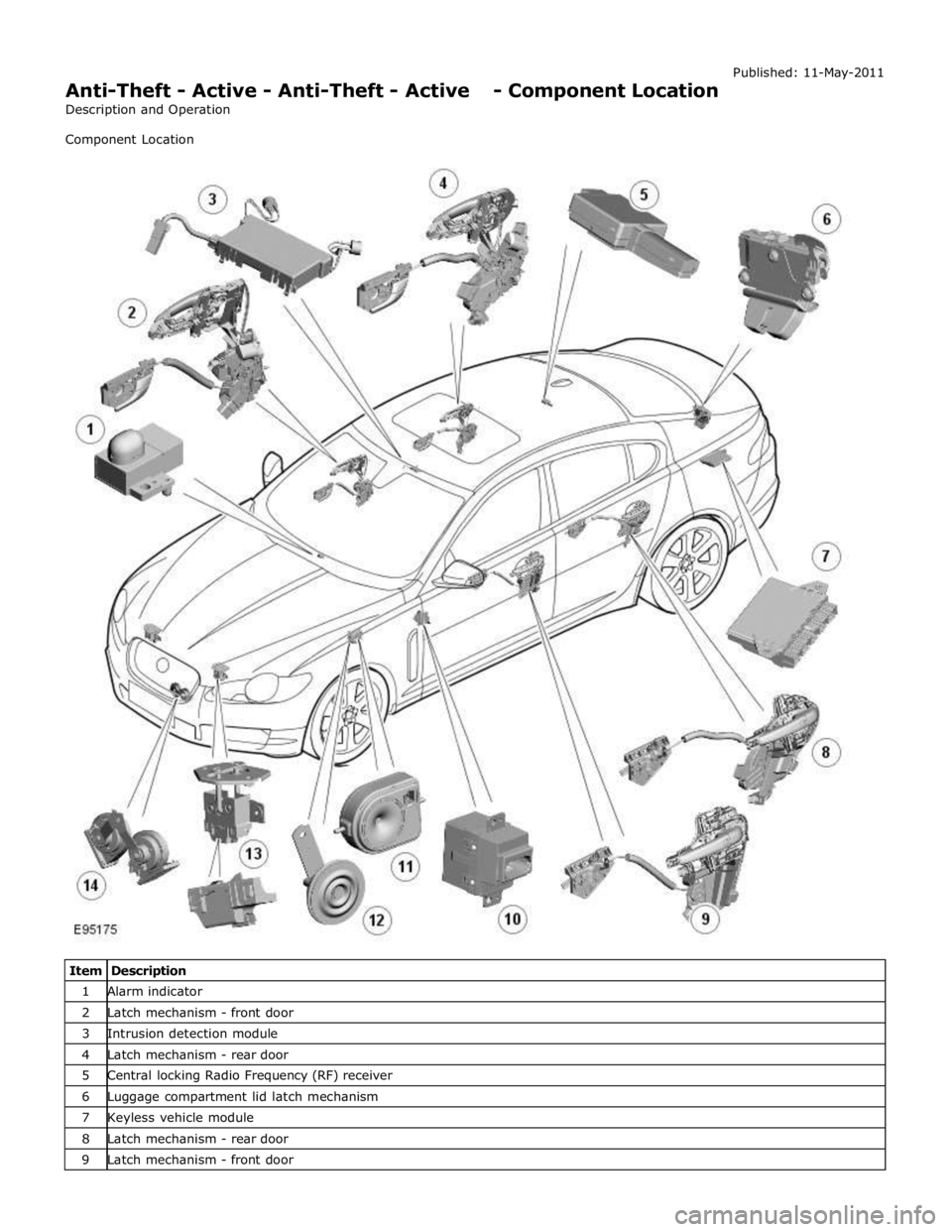
Anti-Theft - Active - Anti-Theft - Active - Component Location
Description and Operation
Component Location Published: 11-May-2011
Item Description 1 Alarm indicator 2 Latch mechanism - front door 3 Intrusion detection module 4 Latch mechanism - rear door 5 Central locking Radio Frequency (RF) receiver 6 Luggage compartment lid latch mechanism 7 Keyless vehicle module 8 Latch mechanism - rear door 9 Latch mechanism - front door
Page 2123 of 3039

7 Central locking - Radio Frequency (RF) receiver 8 Engine compartment lid - latch mechanism 9 Passive sounder 10 Battery backed sounder 11 Alarm indicator 12 Instrument cluster 13 Start control unit 14 Luggage compartment lid - latch mechanism 15 Door latch mechanism - LH (left-hand) rear 16 Door latch mechanism - RH (right-hand) rear 17 Door latch mechanism - RH front 18 Door latch mechanism - LH front 19 Door module - LH rear 20 Door module - RH rear 21 Door module - RH front 22 Door module - LH front 23 Intrusion detection module
Anti-Theft - Active System Operation
The active anti-theft system is available with three different levels of vehicle protection depending on market specification:
Hinged panel sensing
Hinged panel and intrusion sensing
Hinged panel, intrusion and inclination sensing.
The system is controlled by software in the CJB and RJB and indicates a trigger condition: Visually, using the direction indicators, and
Audibly, using the vehicle horn and either a passive or active sounder to indicate a trigger condition.
The passive sounder takes the form of an anti-theft disc horn located at the rear of the engine compartment on the LH side. The active sounder takes the form of a battery backed sounder located in the same position.
Depending on market specification, the battery backed sounder may be fitted with an inclination sensor. Both types of battery
backed sounder are visually identical and can only be identified by their part number. Both are also intelligent units, and
communicate to the CJB over a LIN (local interconnect network) bus connection.
Monitoring of the hinged panels is carried out using switches located in each door latch assembly, the engine-compartment-lid
latch assembly, and the luggage-compartment-lid latch assembly. The condition of the switches is monitored by the CJB.
Monitoring of front door lock status is carried out using switches located in the door latch mechanisms. The condition of the
switches is monitored by the front door modules and transmitted to the CJB over the medium speed CAN (controller area
network) bus.
Monitoring of the cabin interior is carried out using an intrusion detection module mounted behind the roof console. The
intrusion detection module comprises an ultrasonic sound wave sensor to determine if there is movement within the cabin.
Information from the intrusion detection module is communicated to the CJB over a LIN bus connection.
CAUTIONS:
The intrusion detection module electrical connections, particularly those to the sensors mounted in the roof console, are
very delicate and must be handled with care.
The intrusion detection module is an electro-statically sensitive part and should only be handled in an electro-statically
controlled environment.
When armed, the active anti-theft system can be triggered in one of the following ways:
A door ajar switch indicates a door has been opened.
The engine compartment lid or luggage compartment lid ajar switches indicate that either has been opened.
Either front door latch mechanism indicates a door has been unlocked.
The emergency key blade is used to open either the LH front door or luggage compartment.
The CJB or RJB are disconnected (this may result in only a partial trigger).
An attempt is made to start the engine without a valid signal from the Smart Key.
Refer to: Anti-Theft - Passive (419-01B Anti-Theft - Passive, Description and Operation).