2010 JAGUAR XFR crankshaft main
[x] Cancel search: crankshaft mainPage 15 of 3039

Catalyst Monitor Sensor RH
Crankshaft Position (CKP) Sensor
Engine Control Module (ECM)
Engine Coolant Temperature (ECT) Sensor
Engine Oil Level Sensor
Front Knock Sensor (KS) LH
Front Knock Sensor (KS) RH
Fuel Rail Pressure (FRP) Sensor
Heated Oxygen Sensor (HO2S) LH
Heated Oxygen Sensor (HO2S) RH
Manifold Absolute Pressure (MAP) Sensor
Mass Air Flow (MAF) Sensor
Rear Knock Sensor (KS) LH
Rear Knock Sensor (KS) RH
Variable Valve Timing (VVT) Oil Control Solenoid LH
Variable Valve Timing (VVT) Oil Control Solenoid RH307: Automatic Transmission/Transaxle
307-01B: Automatic Transmission/Transaxle - TDV6 3.0L Diesel /V8 5.0L Petrol/V8 S/C 5.0L
PetrolSpecificationDescription and OperationComponent Location
Overview
System Operation and Component DescriptionDiagnosis and TestingDiagnosticsGeneral ProceduresTransmission Fluid Level Check
Transmission Fluid Drain and RefillRemoval and InstallationInput Shaft Seal
Extension Housing Seal
Transmission Control Module (TCM) and Main Control Valve Body
Transmission Fluid Pan, Gasket and Filter
Transmission Support Insulator - V8 5.0L Petrol/V8 S/C 5.0L Petrol
Transmission, Transmission Fluid Cooler and Transmission Fluid Cooler Tubes - V8 5.0L Petrol/V8
S/C 5.0L Petrol
Transmission and Transmission Fluid Cooler - V8 5.0L Petrol/V8 S/C 5.0L PetrolRemovalTransmission - V8 5.0L Petrol/V8 S/C 5.0L PetrolInstallationTransmission - V8 5.0L Petrol/V8 S/C 5.0L Petrol
Page 852 of 3039
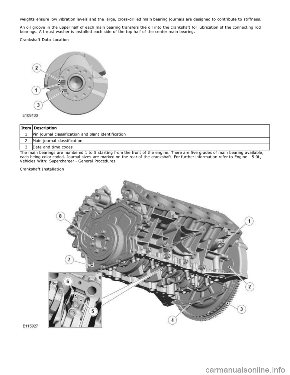
1 Pin journal classification and plant identification 2 Main journal classification 3 Date and time codes The main bearings are numbered 1 to 5 starting from the front of the engine. There are five grades of main bearing available,
each being color coded. Journal sizes are marked on the rear of the crankshaft. For further information refer to Engine - 5.0L,
Vehicles With: Supercharger - General Procedures.
Crankshaft Installation
Page 853 of 3039
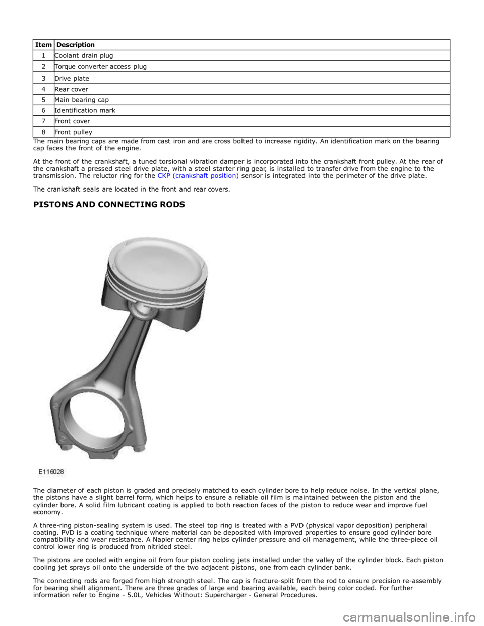
1 Coolant drain plug 2 Torque converter access plug 3 Drive plate 4 Rear cover 5 Main bearing cap 6 Identification mark 7 Front cover 8 Front pulley The main bearing caps are made from cast iron and are cross bolted to increase rigidity. An identification mark on the bearing
cap faces the front of the engine.
At the front of the crankshaft, a tuned torsional vibration damper is incorporated into the crankshaft front pulley. At the rear of
the crankshaft a pressed steel drive plate, with a steel starter ring gear, is installed to transfer drive from the engine to the
transmission. The reluctor ring for the CKP (crankshaft position) sensor is integrated into the perimeter of the drive plate.
The crankshaft seals are located in the front and rear covers.
PISTONS AND CONNECTING RODS
The diameter of each piston is graded and precisely matched to each cylinder bore to help reduce noise. In the vertical plane,
the pistons have a slight barrel form, which helps to ensure a reliable oil film is maintained between the piston and the
cylinder bore. A solid film lubricant coating is applied to both reaction faces of the piston to reduce wear and improve fuel
economy.
A three-ring piston-sealing system is used. The steel top ring is treated with a PVD (physical vapor deposition) peripheral
coating. PVD is a coating technique where material can be deposited with improved properties to ensure good cylinder bore
compatibility and wear resistance. A Napier center ring helps cylinder pressure and oil management, while the three-piece oil
control lower ring is produced from nitrided steel.
The pistons are cooled with engine oil from four piston cooling jets installed under the valley of the cylinder block. Each piston
cooling jet sprays oil onto the underside of the two adjacent pistons, one from each cylinder bank.
The connecting rods are forged from high strength steel. The cap is fracture-split from the rod to ensure precision re-assembly
for bearing shell alignment. There are three grades of large end bearing available, each being color coded. For further
information refer to Engine - 5.0L, Vehicles Without: Supercharger - General Procedures.
Page 858 of 3039
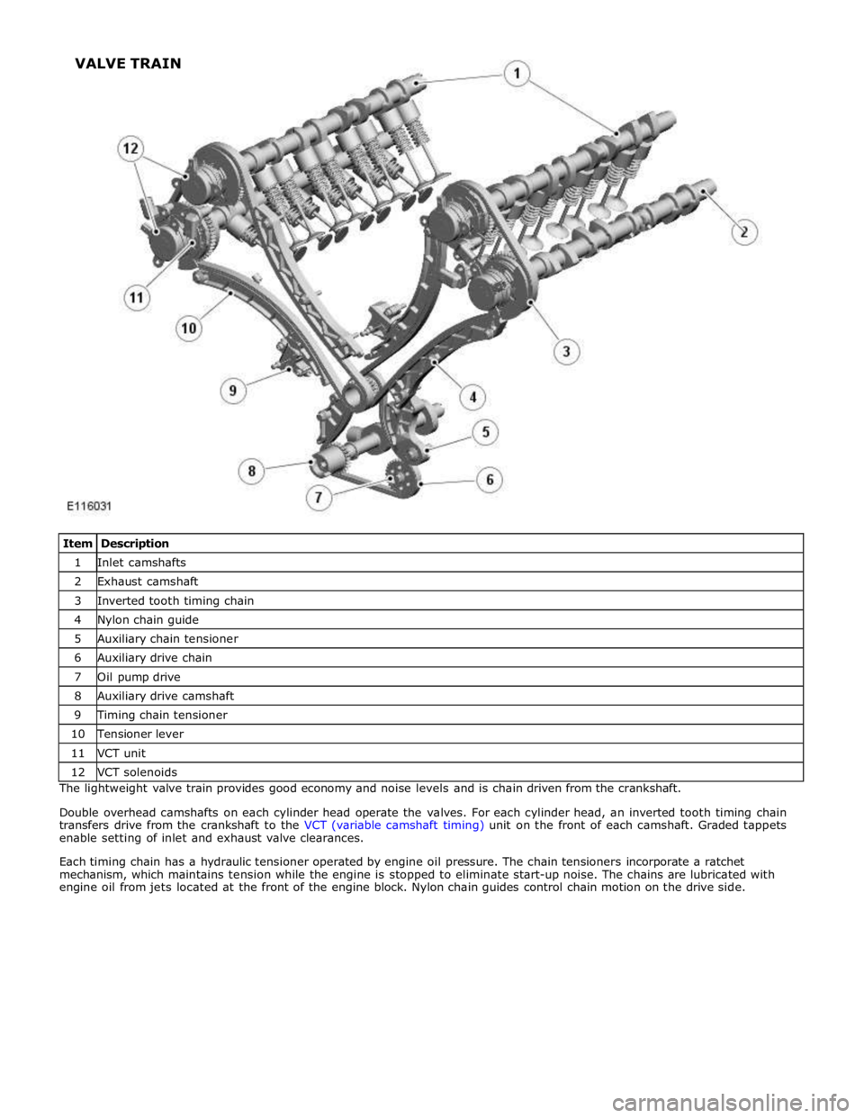
1 Inlet camshafts 2 Exhaust camshaft 3 Inverted tooth timing chain 4 Nylon chain guide 5 Auxiliary chain tensioner 6 Auxiliary drive chain 7 Oil pump drive 8 Auxiliary drive camshaft 9 Timing chain tensioner 10 Tensioner lever 11 VCT unit 12 VCT solenoids The lightweight valve train provides good economy and noise levels and is chain driven from the crankshaft.
Double overhead camshafts on each cylinder head operate the valves. For each cylinder head, an inverted tooth timing chain
transfers drive from the crankshaft to the VCT (variable camshaft timing) unit on the front of each camshaft. Graded tappets
enable setting of inlet and exhaust valve clearances.
Each timing chain has a hydraulic tensioner operated by engine oil pressure. The chain tensioners incorporate a ratchet
mechanism, which maintains tension while the engine is stopped to eliminate start-up noise. The chains are lubricated with
engine oil from jets located at the front of the engine block. Nylon chain guides control chain motion on the drive side. VALVE TRAIN
Page 899 of 3039

Engine - V8 S/C 5.0L Petrol - Valve Clearance Check
General Procedures
Check Published: 10-Jul-2013
1. Refer to: Battery Disconnect and Connect (414-01 Battery, Mounting and Cables, General Procedures).
2. WARNING: Do not work on or under a vehicle supported only by a jack.
Always support the vehicle on safety stands.
Raise and support the vehicle.
3. Refer to: Valve Cover LH (303-01D Engine - V8 S/C 5.0L Petrol, Removal and Installation).
4. Refer to: Valve Cover RH (303-01D Engine - V8 S/C 5.0L Petrol, Removal and Installation).
5. CAUTIONS:
Rotate the engine clockwise until the camshafts are positioned as
shown.
Do not rotate the crankshaft counterclockwise. The timing chains
may bind causing engine damage.
Camshaft lobes must be 180 degrees away from each valve tappet
or valve clearance will be incorrect.
NOTE: Using feeler gauge check the gap between the tappet and
the camshaft lobe and check against specifications table.
Using feeler gauge check the gap between the tappet and the
camshaft lobe and check against specifications table.
Repeat for the remaining valve tappets.
Page 1182 of 3039
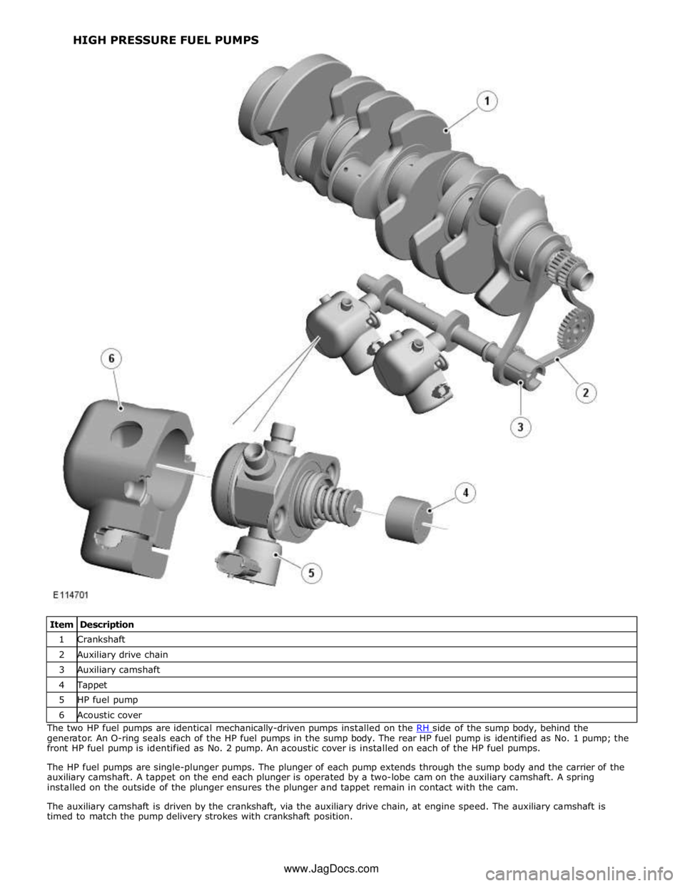
1 Crankshaft 2 Auxiliary drive chain 3 Auxiliary camshaft 4 Tappet 5 HP fuel pump 6 Acoustic cover The two HP fuel pumps are identical mechanically-driven pumps installed on the RH side of the sump body, behind the generator. An O-ring seals each of the HP fuel pumps in the sump body. The rear HP fuel pump is identified as No. 1 pump; the
front HP fuel pump is identified as No. 2 pump. An acoustic cover is installed on each of the HP fuel pumps.
The HP fuel pumps are single-plunger pumps. The plunger of each pump extends through the sump body and the carrier of the
auxiliary camshaft. A tappet on the end each plunger is operated by a two-lobe cam on the auxiliary camshaft. A spring
installed on the outside of the plunger ensures the plunger and tappet remain in contact with the cam.
The auxiliary camshaft is driven by the crankshaft, via the auxiliary drive chain, at engine speed. The auxiliary camshaft is
timed to match the pump delivery strokes with crankshaft position. HIGH PRESSURE FUEL PUMPS
www.JagDocs.com
Page 1249 of 3039
Published: 11-May-2011
Accessory Drive - V8 S/C 5.0L Petrol - Accessory Drive - Overview
Description and Operation
OVERVIEW
The accessory drive is a belt system powered by a pulley attached to the front of the crankshaft. The crankshaft pulley, which
incorporates a torsional vibration damper, drives two drive belts. An automatic belt tensioner in each belt run maintains the
drive belt at the correct tension. Together with idler pulleys, the belt tensioners also guide the drive belts clear of obstructions
and set the correct 'wrap-around' of the accessory component drive pulleys to ensure a slip-free drive.
PRIMARY DRIVE BELT
The primary drive belt is a six-ribbed poly-V belt that drives the:
Coolant pump
Power steering pump
A/C (air conditioning) compressor
Generator.
SECONDARY DRIVE BELT
The secondary drive belt is an eight-ribbed poly-V belt that drives the SC (supercharger).
BELT TENSIONERS
Each belt tensioner consists of an idler pulley on the end of a spring loaded pivot arm. The pivot arms can be turned manually
for removal and installation of the drive belts.
Each belt tensioners is calibrated to automatically maintain the correct tension in the related drive belt.
Page 1360 of 3039
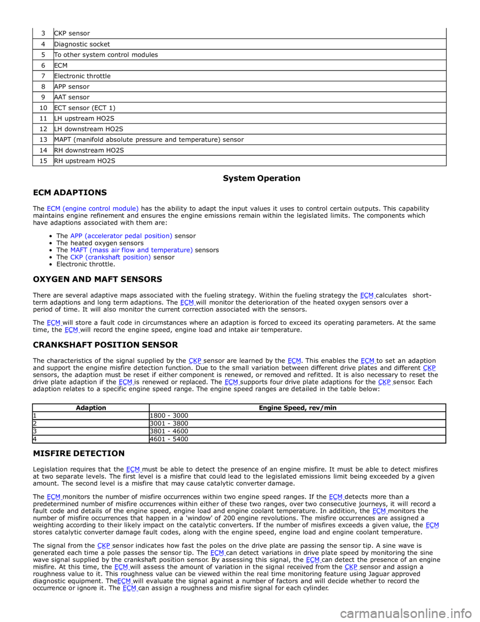
4 Diagnostic socket 5 To other system control modules 6 ECM 7 Electronic throttle 8 APP sensor 9 AAT sensor 10 ECT sensor (ECT 1) 11 LH upstream HO2S 12 LH downstream HO2S 13 MAPT (manifold absolute pressure and temperature) sensor 14 RH downstream HO2S 15 RH upstream HO2S
ECM ADAPTIONS System Operation
The ECM (engine control module) has the ability to adapt the input values it uses to control certain outputs. This capability
maintains engine refinement and ensures the engine emissions remain within the legislated limits. The components which
have adaptions associated with them are:
The APP (accelerator pedal position) sensor
The heated oxygen sensors
The MAFT (mass air flow and temperature) sensors
The CKP (crankshaft position) sensor
Electronic throttle.
OXYGEN AND MAFT SENSORS
There are several adaptive maps associated with the fueling strategy. Within the fueling strategy the ECM calculates short-term adaptions and long term adaptions. The ECM will monitor the deterioration of the heated oxygen sensors over a period of time. It will also monitor the current correction associated with the sensors.
The ECM will store a fault code in circumstances where an adaption is forced to exceed its operating parameters. At the same time, the ECM will record the engine speed, engine load and intake air temperature.
CRANKSHAFT POSITION SENSOR
The characteristics of the signal supplied by the CKP sensor are learned by the ECM. This enables the ECM to set an adaption and support the engine misfire detection function. Due to the small variation between different drive plates and different CKP sensors, the adaption must be reset if either component is renewed, or removed and refitted. It is also necessary to reset the
drive plate adaption if the ECM is renewed or replaced. The ECM supports four drive plate adaptions for the CKP sensor. Each adaption relates to a specific engine speed range. The engine speed ranges are detailed in the table below:
Adaption Engine Speed, rev/min 1 1800 - 3000 2 3001 - 3800 3 3801 - 4600 4 4601 - 5400 MISFIRE DETECTION
Legislation requires that the ECM must be able to detect the presence of an engine misfire. It must be able to detect misfires at two separate levels. The first level is a misfire that could lead to the legislated emissions limit being exceeded by a given
amount. The second level is a misfire that may cause catalytic converter damage.
The ECM monitors the number of misfire occurrences within two engine speed ranges. If the ECM detects more than a predetermined number of misfire occurrences within either of these two ranges, over two consecutive journeys, it will record a
fault code and details of the engine speed, engine load and engine coolant temperature. In addition, the ECM monitors the number of misfire occurrences that happen in a 'window' of 200 engine revolutions. The misfire occurrences are assigned a
weighting according to their likely impact on the catalytic converters. If the number of misfires exceeds a given value, the ECM stores catalytic converter damage fault codes, along with the engine speed, engine load and engine coolant temperature.
The signal from the CKP sensor indicates how fast the poles on the drive plate are passing the sensor tip. A sine wave is generated each time a pole passes the sensor tip. The ECM can detect variations in drive plate speed by monitoring the sine wave signal supplied by the crankshaft position sensor. By assessing this signal, the ECM can detect the presence of an engine misfire. At this time, the ECM will assess the amount of variation in the signal received from the CKP sensor and assign a roughness value to it. This roughness value can be viewed within the real time monitoring feature using Jaguar approved
diagnostic equipment. TheECM will evaluate the signal against a number of factors and will decide whether to record the occurrence or ignore it. The ECM can assign a roughness and misfire signal for each cylinder.