2010 JAGUAR XFR battery
[x] Cancel search: batteryPage 2 of 3039

Table of ContentsContents1: General Information
100: Service Information
100-00: General Information
Description and OperationAbout This Manual
Application and Use of Specifications
Battery and Battery Charging Health and Safety Precautions
Brake System Health and Safety Precautions
Diesel Fuel System Health and Safety Precautions
General Service Information
Health and Safety Precautions
How To Use This Manual
Important Safety Instructions
Petrol and Petrol-Ethanol Fuel Systems Health and Safety Precautions
Solvents, Sealants and Adhesives
Standard Workshop Practices
Symbols Glossary
Supplemental Restraint System (SRS) Health and Safety Precautions
Road/Roller Testing
Window Glass Health and Safety Precautions
Diagnostic Trouble Code (DTC) IndexDTC: Adaptive Damping Module (SUMB)
Diagnostic Trouble Code (DTC) IndexDTC: Anti-Lock Braking System (ABS)
Diagnostic Trouble Code (DTC) IndexDTC: Audio Amplifier Module (AAM)
Diagnostic Trouble Code (DTC) IndexDTC: Blind Spot Monitoring System Module (SODL/SODR)
Diagnostic Trouble Code (DTC) IndexDTC: Central Junction Box (CJB)
Diagnostic Trouble Code (DTC) IndexDTC: Climate Control Module (HVAC)
Diagnostic Trouble Code (DTC) IndexDTC: Digital Audio Broadcast Module (DABM)
Diagnostic Trouble Code (DTC) IndexDTC: Driver Door Module/Passenger Door Module (DDM/PDM)
Diagnostic Trouble Code (DTC) IndexDTC: Driver/Passenger Seat Module (DSM/PSM)
Diagnostic Trouble Code (DTC) IndexDTC: Electric Parking Brake (PBM)
Diagnostic Trouble Code (DTC) Index V8 S/C 5.0L Petrol, DTC: Engine Control Module (ECM)
Diagnostic Trouble Code (DTC) IndexDTC: Front Seat Climate Control Module (DCSM)
Diagnostic Trouble Code (DTC) IndexDTC: Headlamp Control Module (HCM)
Diagnostic Trouble Code (DTC) IndexDTC: Instrument Cluster (IPC)
Diagnostic Trouble Code (DTC) IndexDTC: Integrated Audio Module (IAM)
Diagnostic Trouble Code (DTC) IndexDTC: Integrated Control Panel (FCIMB)
Page 20 of 3039

Diagnosis and TestingInstrument ClusterRemoval and InstallationInstrument Cluster
Instrument Cluster Lens413-06: HornSpecificationRemoval and InstallationHorn
Horn Switch413-08: Information and Message Center
Description and OperationComponent Location
Overview
System Operation and Component DescriptionDiagnosis and TestingInformation and Message Center413-09: Warning Devices
Description and OperationComponent Location
Overview
System Operation and Component DescriptionDiagnosis and TestingWarning Devices413-13: Parking Aid
Description and OperationComponent Location
Overview
System Operation and Component DescriptionDiagnosis and TestingParking Aid
Proximity CameraRemoval and InstallationFront Inner Parking Aid Sensor
Front Outer Parking Aid Sensor
Parking Aid Camera
Parking Aid Module
Rear Parking Aid Sensor414: Battery and Charging System
414-00: Battery and Charging System - General Information
Description and OperationBattery Care Requirements
Page 21 of 3039

Quiescent Drain
Battery Report Form – In Service Batteries OnlyDiagnosis and TestingCharging System414-01: Battery, Mounting and CablesSpecificationDescription and OperationComponent Location
Overview
System Operation and Component DescriptionDiagnosis and TestingBatteryGeneral ProceduresBattery Disconnect and ConnectRemoval and InstallationBattery414-02C: Generator and Regulator - V8 5.0L Petrol/V8 S/C 5.0L PetrolSpecificationDescription and OperationComponent Location
Overview
System Operation and Component DescriptionRemoval and InstallationGenerator - V8 S/C 5.0L Petrol415: Information and Entertainment Systems
415-00: Information and Entertainment System - General Information
Description and OperationNavigation System Map UpdatesDiagnosis and TestingInformation and Entertainment System
Cellular Phone
Navigation System415-01A: Information and Entertainment SystemSpecification
Description and OperationAudio SystemComponent Location
Overview
System Operation and Component DescriptionSpeakersComponent Location
Overview
Page 45 of 3039

Published: 11-May-2011
General Information - Battery and Battery Charging Health and Safety Precautions
Description and Operation
WARNINGS:
Batteries contain sulphuric acid, avoid contact with skin, eyes or clothing. Wear safety goggles when working near the
battery to protect against possible splashing of the acid solution.
EYE CONTACT: If acid comes into contact with the eyes, flush immediately with plenty of running water for a minimum of
15 minutes. Seek immediate medical attention.
SKIN CONTACT: If acid comes into contact with the skin, flush immediately with plenty of running water for a minimum of
15 minutes. Seek immediate medical attention.
SWALLOWED: If acid is swallowed, rinse the mouth with plenty of water and then drink plenty of water or milk. Do not
induce vomiting. Seek immediate medical attention.
Batteries normally produce explosive gases. Do not allow naked flames, sparks or lighted substances to come near the
battery.
When charging the battery shield your face and wear safety goggles. Provide adequate ventilation.
CAUTION: Boost charging with excessive current or voltage above 16 volts will damage the battery.
www.JagDocs.com
Page 49 of 3039

General Information - General Service Information
Description and Operation
Repairs and Replacements Published: 28-Dec-2012
When service parts are required, it is essential that only genuine Jaguar/Daimler replacements are used.
Attention is drawn to the following points concerning repairs and the installation of replacement parts and accessories:
Safety features embodied in the vehicle may be impaired if other than genuine parts are installed. In certain territories,
legislation prohibits the installation of parts which are not produced to the vehicle manufacturer's specification.
Torque wrench setting figures given in this manual must be strictly adhered to. Locking devices, where specified, must
be installed. If the efficiency of a locking device is impaired during removal it must be renewed.
Owners purchasing accessories while travelling abroad should make sure that the accessory and its installed location on
the vehicle conform to mandatory requirements existing in their country of origin.
The vehicle warranty may be invalidated by the installation of other than genuine Jaguar/Daimler parts. All
Jaguar/Daimler replacements have the full backing of the factory warranty.
Jaguar/Daimler dealers are obliged to supply only genuine service parts.
Vehicle Specifications
Purchasers are advised that the specification details set out in this manual apply to a range of vehicles and not to any specific
one. For the specification of a particular vehicle, purchasers should consult their dealer.
The Manufacturer reserves the right to vary the specifications, with or without notice, and at such times and in such manner as
the Manufacturer thinks fit. Major as well as minor changes may be involved, in accordance with the Manufacturer's policy of
continuous improvement.
Whilst every effort is made to make sure the accuracy of the particulars contained in this manual, neither the Manufacturer nor
the Dealer, by whom the manual is supplied, shall in any circumstances be held liable for any inaccuracy or the consequences
thereof.
Service Repair Operation Numbering
A master index of numbered operations has been compiled for universal application to all vehicles manufactured by Jaguar
Land Rover Limited.
Each operation is allocated a number from the master index and cross-refers with an identical number in the Repair Operation
Times schedule. The number consists of six digits arranged in three pairs.
Each maintenance procedure in this manual is described in the sequence necessary to complete the operation in the minimum
time, as specified in the Repair Operation Times schedule.
References to Bank-1 and Bank-2
References to Bank-1 and Bank-2 are made with regard to the engine. When viewed from the flywheel the right-hand bank will
be Bank-1 and the left-hand bank will be Bank-2.
Special Tools
Any special tools and equipment required to perform a maintenance procedure, are shown at the beginning of each procedure.
When possible, illustrations are given to assist in identifying the tool needed.
Disconnecting/Connecting the Battery
Always stop the engine before disconnecting the battery negative lead and make sure the battery positive lead is isolated i.e.
wrapped in a suitable cloth.
WARNING: Radio code saving devices must not be used when conducting work on Air Bag or Fuel systems. It must be
noted that, when using these devices, the vehicle electrical system is still live albeit with a reduced current flow.
NOTE: Before disconnecting the battery make sure that the radio receiver/cassette player/mini disc player and compact
disc player keycodes are known and, that no data is required from the Engine Control Module (ECM) as battery disconnection
will erase any fault codes and idle/drive values held in the Keep Alive Memory (KAM).
Always disconnect the battery before commencing repair operations which require:
The vehicle to be jacked up
Work on the engine
Work underneath the vehicle
Arc welding
Alternatively a Radio Code Saver may be used, when not working on the Air Bag or Fuel systems. With the battery
Page 50 of 3039

disconnected, a Radio Code Saver will allow sufficient current to pass to maintain the radio receiver/cassette player/mini disc
player and compact disc player memory, operate the clock and supply the door operated interior lights while isolating the
battery in the event of a short circuit.
Reconnecting the Battery
WARNING: If the battery has been on bench charge the cells may be giving off explosive hydrogen gas. Avoid creating
sparks, and if in doubt cover the vent plugs or covers with a damp cloth.
Always make sure that all electrical systems are switched OFF before reconnecting the battery to avoid causing sparks or
damage to sensitive electrical equipment.
Always reconnect the battery positive lead first and the negative last, ensuring that there is a good electrical contact and the
battery terminals are secure.
Restart the clock (where installed) and set it to the correct time.
Enter the radio receiver/cassette player/mini disc player and compact disc player keycodes and preset' frequencies, if known.
Following reconnection of the battery, the engine should be allowed to idle until it has reached normal operating temperature
as the stored idle and drive values contained within the ECM have been lost. Allow the vehicle to idle for a further three
minutes. Drive the vehicle at constant speeds of approximately 48 km/h (30 mph), 64 km/h (40 mph), 80 km/h (50 mph), 96
km/h (60 mph) and 112 km/h (70 mph) for three minutes each. This will allow the ECM to relearn idle and drive values, and
may cause driveability concerns if the procedure is not carried out.
Connecting a Slave Battery Using Jump Leads
WARNING: If the slave battery has recently been charged and is gassing, cover the vent plugs or covers with a damp
cloth to reduce the risk of explosion should arcing occur when connecting the jump leads.
CAUTIONS:
A discharged battery condition may have been caused by an electrical short circuit. If this condition exists there will be
an apparently live circuit on the vehicle even when all circuits are switched off. This can cause arcing when the jump leads are
connected.
Whilst it is not recommended that the vehicle is jump started, it is recognized that this may occasionally be the only
practical way to mobilize a vehicle. In such an instance the discharged battery must be recharged immediately after jump
starting to avoid permanent damage.
Always make sure that the jump leads are adequate for the task. Heavy duty cables must be used.
Always make sure that the slave battery is of the same voltage as the vehicle battery. The batteries must be connected
in parallel.
Always make sure that switchable electric circuits are switched off before connecting jump leads. This reduces the risk
of sparks occurring when the final connection is made.
WARNING: Make sure that the ends of the jump leads do not touch each other or ground against the vehicle body at any
time while the leads are attached to the battery. A fully charged battery, if shorted through jump leads, can discharge at a rate
well above 1000 amps causing violent arcing and very rapid heating of the jump leads and terminals, and can even cause the
battery to explode.
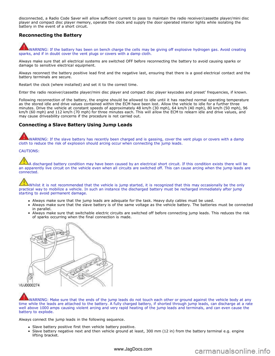
Always connect the jump leads in the following sequence.
Slave battery positive first then vehicle battery positive.
Slave battery negative next and then vehicle ground at least, 300 mm (12 in) from the battery terminal e.g. engine
lifting bracket. www.JagDocs.com
Page 51 of 3039

Always reduce the engine speed to idle before disconnecting the jump leads.
Before removing the jump leads, switch on the heater blower (high) or the heated rear screen, to reduce the voltage peak
when the leads are removed.
Always disconnect the jump leads in the reverse order to the connecting sequence and take great care not to short the ends of
the leads.
Do not rely on the generator to restore a discharged battery. For a generator to recharge a battery, it would take in excess of 8
hours continuous driving with no additional loads placed on the battery.
Component Cleaning
To prevent ingress of dirt, accumulations of loose dirt and greasy deposits should be removed before disconnecting or
dismantling components or assemblies.
Components should be thoroughly cleaned before inspection prior to reassembly.
Cleaning Methods:
Dry Cleaning
Removal of loose dirt with soft or wire brushes
Scraping dirt off with a piece of metal or wood
Wiping off with a rag
CAUTION: Compressed air is sometimes wet so use with caution, especially on hydraulic systems.
Blowing dirt off with compressed air (Eye protection should be worn when using this method)
Removal of dry dust using vacuum equipment. This method should always be used to remove friction lining material
dust (asbestos particles)
Steam Cleaning
Calibration of Essential Measuring Equipment
WARNING: Failure to comply may result in personal injury or damage to components.
It is of fundamental importance that certain essential equipment e.g. torque wrenches, multimeters, exhaust gas analysers,
rolling roads etc., are regularly calibrated in accordance with the manufacturers instructions.
Use of Control Modules
Control modules may only be used on the vehicle to which they were originally installed. Do not attempt to use or test a
control module on any other vehicle.
Functional Test
On completion of a maintenance procedure, a thorough test should be carried out, to ensure the relevant vehicle systems are
working correctly.
Preparation
Before disassembly, clean the surrounding area as thoroughly as possible. When components have been removed, blank off
any exposed openings using grease-proof paper and masking tape. Immediately seal fuel, oil and hydraulic lines when
separated, using plastic caps or plugs, to prevent loss of fluid and the entry of dirt. Close the open ends of oil ways, exposed
by component removal, with tapered hardwood plugs or readily visible plastic plugs. Immediately a component is removed,
place it in a suitable container; use a separate container for each component and its associated parts. Before dismantling a
component, clean it thoroughly with a recommended cleaning agent; check that the agent will not damage any of the materials
within the component. Clean the bench and obtain marking materials, labels, containers and locking wire before dismantling a
component.
Dismantling
Observe scrupulous cleanliness when dismantling components, particularly when parts of the brake, fuel or hydraulic systems
are being worked on. A particle of dirt or a fragment of cloth could cause a dangerous malfunction if trapped in these systems.
Clean all tapped holes, crevices, oil ways and fluid passages with compressed air.
WARNING: Do not permit compressed air to enter an open wound. Always use eye protection when using compressed air.
Make sure that any O-rings used for sealing are correctly reinstalled or renewed if disturbed. Mark mating parts to make sure
that they are replaced as dismantled. Whenever possible use marking materials which avoid the possibilities of causing
distortion or the initiation of cracks, which could occur if a center punch or scriber were used. Wire together mating parts where
necessary to prevent accidental interchange (e.g roller bearing components). Tie labels on to all parts to be renewed and to
parts requiring further inspection before being passed for reassembly. Place labelled parts and other parts for rebuild in
separate containers. Do not discard a part which is due for renewal until it has been compared with the new part, to make sure
Page 52 of 3039

Air Conditioning A/C Accelerator Pedal Position APP
Is a multitrack sensor which inputs the drivers demand into the engine
control module (ECM) After Bottom Dead Center ABDC Event occurring after bottom dead center After Top Dead Center ATDC Event occurring after top dead center Anti-lock Brake System ABS
System which prevents wheel lock-up under braking by sensing lack of
rotation of a wheel(s) and diverting fluid pressure away from it (them) Alternating Current ac Amplitude Modulation AM Automatic Temperature Control ATC Automatic Transmission Fluid ATF Ampere A SI unit of current Ampere hour Ah Barometric Pressure BARO Pressure of surrounding air at any given temperature and altitude Battery positive voltage B+ The positive voltage from a battery or any circuit connected directly to it Before Bottom Dead Center BBDC Event occurring before bottom dead center Before Top Dead Center BTDC Event occurring before top dead center Bottom Dead Center BDC Lowest point of piston travel in a reciprocating engine Battery Junction Box BJB Brake Pedal Position BPP Brake Horsepower BHP
Effective horsepower developed by an engine or motor, as measured by a
brake applied to its output shaft British Standard BS Standard specification issued by the British Standards Institution Brake Traction Control System BTCS