Page 693 of 3039
Published: 11-May-2011
Anti-Lock Control - Stability Assist - Anti-Lock Control - Stability Assist - System Operation and Component Description
Description and Operation
Control Diagram
NOTE: A = Hardwired; D = High speed CAN (controller area network) bus; N = Medium speed CANCAN bus; V = Private CAN bus.
Item Description 1 Battery 2 BJB (battery junction box) (250 A megafuse) 3 CJB (central junction box) 4 EJB (engine junction box) 5 LH (left-hand) front wheel speed sensor
Page 778 of 3039
Published: 20-May-2014
Steering Column - Steering Column - System Operation and Component Description
Description and Operation
Control Diagram
NOTE: A = Hardwired; D = High speed CAN bus; N = Medium speed CAN bus
Item Description 1 Battery 2 BJB (battery junction box) - Megafuse (175A) 3 RJB (rear junction box) 4 Electric steering column lock 5 High Speed CAN (controller area network) bus to other vehicle systems 6 CJB (central junction box)
Page 804 of 3039

Steering Column Switches - Steering Column Switches
Diagnosis and Testing
Principle of Operation Published: 14-Jul-2014
For a detailed description of the steering column lock and switches, refer to the relevant Description and Operation section in
the workshop manual. REFER to: (211-05 Steering Column Switches)
Steering Column Switches (Description and Operation), Steering Column Switches (Description and Operation), Steering Column Switches (Description and Operation).
Inspection and Verification
CAUTION: Diagnosis by substitution from a donor vehicle is NOT acceptable. Substitution of control modules does not
guarantee confirmation of a fault, and may also cause additional faults in the vehicle being tested and/or the donor vehicle.
1. Verify the customer concern.
2. Visually inspect for obvious signs of damage and system integrity.
Visual Inspection
Mechanical Electrical
Switches
Steering column lock
Fuse(s)
Electrical connector(s)
Wiring Harness
3. If an obvious cause for an observed or reported concern is found, correct the cause (if possible) before proceeding to
the next step.
4. If the cause is not visually evident, check for DTCs and refer to the DTC Index.
DTC Index
For a list of Diagnostic Trouble Codes (DTCs) that could be logged on this vehicle, please refer to Section 100-00.
REFER to: Diagnostic Trouble Code (DTC) Index - DTC: Central Junction Box (CJB) (100-00 General Information, Description and Operation).
Page 1112 of 3039
Published: 11-May-2011
Engine Cooling - V8 5.0L Petrol/V8 S/C 5.0L Petrol - Engine Cooling - System
Operation and Component Description
Description and Operation
Control Diagram
NOTE: A = Hardwired
Item Description 1 Battery 2 BJB (battery junction box) (250 A megafuse) 3 EJB (engine junction box) 4 Cooling fan 5 ECM (engine control module) www.JagDocs.com
Page 1124 of 3039

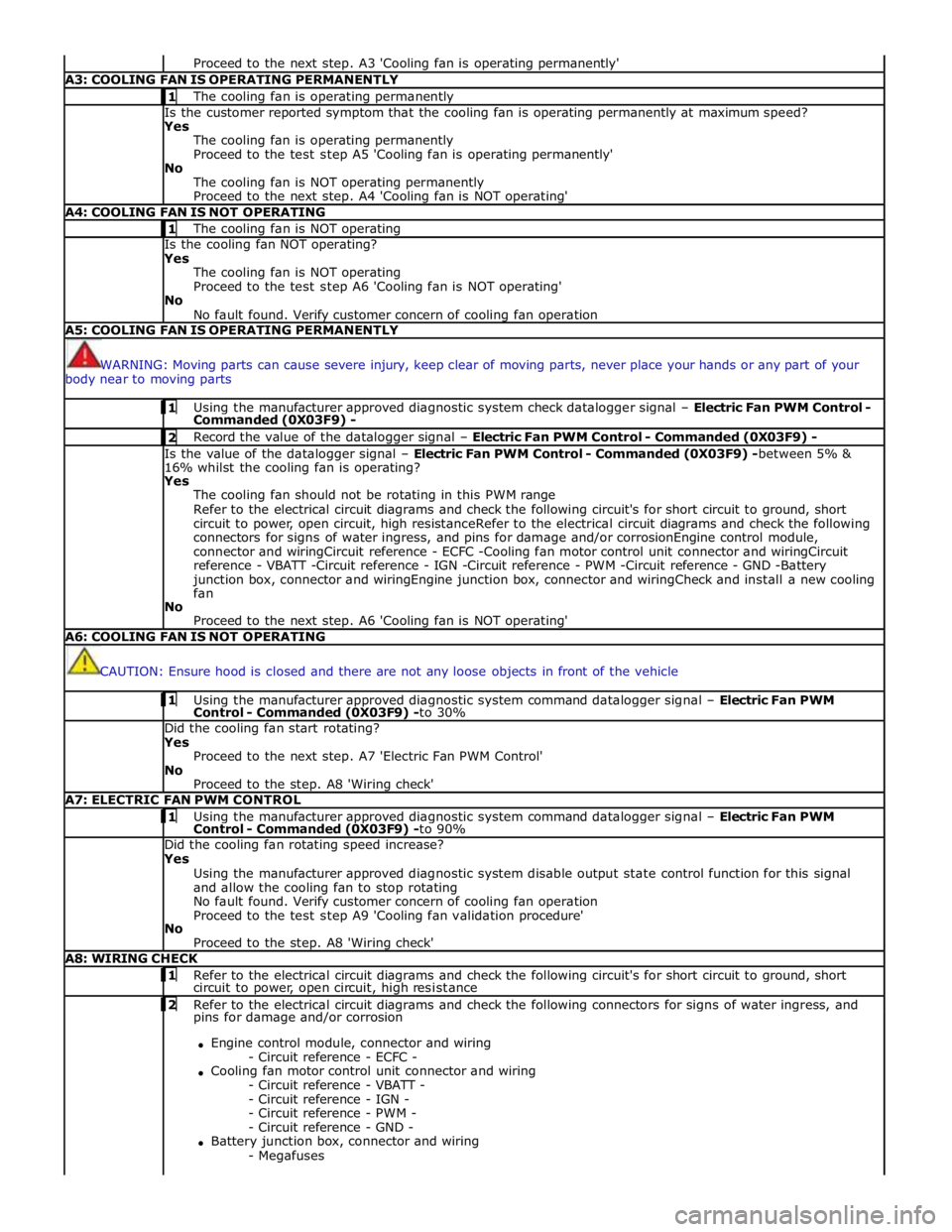
Proceed to the next step. A3 'Cooling fan is operating permanently' A3: COOLING FAN IS OPERATING PERMANENTLY 1 The cooling fan is operating permanently Is the customer reported symptom that the cooling fan is operating permanently at maximum speed?
Yes
The cooling fan is operating permanently
Proceed to the test step A5 'Cooling fan is operating permanently'
No
The cooling fan is NOT operating permanently
Proceed to the next step. A4 'Cooling fan is NOT operating' A4: COOLING FAN IS NOT OPERATING 1 The cooling fan is NOT operating Is the cooling fan NOT operating?
Yes
The cooling fan is NOT operating
Proceed to the test step A6 'Cooling fan is NOT operating'
No
No fault found. Verify customer concern of cooling fan operation A5: COOLING FAN IS OPERATING PERMANENTLY
WARNING: Moving parts can cause severe injury, keep clear of moving parts, never place your hands or any part of your
body near to moving parts 1 Using the manufacturer approved diagnostic system check datalogger signal – Electric Fan PWM Control - Commanded (0X03F9) - 2 Record the value of the datalogger signal – Electric Fan PWM Control - Commanded (0X03F9) - Is the value of the datalogger signal – Electric Fan PWM Control - Commanded (0X03F9) -between 5% &
16% whilst the cooling fan is operating?
Yes
The cooling fan should not be rotating in this PWM range
Refer to the electrical circuit diagrams and check the following circuit's for short circuit to ground, short
circuit to power, open circuit, high resistanceRefer to the electrical circuit diagrams and check the following
connectors for signs of water ingress, and pins for damage and/or corrosionEngine control module,
connector and wiringCircuit reference - ECFC -Cooling fan motor control unit connector and wiringCircuit
reference - VBATT -Circuit reference - IGN -Circuit reference - PWM -Circuit reference - GND -Battery
junction box, connector and wiringEngine junction box, connector and wiringCheck and install a new cooling
fan
No
Proceed to the next step. A6 'Cooling fan is NOT operating' A6: COOLING FAN IS NOT OPERATING
CAUTION: Ensure hood is closed and there are not any loose objects in front of the vehicle 1 Using the manufacturer approved diagnostic system command datalogger signal – Electric Fan PWM Control - Commanded (0X03F9) -to 30% Did the cooling fan start rotating?
Yes
Proceed to the next step. A7 'Electric Fan PWM Control'
No
Proceed to the step. A8 'Wiring check' A7: ELECTRIC FAN PWM CONTROL 1 Using the manufacturer approved diagnostic system command datalogger signal – Electric Fan PWM Control - Commanded (0X03F9) -to 90% Did the cooling fan rotating speed increase?
Yes
Using the manufacturer approved diagnostic system disable output state control function for this signal
and allow the cooling fan to stop rotating
No fault found. Verify customer concern of cooling fan operation
Proceed to the test step A9 'Cooling fan validation procedure'
No
Proceed to the step. A8 'Wiring check' A8: WIRING CHECK 1 Refer to the electrical circuit diagrams and check the following circuit's for short circuit to ground, short circuit to power, open circuit, high resistance 2 Refer to the electrical circuit diagrams and check the following connectors for signs of water ingress, and pins for damage and/or corrosion
Engine control module, connector and wiring
- Circuit reference - ECFC -
Cooling fan motor control unit connector and wiring
- Circuit reference - VBATT -
- Circuit reference - IGN -
- Circuit reference - PWM -
- Circuit reference - GND -
Battery junction box, connector and wiring
- Megafuses
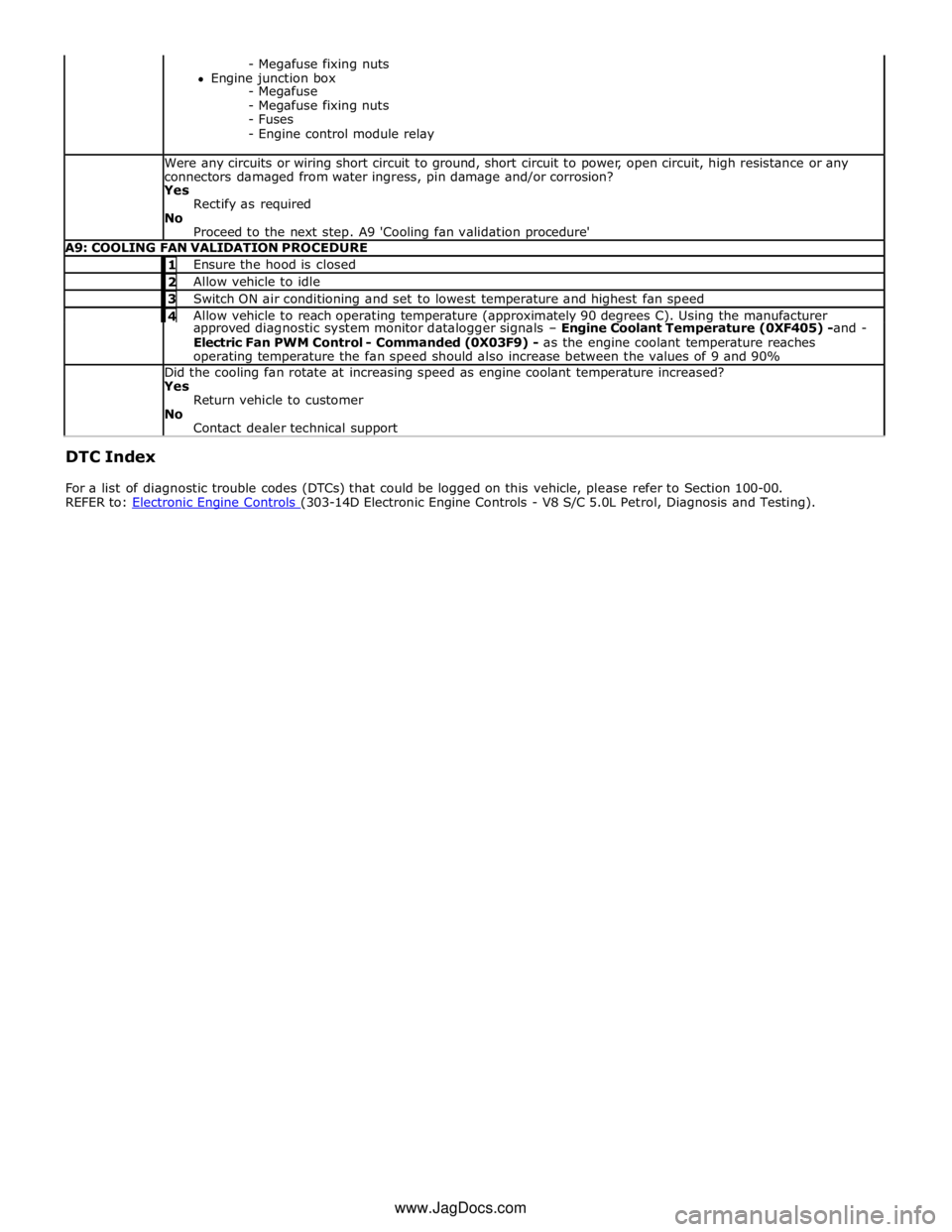
Page 1125 of 3039

- Megafuse fixing nuts
Engine junction box
- Megafuse
- Megafuse fixing nuts
- Fuses
- Engine control module relay Were any circuits or wiring short circuit to ground, short circuit to power, open circuit, high resistance or any
connectors damaged from water ingress, pin damage and/or corrosion?
Yes
Rectify as required
No
Proceed to the next step. A9 'Cooling fan validation procedure' A9: COOLING FAN VALIDATION PROCEDURE 1 Ensure the hood is closed 2 Allow vehicle to idle 3 Switch ON air conditioning and set to lowest temperature and highest fan speed 4 Allow vehicle to reach operating temperature (approximately 90 degrees C). Using the manufacturer approved diagnostic system monitor datalogger signals – Engine Coolant Temperature (0XF405) -and -
Electric Fan PWM Control - Commanded (0X03F9) - as the engine coolant temperature reaches
operating temperature the fan speed should also increase between the values of 9 and 90% Did the cooling fan rotate at increasing speed as engine coolant temperature increased?
Yes
Return vehicle to customer
No
Contact dealer technical support DTC Index
For a list of diagnostic trouble codes (DTCs) that could be logged on this vehicle, please refer to Section 100-00.
REFER to: Electronic Engine Controls (303-14D Electronic Engine Controls - V8 S/C 5.0L Petrol, Diagnosis and Testing). www.JagDocs.com
Page 1169 of 3039
Published: 11-May-2011
Supercharger Cooling - V8 S/C 5.0L Petrol - Supercharger Cooling - System
Operation and Component Description
Description and Operation
Control Diagram
NOTE: A = Hardwired
Item Description 1 Battery 2 BJB (battery junction box) (250 A megafuse) 3 EJB (engine junction box) 4 Charge air coolant pump 5 ECM (engine control module)
Page 1180 of 3039
Published: 15-Mar-2013
Fuel Charging and Controls - V8 S/C 5.0L Petrol - Fuel Charging and Controls
- System Operation and Component Description
Description and Operation
Control Diagram
NOTE: A = Hardwired
Item Description 1 Battery 2 BJB (battery junction box) (250 A megafuse) 3 EJB (engine junction box) 4 No. 1 HP fuel pump 5 No. 2 HP fuel pump 6 Fuel injectors 7 ECM 8 FRP sensor