2010 JAGUAR XFR length
[x] Cancel search: lengthPage 2684 of 3039
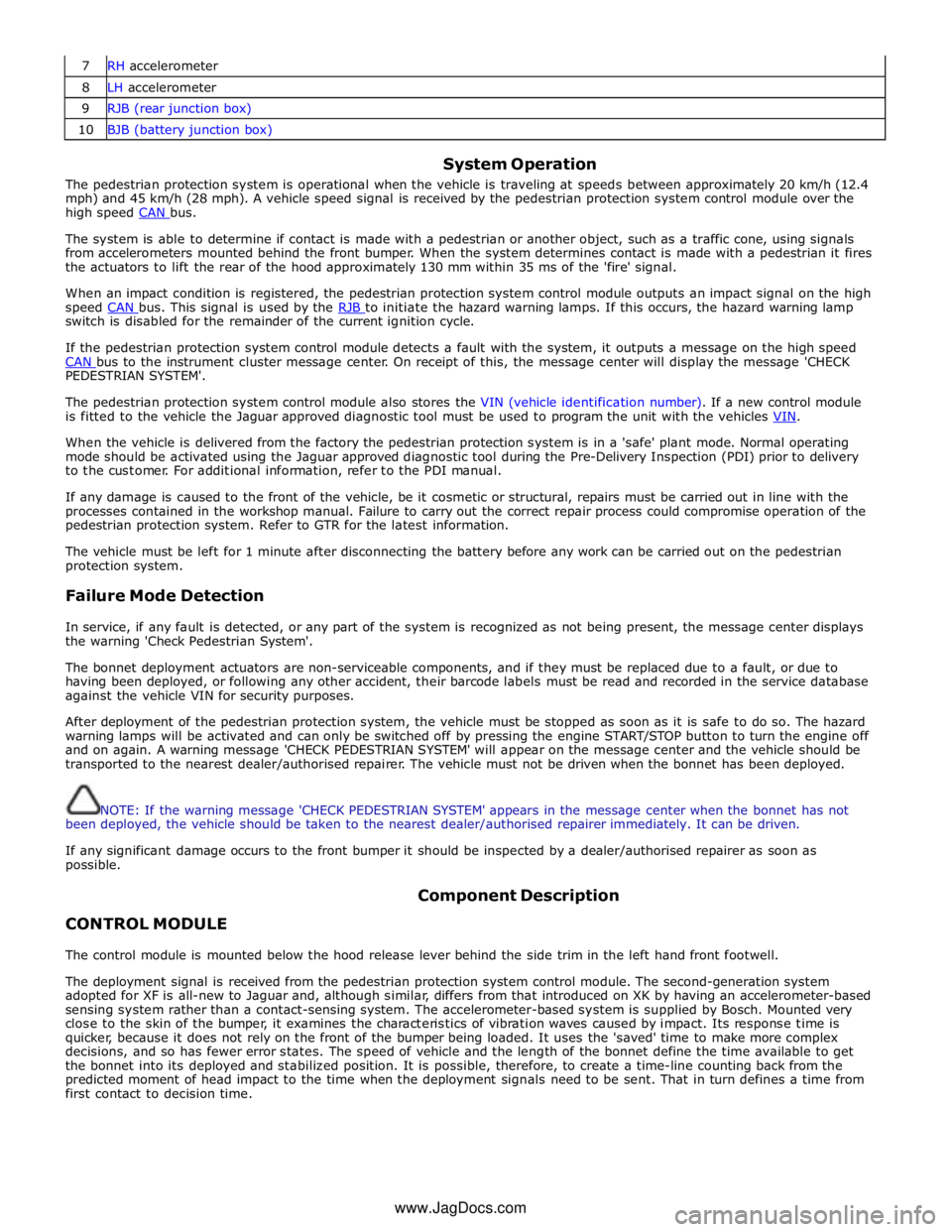
7 RH accelerometer 8 LH accelerometer 9 RJB (rear junction box) 10 BJB (battery junction box)
System Operation
The pedestrian protection system is operational when the vehicle is traveling at speeds between approximately 20 km/h (12.4
mph) and 45 km/h (28 mph). A vehicle speed signal is received by the pedestrian protection system control module over the
high speed CAN bus.
The system is able to determine if contact is made with a pedestrian or another object, such as a traffic cone, using signals
from accelerometers mounted behind the front bumper. When the system determines contact is made with a pedestrian it fires
the actuators to lift the rear of the hood approximately 130 mm within 35 ms of the 'fire' signal.
When an impact condition is registered, the pedestrian protection system control module outputs an impact signal on the high
speed CAN bus. This signal is used by the RJB to initiate the hazard warning lamps. If this occurs, the hazard warning lamp switch is disabled for the remainder of the current ignition cycle.
If the pedestrian protection system control module detects a fault with the system, it outputs a message on the high speed
CAN bus to the instrument cluster message center. On receipt of this, the message center will display the message 'CHECK PEDESTRIAN SYSTEM'.
The pedestrian protection system control module also stores the VIN (vehicle identification number). If a new control module
is fitted to the vehicle the Jaguar approved diagnostic tool must be used to program the unit with the vehicles VIN.
When the vehicle is delivered from the factory the pedestrian protection system is in a 'safe' plant mode. Normal operating
mode should be activated using the Jaguar approved diagnostic tool during the Pre-Delivery Inspection (PDI) prior to delivery
to the customer. For additional information, refer to the PDI manual.
If any damage is caused to the front of the vehicle, be it cosmetic or structural, repairs must be carried out in line with the
processes contained in the workshop manual. Failure to carry out the correct repair process could compromise operation of the
pedestrian protection system. Refer to GTR for the latest information.
The vehicle must be left for 1 minute after disconnecting the battery before any work can be carried out on the pedestrian
protection system.
Failure Mode Detection
In service, if any fault is detected, or any part of the system is recognized as not being present, the message center displays
the warning 'Check Pedestrian System'.
The bonnet deployment actuators are non-serviceable components, and if they must be replaced due to a fault, or due to
having been deployed, or following any other accident, their barcode labels must be read and recorded in the service database
against the vehicle VIN for security purposes.
After deployment of the pedestrian protection system, the vehicle must be stopped as soon as it is safe to do so. The hazard
warning lamps will be activated and can only be switched off by pressing the engine START/STOP button to turn the engine off
and on again. A warning message 'CHECK PEDESTRIAN SYSTEM' will appear on the message center and the vehicle should be
transported to the nearest dealer/authorised repairer. The vehicle must not be driven when the bonnet has been deployed.
NOTE: If the warning message 'CHECK PEDESTRIAN SYSTEM' appears in the message center when the bonnet has not
been deployed, the vehicle should be taken to the nearest dealer/authorised repairer immediately. It can be driven.
If any significant damage occurs to the front bumper it should be inspected by a dealer/authorised repairer as soon as
possible.
CONTROL MODULE Component Description
The control module is mounted below the hood release lever behind the side trim in the left hand front footwell.
The deployment signal is received from the pedestrian protection system control module. The second-generation system
adopted for XF is all-new to Jaguar and, although similar, differs from that introduced on XK by having an accelerometer-based
sensing system rather than a contact-sensing system. The accelerometer-based system is supplied by Bosch. Mounted very
close to the skin of the bumper, it examines the characteristics of vibration waves caused by impact. Its response time is
quicker, because it does not rely on the front of the bumper being loaded. It uses the 'saved' time to make more complex
decisions, and so has fewer error states. The speed of vehicle and the length of the bonnet define the time available to get
the bonnet into its deployed and stabilized position. It is possible, therefore, to create a time-line counting back from the
predicted moment of head impact to the time when the deployment signals need to be sent. That in turn defines a time from
first contact to decision time.
www.JagDocs.com
Page 2707 of 3039
For instance, the crumple zones absorb the bulk of the impact energy. If any unprofessional repair techniques or
methods are used in these areas then this can pose a fundamental threat to vehicle safety.
Hidden damage
As well as looking at external indicators like flaked off paint, it is vital to check for hidden body damage or deformation
that is not visible from the outside. Large attached parts like bumpers and inner fenders often need to be removed to
allow accurate assessment of damage to underlying body parts.
Gap dimensions
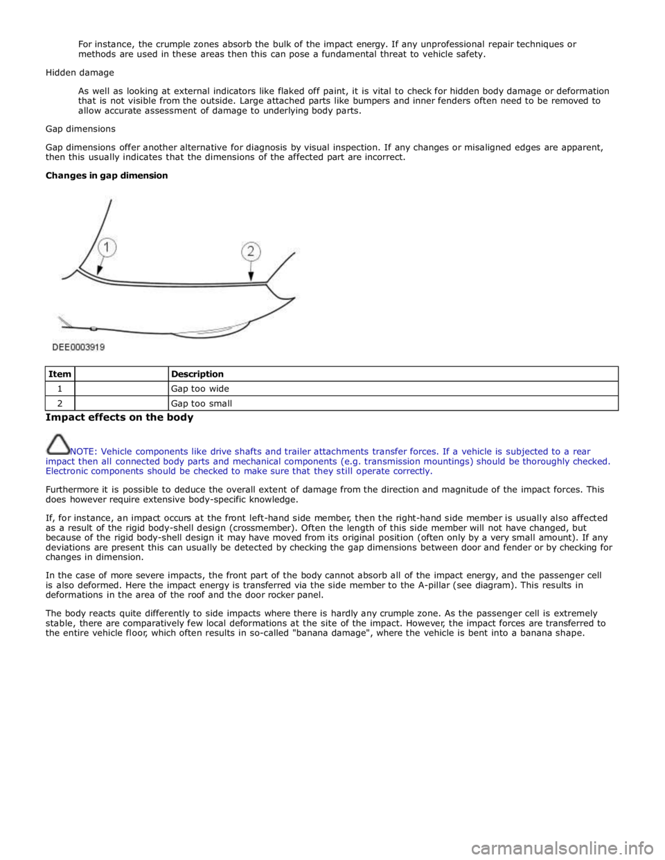
Gap dimensions offer another alternative for diagnosis by visual inspection. If any changes or misaligned edges are apparent,
then this usually indicates that the dimensions of the affected part are incorrect.
Changes in gap dimension
Item
Description 1
Gap too wide 2
Gap too small Impact effects on the body
NOTE: Vehicle components like drive shafts and trailer attachments transfer forces. If a vehicle is subjected to a rear
impact then all connected body parts and mechanical components (e.g. transmission mountings) should be thoroughly checked.
Electronic components should be checked to make sure that they still operate correctly.
Furthermore it is possible to deduce the overall extent of damage from the direction and magnitude of the impact forces. This
does however require extensive body-specific knowledge.
If, for instance, an impact occurs at the front left-hand side member, then the right-hand side member is usually also affected
as a result of the rigid body-shell design (crossmember). Often the length of this side member will not have changed, but
because of the rigid body-shell design it may have moved from its original position (often only by a very small amount). If any
deviations are present this can usually be detected by checking the gap dimensions between door and fender or by checking for
changes in dimension.
In the case of more severe impacts, the front part of the body cannot absorb all of the impact energy, and the passenger cell
is also deformed. Here the impact energy is transferred via the side member to the A-pillar (see diagram). This results in
deformations in the area of the roof and the door rocker panel.
The body reacts quite differently to side impacts where there is hardly any crumple zone. As the passenger cell is extremely
stable, there are comparatively few local deformations at the site of the impact. However, the impact forces are transferred to
the entire vehicle floor, which often results in so-called "banana damage", where the vehicle is bent into a banana shape.
Page 2708 of 3039
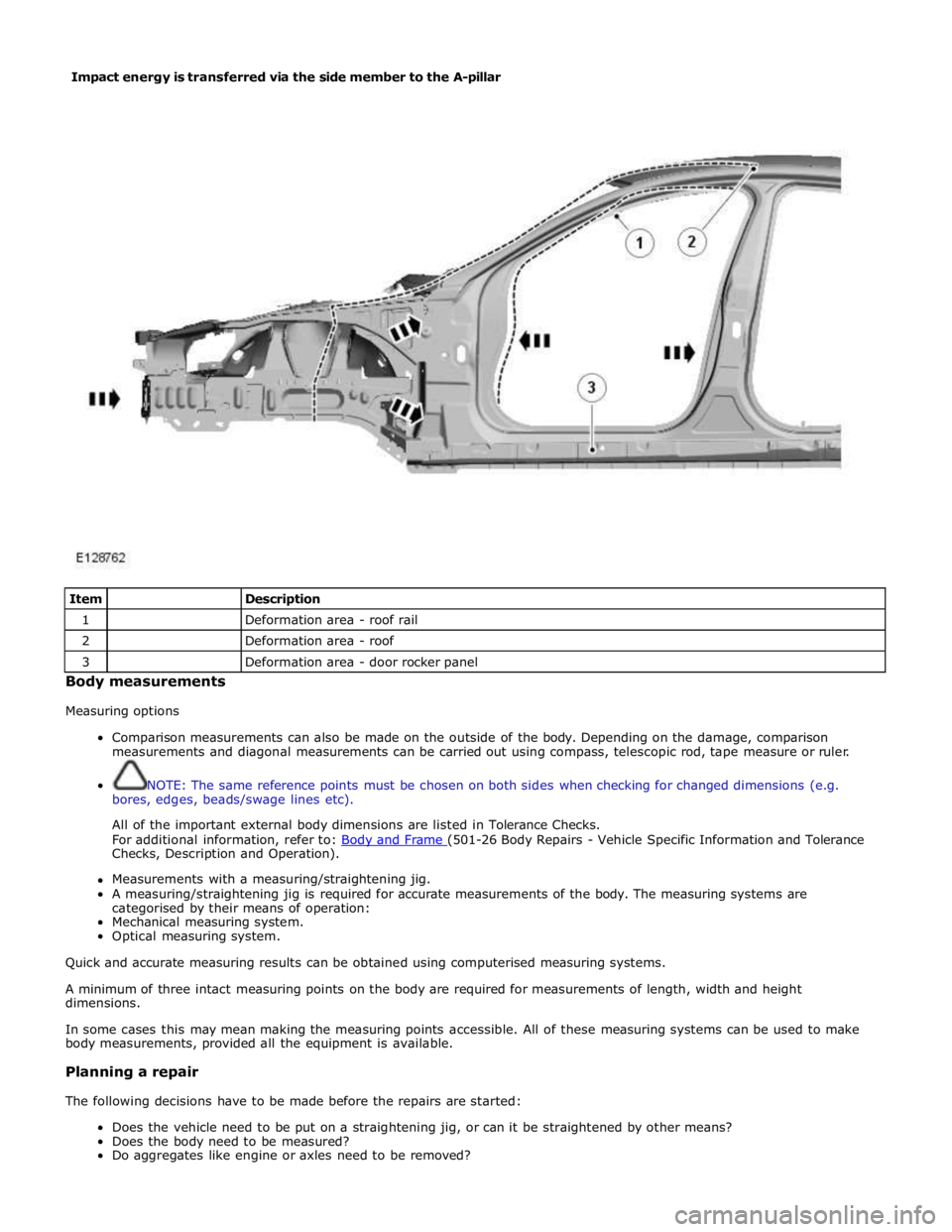
Item
Description 1
Deformation area - roof rail 2
Deformation area - roof 3
Deformation area - door rocker panel Body measurements
Measuring options
Comparison measurements can also be made on the outside of the body. Depending on the damage, comparison
measurements and diagonal measurements can be carried out using compass, telescopic rod, tape measure or ruler.
NOTE: The same reference points must be chosen on both sides when checking for changed dimensions (e.g.
bores, edges, beads/swage lines etc).
All of the important external body dimensions are listed in Tolerance Checks.
For additional information, refer to: Body and Frame (501-26 Body Repairs - Vehicle Specific Information and Tolerance Checks, Description and Operation).
Measurements with a measuring/straightening jig.
A measuring/straightening jig is required for accurate measurements of the body. The measuring systems are
categorised by their means of operation:
Mechanical measuring system.
Optical measuring system.
Quick and accurate measuring results can be obtained using computerised measuring systems.
A minimum of three intact measuring points on the body are required for measurements of length, width and height
dimensions.
In some cases this may mean making the measuring points accessible. All of these measuring systems can be used to make
body measurements, provided all the equipment is available.
Planning a repair
The following decisions have to be made before the repairs are started:
Does the vehicle need to be put on a straightening jig, or can it be straightened by other means?
Does the body need to be measured?
Do aggregates like engine or axles need to be removed? Impact energy is transferred via the side member to the A-pillar
Page 2735 of 3039
Side windows
In the case of side windows, the same problems can arise as for a windscreen. The same corrective actions must therefore be
used.
Door seal
Diagnosis:
- Water ingress in the lower part of the interior door trim or in the rocker panel area.
Cause:
- The water shield fitted behind the interior door trim exists to drain off water that has entered the door via the
drainage holes, either downwards or outwards. If the water shield seal is damaged or has been fitted incorrectly,
then water can get into the passenger compartment.
- In addition to this, the drainage holes can become clogged with leaves, dirt or excess cavity protection agents.
Water gathers in the door and ingresses into the passenger compartment.
- Check water shield for damage or correct fitting.
- If the water shield needs to be re-bonded, then approved seam sealer should be used.
- Before the water shield is installed, the drainage holes must be checked for unhindered flow.
Door seals
Diagnosis:
- Ingress of water into the rocker panel area
Cause:
- Insufficient clamping load between seal and door.
Corrective action:
NOTE: When adjusting the clamping load, the profile alignment of the relevant components must always be taken
into consideration.
NOTE: Do not realign the flange too far in the direction of the door, as this can reduce the bearing surface of the
seal to the door.
- Check clamping load:
- The easiest way to check the clamping load of a seal to the respective bearing surface is by means of a paper
strip test. This consists of trapping strips of paper at various points between the door and the seal, and fully
closing the door. If it is possible to pull out the paper with no great resistance, then the clamping load is too
low.
- Adjust the clamping load:
- The clamping load is normally adjusted using the striker. When doing so, the edge alignment from the door to
the side panel, or from the front door to the rear door must be taken into account.
- Another setting method is to realign the panel flange for the seal mounting. The clamping load is increased by
moving the flange towards the door.
- Check the bearing surface:
- Apply chalk evenly to the surface of the seal. Evenly coat the bearing surface of the door with Vaseline.
- Close the door fully, the lock must engage. Open the door. The imprint of the chalk (bearing surface) can be
identified in the film of Vaseline.
- The bearing surface should be at least 5mm across at all points.
Other causes:
- The door seal must completely seal the door where it meets the bodywork.
- Water can ingress directly or indirectly into the interior of the vehicle if the seal is damaged at any point.
Corrective action:
- A damaged or worn door seal must always be renewed in full.
- When renewing the seal, the following must be taken into account:
- Always fit the seal first in the area of the narrow radii (corner points).
- Next, secure the seal to the flange evenly by tapping lightly with a rubber hammer. The installed seal must not
be kinked at any point.
NOTE: The prescribed length of a seal must not be shortened.
Other cause:
- The door seal is attached to the welded flange all the way round. If this welded flange is uneven or damaged at
any point (usually in areas with small radii) then this point could be subject to leaks.
- A stretched seal carrier can also cause a leak.
- In both cases, water gets into the vehicle interior under the seal carrier.
Corrective action:
- Align the deformed welded flange using a hammer and anvil block, prevent and, if necessary, repair any paint
damage.
Sliding roof/tilting roof
Diagnosis:
- Ingress of water at sliding roof aperture
Cause:
- The sliding roof/tilting roof is installed in a water trap. The water drains off via the water trap, water drain holes
and drain hoses. The drain hoses lead downwards on both sides via the A-pillar and B-pillar.
- The drain holes or drain hoses can become clogged with leaves, dirt, underbody protection and so on.
Corrective action:
Page 2958 of 3039
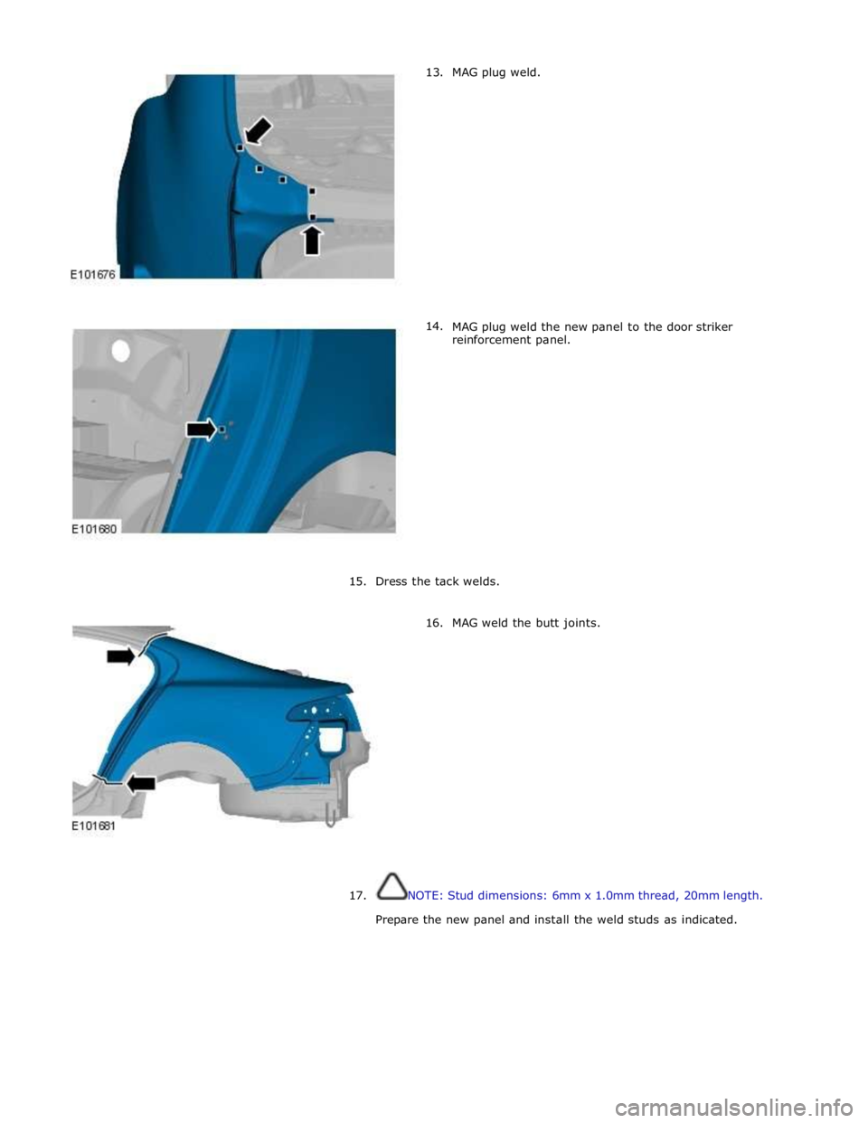
13.
14. MAG plug weld.
MAG plug weld the new panel to the door striker
reinforcement panel.
15. Dress the tack welds.
16. MAG weld the butt joints.
17.
NOTE: Stud dimensions: 6mm x 1.0mm thread, 20mm length.
Prepare the new panel and install the weld studs as indicated.
Page 3000 of 3039
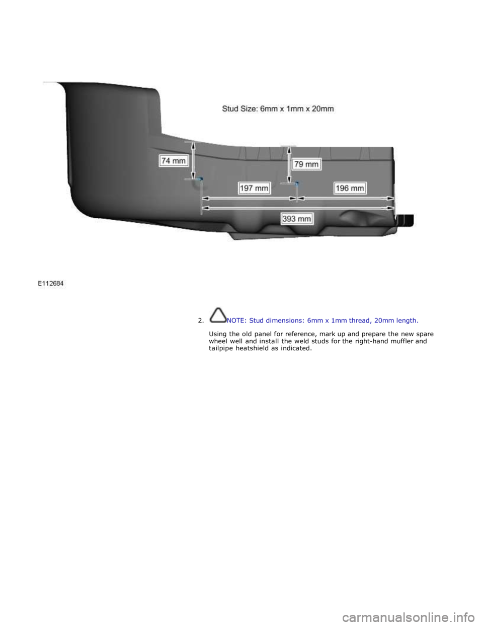
2. NOTE: Stud dimensions: 6mm x 1mm thread, 20mm length.
Using the old panel for reference, mark up and prepare the new spare
wheel well and install the weld studs for the right-hand muffler and
tailpipe heatshield as indicated.