2010 JAGUAR XFR wiring
[x] Cancel search: wiringPage 2343 of 3039
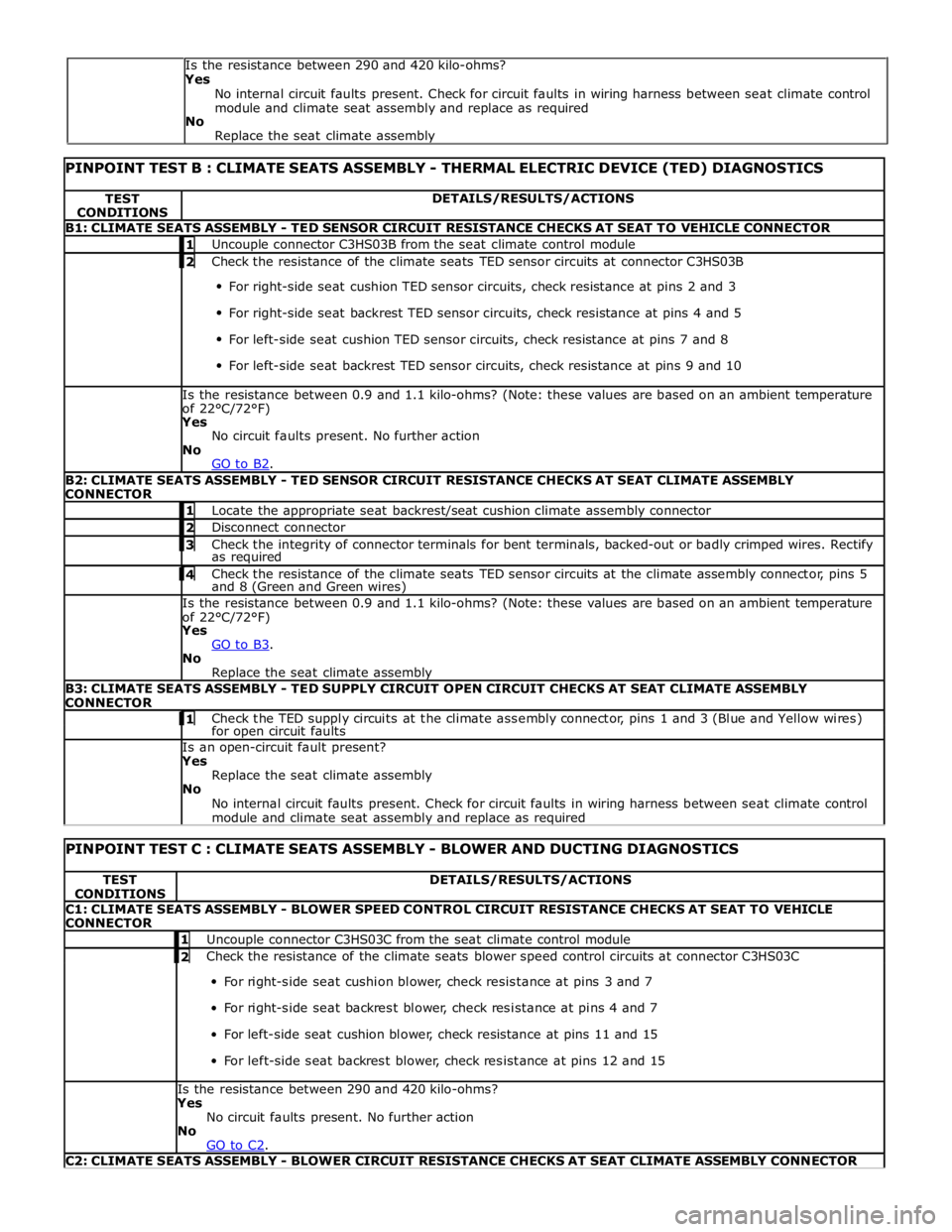
PINPOINT TEST B : CLIMATE SEATS ASSEMBLY - THERMAL ELECTRIC DEVICE (TED) DIAGNOSTICS TEST
CONDITIONS DETAILS/RESULTS/ACTIONS B1: CLIMATE SEATS ASSEMBLY - TED SENSOR CIRCUIT RESISTANCE CHECKS AT SEAT TO VEHICLE CONNECTOR 1 Uncouple connector C3HS03B from the seat climate control module 2 Check the resistance of the climate seats TED sensor circuits at connector C3HS03B For right-side seat cushion TED sensor circuits, check resistance at pins 2 and 3
For right-side seat backrest TED sensor circuits, check resistance at pins 4 and 5
For left-side seat cushion TED sensor circuits, check resistance at pins 7 and 8
For left-side seat backrest TED sensor circuits, check resistance at pins 9 and 10 Is the resistance between 0.9 and 1.1 kilo-ohms? (Note: these values are based on an ambient temperature
of 22°C/72°F) Yes
No circuit faults present. No further action
No
GO to B2. B2: CLIMATE SEATS ASSEMBLY - TED SENSOR CIRCUIT RESISTANCE CHECKS AT SEAT CLIMATE ASSEMBLY
CONNECTOR 1 Locate the appropriate seat backrest/seat cushion climate assembly connector 2 Disconnect connector 3 Check the integrity of connector terminals for bent terminals, backed-out or badly crimped wires. Rectify as required 4 Check the resistance of the climate seats TED sensor circuits at the climate assembly connector, pins 5 and 8 (Green and Green wires) Is the resistance between 0.9 and 1.1 kilo-ohms? (Note: these values are based on an ambient temperature
of 22°C/72°F) Yes
GO to B3. No
Replace the seat climate assembly B3: CLIMATE SEATS ASSEMBLY - TED SUPPLY CIRCUIT OPEN CIRCUIT CHECKS AT SEAT CLIMATE ASSEMBLY
CONNECTOR 1 Check the TED supply circuits at the climate assembly connector, pins 1 and 3 (Blue and Yellow wires) for open circuit faults Is an open-circuit fault present? Yes
Replace the seat climate assembly
No
No internal circuit faults present. Check for circuit faults in wiring harness between seat climate control
module and climate seat assembly and replace as required
PINPOINT TEST C : CLIMATE SEATS ASSEMBLY - BLOWER AND DUCTING DIAGNOSTICS TEST
CONDITIONS DETAILS/RESULTS/ACTIONS C1: CLIMATE SEATS ASSEMBLY - BLOWER SPEED CONTROL CIRCUIT RESISTANCE CHECKS AT SEAT TO VEHICLE
CONNECTOR 1 Uncouple connector C3HS03C from the seat climate control module 2 Check the resistance of the climate seats blower speed control circuits at connector C3HS03C For right-side seat cushion blower, check resistance at pins 3 and 7
For right-side seat backrest blower, check resistance at pins 4 and 7
For left-side seat cushion blower, check resistance at pins 11 and 15
For left-side seat backrest blower, check resistance at pins 12 and 15 Is the resistance between 290 and 420 kilo-ohms?
Yes
No circuit faults present. No further action
No
GO to C2. C2: CLIMATE SEATS ASSEMBLY - BLOWER CIRCUIT RESISTANCE CHECKS AT SEAT CLIMATE ASSEMBLY CONNECTOR Is the resistance between 290 and 420 kilo-ohms?
Yes
No internal circuit faults present. Check for circuit faults in wiring harness between seat climate control
module and climate seat assembly and replace as required
No
Replace the seat climate assembly
Page 2344 of 3039

1 Locate the appropriate seat backrest/seat cushion climate assembly connector 2 Disconnect connector 3 Check the integrity of connector terminals for bent terminals, backed-out or badly crimped wires. Rectify as required 4 Check the resistance of the climate seats blower circuits at the climate assembly connector, pins 2 and 4 (Violet and Black wires) Is the resistance between 290 and 420 kilo-ohms?
Yes
GO to C3. No
Replace the seat climate assembly C3: CLIMATE SEATS ASSEMBLY - BLOWER CONTROL CIRCUIT RESISTANCE CHECKS AT SEAT CLIMATE ASSEMBLY
CONNECTOR 1 Check the resistance of the climate seats blower control circuits at the climate assembly connector, pins 4 and 7 (Black and Purple wires) Is the resistance between 290 and 420 kilo-ohms?
Yes
No internal circuit faults present. Check for circuit faults in wiring harness between seat climate control
module and climate seat assembly and replace as required. If no harness faults are found, GO to C4. No
Replace the seat climate assembly C4: CLIMATE SEATS ASSEMBLY - BLOWER DUCTING INSPECTION 1 Check that the ducting is securely attached to the blower and thermal electric device 2 Check the ducting for holes, cuts or tears Is the ducting undamaged and securely attached to the blower and thermal electric device?
Yes
GO to C5. No
Replace the seat climate assembly C5: CLIMATE SEATS ASSEMBLY - EXHAUST AIRFLOW CHECKS 1 Check for blockages or restrictions at the thermal electric device exhaust vent Are blockages or restrictions present?
Yes
Rectify as required
No
GO to C6. C6: CLIMATE SEATS ASSEMBLY - BLOWER AIRFLOW CHECKS 1 Check for blockages or restrictions at the blower air intake 2 Check that the blower fan movement is not restricted Are there any air intake blockages or restrictions to the blower fan movement?
Yes
Rectify as required
No
No further action
PINPOINT TEST D : CLIMATE SEATS ASSEMBLY - THERMAL ELECTRIC DEVICE (TED) AND DUCTING
DIAGNOSTICS TEST
CONDITIONS DETAILS/RESULTS/ACTIONS D1: CLIMATE SEATS ASSEMBLY - TED SENSOR CIRCUIT RESISTANCE CHECKS AT SEAT TO VEHICLE CONNECTOR 1 Uncouple connector C3HS03B from the seat climate control module 2 Check the resistance of the climate seats TED sensor circuits at connector C3HS03B For right-side seat cushion TED sensor circuits, check resistance at pins 2 and 3
For right-side seat backrest TED sensor circuits, check resistance at pins 4 and 5
For left-side seat cushion TED sensor circuits, check resistance at pins 7 and 8
For left-side seat backrest TED sensor circuits, check resistance at pins 9 and 10 Is the resistance between 0.9 and 1.1 kilo-ohms? (Note: these values are based on an ambient temperature
of 22°C/72°F)
Yes
No circuit faults present. No further action
No
GO to D2. D2: CLIMATE SEATS ASSEMBLY - TED SENSOR CIRCUIT RESISTANCE CHECKS AT SEAT CLIMATE ASSEMBLY
CONNECTOR 1 Locate the appropriate seat backrest/seat cushion climate assembly connector 2 Disconnect connector 3 Check the integrity of connector terminals for bent terminals, backed-out or badly crimped wires. Rectify as required www.JagDocs.com
Page 2345 of 3039
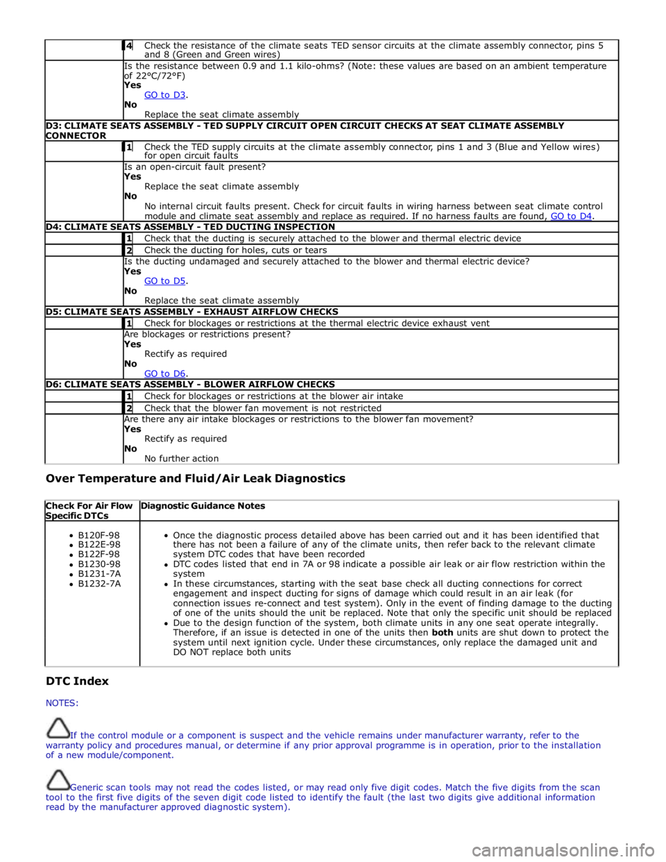
4 Check the resistance of the climate seats TED sensor circuits at the climate assembly connector, pins 5 and 8 (Green and Green wires) Is the resistance between 0.9 and 1.1 kilo-ohms? (Note: these values are based on an ambient temperature
of 22°C/72°F)
Yes
GO to D3. No
Replace the seat climate assembly D3: CLIMATE SEATS ASSEMBLY - TED SUPPLY CIRCUIT OPEN CIRCUIT CHECKS AT SEAT CLIMATE ASSEMBLY
CONNECTOR 1 Check the TED supply circuits at the climate assembly connector, pins 1 and 3 (Blue and Yellow wires) for open circuit faults Is an open-circuit fault present?
Yes
Replace the seat climate assembly
No
No internal circuit faults present. Check for circuit faults in wiring harness between seat climate control
module and climate seat assembly and replace as required. If no harness faults are found, GO to D4. D4: CLIMATE SEATS ASSEMBLY - TED DUCTING INSPECTION 1 Check that the ducting is securely attached to the blower and thermal electric device 2 Check the ducting for holes, cuts or tears Is the ducting undamaged and securely attached to the blower and thermal electric device?
Yes
GO to D5. No
Replace the seat climate assembly D5: CLIMATE SEATS ASSEMBLY - EXHAUST AIRFLOW CHECKS 1 Check for blockages or restrictions at the thermal electric device exhaust vent Are blockages or restrictions present?
Yes
Rectify as required
No
GO to D6. D6: CLIMATE SEATS ASSEMBLY - BLOWER AIRFLOW CHECKS 1 Check for blockages or restrictions at the blower air intake 2 Check that the blower fan movement is not restricted Are there any air intake blockages or restrictions to the blower fan movement?
Yes
Rectify as required
No
No further action Over Temperature and Fluid/Air Leak Diagnostics
Check For Air Flow Specific DTCs Diagnostic Guidance Notes
B120F-98
Once the diagnostic process detailed above has been carried out and it has been identified that B122E-98 there has not been a failure of any of the climate units, then refer back to the relevant climate B122F-98 system DTC codes that have been recorded B1230-98 DTC codes listed that end in 7A or 98 indicate a possible air leak or air flow restriction within the B1231-7A system B1232-7A In these circumstances, starting with the seat base check all ducting connections for correct engagement and inspect ducting for signs of damage which could result in an air leak (for connection issues re-connect and test system). Only in the event of finding damage to the ducting of one of the units should the unit be replaced. Note that only the specific unit should be replaced Due to the design function of the system, both climate units in any one seat operate integrally. Therefore, if an issue is detected in one of the units then both units are shut down to protect the system until next ignition cycle. Under these circumstances, only replace the damaged unit and DO NOT replace both units DTC Index
NOTES:
If the control module or a component is suspect and the vehicle remains under manufacturer warranty, refer to the
warranty policy and procedures manual, or determine if any prior approval programme is in operation, prior to the installation
of a new module/component.
Generic scan tools may not read the codes listed, or may read only five digit codes. Match the five digits from the scan
tool to the first five digits of the seven digit code listed to identify the fault (the last two digits give additional information
read by the manufacturer approved diagnostic system).
Page 2353 of 3039
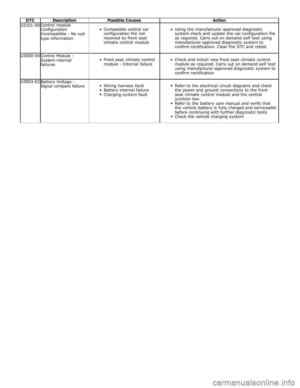
DTC Description Possible Causes Action U2101-00 Control module
Compatible central car
Using the manufacturer approved diagnostic Configuration Incompatible - No sub configuration file not system check and update the car configuration file type information received by front seat as required. Carry out on demand self test using climate control module manufacturer approved diagnostic system to confirm rectification. Clear the DTC and retest U3000-04
Control Module -
System internal
failures
Front seat climate control
module - Internal failure
Check and install new front seat climate control
module as required. Carry out on demand self test
using manufacturer approved diagnostic system to
confirm rectification U3003-62
Battery Voltage -
Signal compare failure
Wiring harness fault
Battery internal failure
Charging system fault
Refer to the electrical circuit diagrams and check
the power and ground connections to the front
seat climate control module and the central
junction box
Refer to the battery care manual and verify that
the vehicle battery is fully charged and serviceable
before continuing with further diagnostic tests
Check the vehicle charging system
Page 2360 of 3039
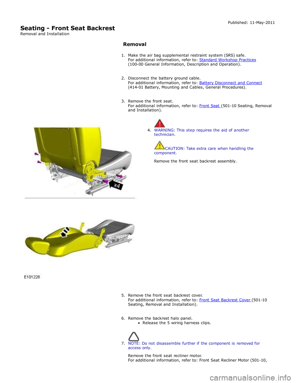
Seating - Front Seat Backrest
Removal and Installation Published: 11-May-2011
Removal
1. Make the air bag supplemental restraint system (SRS) safe.
For additional information, refer to: Standard Workshop Practices (100-00 General Information, Description and Operation).
2. Disconnect the battery ground cable.
For additional information, refer to: Battery Disconnect and Connect (414-01 Battery, Mounting and Cables, General Procedures).
3. Remove the front seat.
For additional information, refer to: Front Seat (501-10 Seating, Removal and Installation).
4. WARNING: This step requires the aid of another
technician.
CAUTION: Take extra care when handling the
component.
Remove the front seat backrest assembly.
5. Remove the front seat backrest cover.
For additional information, refer to: Front Seat Backrest Cover (501-10 Seating, Removal and Installation).
6. Remove the backrest halo panel.
Release the 5 wiring harness clips.
7. NOTE: Do not disassemble further if the component is removed for
access only.
Remove the front seat recliner motor.
For additional information, refer to: Front Seat Recliner Motor (501-10,
Page 2483 of 3039
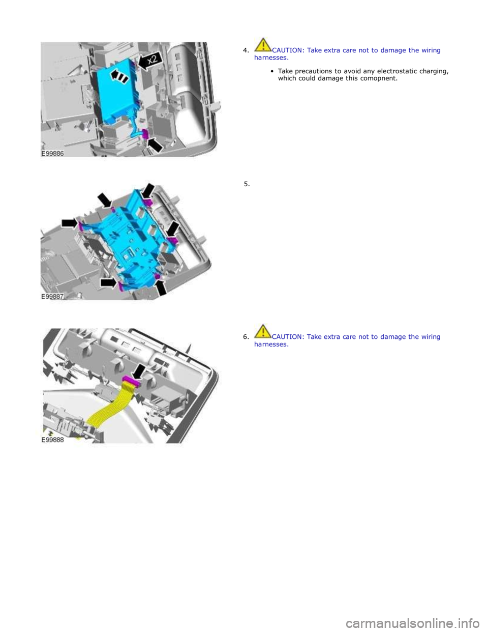
4. CAUTION: Take extra care not to damage the wiring
harnesses.
Take precautions to avoid any electrostatic charging,
which could damage this comopnent.
5.
6. CAUTION: Take extra care not to damage the wiring
harnesses.
Page 2485 of 3039
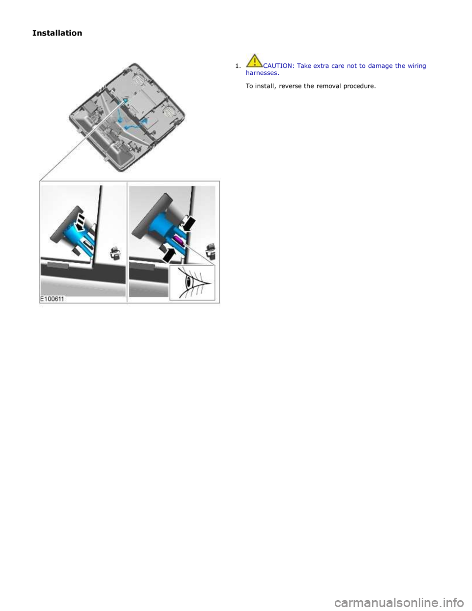
Installation
1. CAUTION: Take extra care not to damage the wiring
harnesses.
To install, reverse the removal procedure.
Page 2495 of 3039
Published: 18-Mar-2014
Handles, Locks, Latches and Entry Systems - Locks, Latches and Entry Systems
Diagnosis and Testing
Principle of Operation
For a detailed description of the locks, latches and entry systems and operation, refer to the relevant Description and
Operation section of the workshop manual. REFER to: Handles, Locks, Latches and Entry Systems (501-14, Description and
Operation).
Inspection and Verification
CAUTION: Diagnosis by substitution from a donor vehicle is NOT acceptable. Substitution of control modules does not
guarantee confirmation of a fault and may also cause additional faults in the vehicle being checked and/or the donor vehicle
NOTE: Check and rectify basic faults before beginning diagnostic routines involving pinpoint tests
1. Verify the customer concern, to be sure the correct issue is investigated
2. Visually inspect for obvious signs of damage and system integrity
Visual Inspection
Mechanical Electrical
Incorrectly aligned door(s), hood or tailgate
Fuel filler door lock actuator
Hood release handle
Hood release cables
Hood latch(es)
Exterior door handle(s)
Interior door handle(s)
Cable(s)
Tailgate release switch
Rear window release switch
Fuses
Wiring harness
Wiring connector(s)
Door lock actuator(s)
Remote transmitter (key-fob or smart key)
Central locking switches
Controller Area Network (CAN) circuits
Radio frequency (RF) receiver
Central junction box (CJB)
Loose or corroded connections
3. If an obvious cause for an observed or reported concern is found, correct the cause (if possible) before proceeding to
the next step
4. If the cause is not visually evident verify the symptom and refer to the Symptom Chart, alternatively check for
Diagnostic Trouble Codes (DTCs) and refer to the DTC Index
Symptom Chart
NOTE: Complete the diagnostic steps below to confirm any concern prior to replacing any component
Symptom Possible Causes Action The message center indicates that the
hood, the luggage compartment is
open when it appears to be closed
Incorrect striker
alignment/adjustment
Ajar switch circuit short circuit to
ground
Ajar switch failure
Check/adjust the strikers as
necessary
Check for DTCs indicating an ajar
switch fault. Refer to the DTC index Vehicle indicates a miss-lock when the
hood, luggage compartment appear to
be closed Fuel flap does not lock/unlock
Fuel flap cable detached from body
Fuel flap actuator detached from
mounting bracket
Fuel flap actuator disconnected
Fuel flap actuator failure
Check the condition and installation
of the fuel flap cable
Check the security of the fuel flap
actuator and bracket
Check the security of the actuator
electrical connector
Check for DTCs indicating a fuel flap
actuator fault. Refer to the DTC
index Door(s) will not unlatch/open when
using outside door handle
Exterior door handle
condition/installation
Exterior release cable disconnected
from exterior door handle or door
latch
Check the exterior door handle
condition and installation
Check the condition and security of
the exterior release cable
Single door will not open from the