2010 JAGUAR XFR wiring
[x] Cancel search: wiringPage 2781 of 3039
Front End Sheet Metal Repairs - Front Fender Support Bracket
Removal and Installation
Removal Published: 11-May-2011
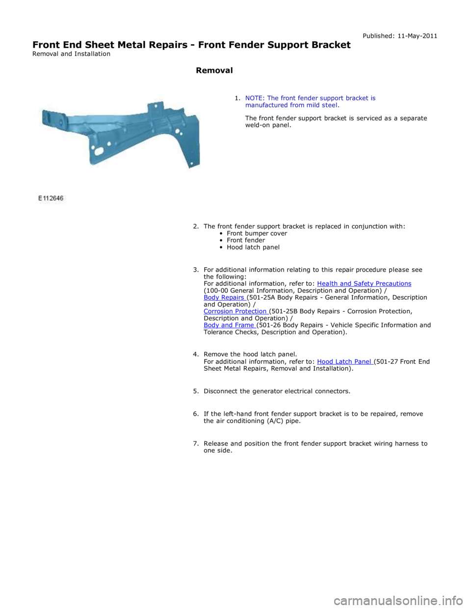
1. NOTE: The front fender support bracket is
manufactured from mild steel.
The front fender support bracket is serviced as a separate
weld-on panel.
2. The front fender support bracket is replaced in conjunction with:
Front bumper cover
Front fender
Hood latch panel
3. For additional information relating to this repair procedure please see
the following:
For additional information, refer to: Health and Safety Precautions (100-00 General Information, Description and Operation) /
Body Repairs (501-25A Body Repairs - General Information, Description and Operation) /
Corrosion Protection (501-25B Body Repairs - Corrosion Protection, Description and Operation) /
Body and Frame (501-26 Body Repairs - Vehicle Specific Information and Tolerance Checks, Description and Operation).
4. Remove the hood latch panel.
For additional information, refer to: Hood Latch Panel (501-27 Front End Sheet Metal Repairs, Removal and Installation).
5. Disconnect the generator electrical connectors.
6. If the left-hand front fender support bracket is to be repaired, remove
the air conditioning (A/C) pipe.
7. Release and position the front fender support bracket wiring harness to
one side.
Page 2785 of 3039
Transmission (307-01A Automatic Transmission/Transaxle - V6 3.0L Petrol, Removal) /
Transmission - 4.2L (307-01, Removal) /
Transmission - V8 5.0L Petrol/V8 S/C 5.0L Petrol (307-01B Automatic Transmission/Transaxle - TDV6 3.0L Diesel /V8 5.0L Petrol/V8 S/C 5.0L
Petrol, Removal) /
Front Shock Absorber (204-01 Front Suspension, Removal and Installation) /
Front Subframe - 2.7L Diesel (502-00, Removal and Installation) /
Front Subframe - V6 3.0L Petrol (502-00 Uni-Body, Subframe and Mounting System, Removal and Installation) /
Front Subframe - 4.2L, Vehicles Without: Supercharger (502-00, Removal
and Installation) /
Front Subframe - 4.2L, Vehicles With: Supercharger (502-00, Removal
and Installation).
8. Remove the pedestrian protection hood actuator.
For additional information, refer to: Pedestrian Protection Hood Actuator LH (501-20C Pedestrian Protection System, Removal and Installation) / Pedestrian Protection Hood Actuator RH (501-20C Pedestrian Protection System, Removal and Installation).
9. If the drivers side front side member and suspension top mount is to be
repaired, remove the brake master cylinder and reservoir.
For additional information, refer to: Brake Master Cylinder (206-06 Hydraulic Brake Actuation, Removal and Installation) /
Brake Fluid Reservoir (206-06 Hydraulic Brake Actuation, Removal and Installation).
10. If the left-hand front side member and suspension top mount assembly
is to be repaired, remove the fuel supply and return lines.
11. Release and position the front side member wiring harness to one side.
12. Remove any remaining miscellaneous components from the repair area.
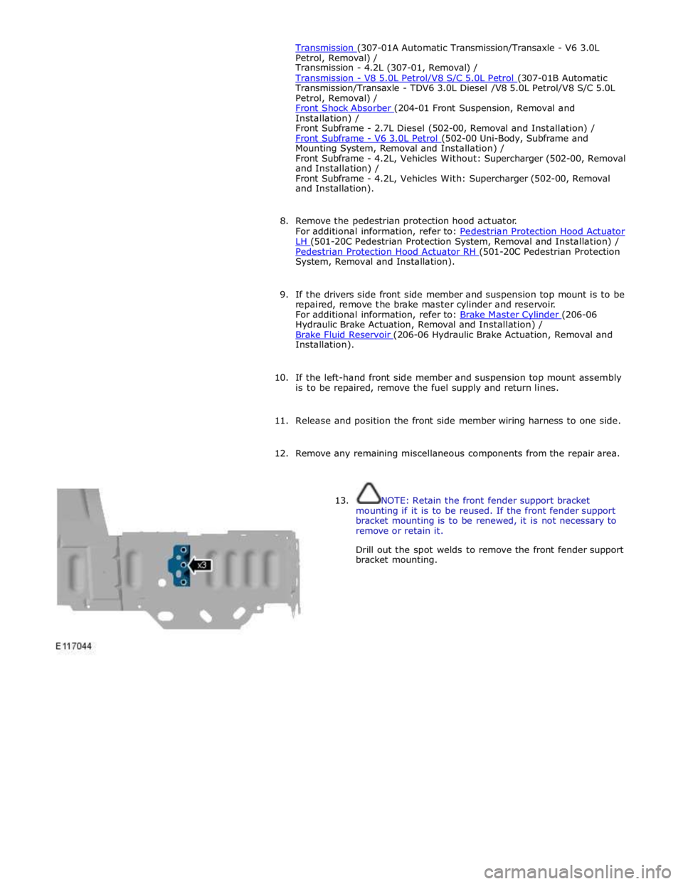
13. NOTE: Retain the front fender support bracket
mounting if it is to be reused. If the front fender support
bracket mounting is to be renewed, it is not necessary to
remove or retain it.
Drill out the spot welds to remove the front fender support
bracket mounting.
Page 2798 of 3039
Actuation, Removal and Installation).
12. Remove the left-hand and right-hand front seats.
For additional information, refer to: Front Seat (501-10 Seating, Removal and Installation).
13. Remove the heater core and evaporator core housing.
For additional information, refer to: Heater Core and Evaporator Core Housing (412-01 Climate Control, Removal and Installation).
14. Remove the front safety belt retractor.
For additional information, refer to: Front Safety Belt Retractor (501-20A Safety Belt System, Removal and Installation).
15. Remove the B-pillar side impact sensor.
For additional information, refer to: B-Pillar Side Impact Sensor (501-20B Supplemental Restraint System, Removal and Installation).
16. Remove the left-hand and right-hand front floor covering.
17. Remove the rear floor covering.
18. If the left-hand front side member and suspension top mount assembly
is to be repaired, remove the left-hand rear foot well duct.
19. If the right-hand front side member and suspension top mount assembly
is to be repaired, remove the right-hand rear foot well duct.
20. If the drivers side front side member and suspension top mount is being
repaired, remove the pedal box.
21. Release and position the insulating material at the inner bulkhead to
one side.
22. Release and position the inner bulkhead and floor panel wiring harness
to one side.
23. Drain the fuel tank.
For additional information, refer to: Fuel Tank Draining (310-00 Fuel System - General Information, General Procedures).
24. If the left-hand front side member and suspension top mount assembly
is to be repaired, remove the left-hand under shield.
25. If the right-hand front side member and suspension top mount assembly
is to be repaired, remove the right-hand under shield.
26. If the left-hand front side member and suspension top mount assembly
is to be repaired, remove the fuel supply and return pipes.
27. For diesel engine vehicles only, if the left-hand front side member and
suspension top mount assembly is to be repaired, remove the fuel
cooler.
28. If the right-hand front side member and suspension top mount assembly
is to be repaired, release and position the underfloor wiring harness to
Page 2799 of 3039
one side.
29. If the right-hand front side member and suspension top mount assembly
is to be repaired, remove the front to rear brake pipes.
30. Remove the exhaust heat shields.
31. Release and position the front side member and suspension top mount
wiring harness to one side.
32. Remove any remaining miscellaneous components from the repair area
as necessary.
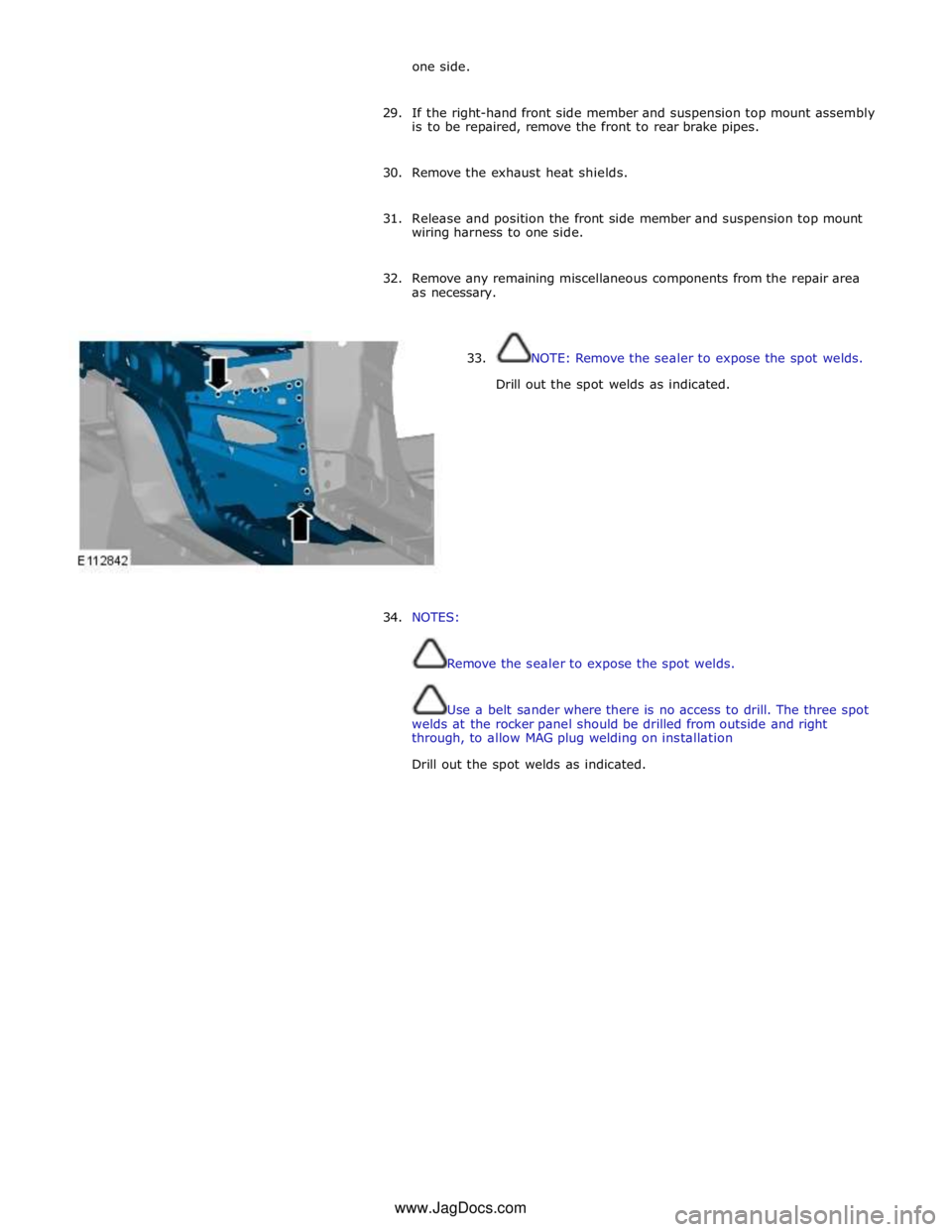
33. NOTE: Remove the sealer to expose the spot welds.
Drill out the spot welds as indicated.
34. NOTES:
Remove the sealer to expose the spot welds.
Use a belt sander where there is no access to drill. The three spot
welds at the rocker panel should be drilled from outside and right
through, to allow MAG plug welding on installation
Drill out the spot welds as indicated. www.JagDocs.com
Page 2821 of 3039
Lighting, Removal and Installation).
7. Remove the condenser core.
For additional information, refer to: Condenser Core - 2.7L Diesel
(412-03, Removal and Installation) /
Condenser Core - V6 3.0L Petrol (412-03 Air Conditioning, Removal and Installation) /
Condenser Core - 4.2L, Vehicles Without: Supercharger (412-03, Removal
and Installation) /
Condenser Core - 4.2L, Vehicles With: Supercharger (412-03, Removal
and Installation).
8. Remove the radiator.
For additional information, refer to: Radiator (303-03A, Removal and
Installation) /
Radiator (303-03B Engine Cooling - V6 3.0L Petrol, Removal and Installation) /
Radiator - Vehicles With: Supercharger (303-03C, Removal and
Installation) /
Radiator - Vehicles Without: Supercharger (303-03C, Removal and
Installation).
9. Remove the both hood latch panel braces.
10. Remove the cooling fan upper shroud.
11. Remove both crash sensors.
For additional information, refer to: Crash Sensor (501-20B Supplemental Restraint System, Removal and Installation).
12. Remove the both hood latches.
13. Remove the hood safety hook guide.
14. Remove both hood latch panel buffers.
15. Release and lay aside the hood latch panel wiring harness.
16. Remove the old panel.
Page 2829 of 3039
(414-01 Battery, Mounting and Cables, General Procedures).
6. Disconnect the generator electrical connectors.
7. Remove the windshield glass.
For additional information, refer to: Windshield Glass (501-11 Glass, Frames and Mechanisms, Removal and Installation).
8. Remove the rear window glass.
For additional information, refer to: Rear Window Glass (501-11 Glass, Frames and Mechanisms, Removal and Installation).
9. Remove the roof opening panel frame.
For additional information, refer to: Roof Opening Panel Frame (501-17 Roof Opening Panel, Removal and Installation).
10. Remove the driver and passenger side front scuff plate trim panels.
For additional information, refer to: Front Scuff Plate Trim Panel (501-05 Interior Trim and Ornamentation, Removal and Installation).
11. Remove the driver and passenger side rear scuff plate trim panels.
For additional information, refer to: Rear Scuff Plate Trim Panel (501-05 Interior Trim and Ornamentation, Removal and Installation).
12. Remove the driver and passenger side air curtain modules.
For additional information, refer to: Side Air Curtain Module (501-20B Supplemental Restraint System, Removal and Installation).
13. Remove the rear seat backrest.
14. Remove the driver and passenger side rear safety belt retractors.
For additional information, refer to: Rear Safety Belt Retractor (501-20A Safety Belt System, Removal and Installation).
15. Remove the rear center safety belt retractor.
For additional information, refer to: Rear Center Safety Belt Retractor (501-20A Safety Belt System, Removal and Installation).
16. Remove the driver and passenger side RF filters.
17. Remove the diversity antenna module.
18. Remove the antenna.
For additional information, refer to: Navigation System Antenna (419-07 Navigation System, Removal and Installation).
19. Release and position the roof wiring harnesses to one side
20. Position the roof opening panel front and rear drain hoses to one side.
21. Remove the driver and passenger side roof mouldings.
22. Drill out the spot welds.
www.JagDocs.com
Page 2836 of 3039
(414-01 Battery, Mounting and Cables, General Procedures).
6. Disconnect the generator electrical connectors.
7. Remove the windshield glass.
For additional information, refer to: Windshield Glass (501-11 Glass, Frames and Mechanisms, Removal and Installation).
8. Remove the rear window glass.
For additional information, refer to: Rear Window Glass (501-11 Glass, Frames and Mechanisms, Removal and Installation).
9. Remove the headliner.
For additional information, refer to: Headliner (501-05 Interior Trim and Ornamentation, Removal and Installation).
10. Remove the driver and passenger side front scuff plate trim panels.
For additional information, refer to: Front Scuff Plate Trim Panel (501-05 Interior Trim and Ornamentation, Removal and Installation).
11. Remove the driver and passenger side rear scuff plate trim panels.
For additional information, refer to: Rear Scuff Plate Trim Panel (501-05 Interior Trim and Ornamentation, Removal and Installation).
12. Remove the driver and passenger side air curtain modules.
For additional information, refer to: Side Air Curtain Module (501-20B Supplemental Restraint System, Removal and Installation).
13. Remove the rear seat backrest.
14. Remove the driver and passenger side rear safety belt retractors.
For additional information, refer to: Rear Safety Belt Retractor (501-20A Safety Belt System, Removal and Installation).
15. Remove the rear center safety belt retractor.
For additional information, refer to: Rear Center Safety Belt Retractor (501-20A Safety Belt System, Removal and Installation).
16. Remove the driver and passenger side RF filters.
17. Remove the diversity antenna module.
18. Remove the antenna.
For additional information, refer to: Navigation System Antenna (419-07 Navigation System, Removal and Installation).
19. Release and position the roof wiring harnesses to one side
20. Remove the driver and passenger side roof mouldings.
21. Drill out the spot welds.
Page 2846 of 3039
Ornamentation, Removal and Installation).
8. Remove the windshield glass.
For additional information, refer to: Windshield Glass (501-11 Glass, Frames and Mechanisms, Removal and Installation).
9. Remove the pedestrian protection hood actuator.
For additional information, refer to: Pedestrian Protection Hood Actuator LH (501-20C Pedestrian Protection System, Removal and Installation) / Pedestrian Protection Hood Actuator RH (501-20C Pedestrian Protection System, Removal and Installation).
10. Release and position the floor covering to one side.
11. Release and position the bulkhead insulating material to one side.
12. Release and position the inner rocker panel wiring harness to one side.
13. Remove the wheel and tire.
For additional information, refer to: Wheel and Tire (204-04 Wheels and Tires, Removal and Installation).
14. Remove the underfloor splash shield.
15. If the right-hand A-pillar outer panel is to be repaired, release and
position the underfloor wiring harness to one side.
16. Remove the front fender.
For additional information, refer to: Front Fender (501-27 Front End Sheet Metal Repairs, Removal and Installation).
17. Remove the front door.
For additional information, refer to: Front Door (501-03 Body Closures, Removal and Installation).
18. Remove the upper and lower front door hinges.
19. Remove the hood.
For additional information, refer to: Hood (501-02 Front End Body Panels, Removal and Installation).
20. Remove the hood hinge.