2010 JAGUAR XFR remove seats
[x] Cancel search: remove seatsPage 73 of 3039
Supplementary Restraint System (SRS) Precautions
WARNING: Do not install rear facing child seats in the front passenger seat.
The SRS contains components which are potentially hazardous to service personnel if not handled correctly. The following
guidelines and precautions are intended to alert personnel to potential sources of danger and emphasise the importance of
ensuring the integrity of the SRS components installed to the vehicle.
WARNING: The following precautions MUST be adhered to when working on the SRS system:
The correct procedures must always be used when working on SRS components.
Persons working on the SRS system must be fully trained and have been issued with the safety guidelines.
The airbag modules contain extremely flammable and hazardous compounds. Contact with water, acids or heavy
metals may produce harmful or explosive results. Do not dismantle, incinerate or bring into contact with electricity
before the unit has been deployed.
Always replace a seat belt assembly that has withstood the strain of a severe vehicle impact or if the webbing
shows signs of fraying.
Always disconnect the vehicle battery before carrying out any electric welding on a vehicle installed with an SRS
system.
CAUTION: Do not expose airbag modules or seat belt pre-tensioners to temperatures exceeding 85° C (185° F).
It should be noted that these precautions are not restricted to operations performed when servicing the SRS system. The same
care should be exercised when working on ancillary systems and components located in the vicinity of SRS components; these
include but are not limited to:
Steering wheel airbag, rotary coupler.
Passenger front airbag.
Head airbag modules - front and rear.
Seat belt pre-tensioners.
SRS harnesses, link leads and connectors.
Side (thorax) air bags.
Making the system safe
Before working on or in the vicinity of SRS components, make sure the system is rendered safe by performing the following
operations:
Remove the ignition key.
Disconnect battery, earth lead first.
Wait 2 minutes for the SRS power circuit to discharge before commencing work.
NOTE: The SRS uses energy reserve capacitors to keep the system active in the event of electrical supply failure under
crash conditions. It is necessary to allow the capacitors sufficient time to discharge (2 minutes) in order to avoid the risk of
accidental deployment.
Installation
In order to make sure system integrity, it is essential that the SRS system is regularly checked and maintained so that it is
ready for effective operation in the event of a collision. Carefully inspect SRS components before installation. Do not install a
part that shows signs of being dropped or improperly handled, such as dents, cracks or deformation.
WARNING: The integrity of the SRS systems is critical for safety reasons. Make sure the following precautions are always
adhered to:
Do not install accessories or other objects to trim panels which cover ITS airbags.
Never install used SRS components from another vehicle or attempt to repair an SRS component.
When repairing an SRS system, only use genuine new parts.
Never apply electrical power to an SRS component unless instructed to do so as part of an approved test
procedure.
Special fixings are necessary for installing an airbag module – do not use other fixings and make sure that all
fixings are tightened to the correct torque.
Always use new fixings when replacing an SRS component.
CAUTIONS:
Take care not to trap airbag modules when installing interior trim components.
Make sure SRS components are not contaminated by oil or grease.
NOTES:
Following seat belt pre-tensioner deployment, the seat belts can still be used as conventional seat belts but will need to
Page 301 of 3039

it may turn out to be the most important.
2. Do not touch anything until a road test and a thorough visual inspection of the vehicle have been carried out. Leave the
tire pressures and vehicle load just where they were when the condition was first observed. Adjusting tire pressures,
vehicle load or making other adjustments may reduce the conditions intensity to a point where it cannot be identified
clearly. It may also inject something new into the system, preventing correct diagnosis.
3. Make a visual inspection as part of the preliminary diagnosis routine, writing down anything that does not look right.
Note tire pressures, but do not adjust them yet. Note leaking fluids, loose nuts and bolts, or bright spots where
components may be rubbing against each other. Check the luggage compartment for unusual loads.
4. Road test the vehicle and define the condition by reproducing it several times during the road test.
5. Carry out the Road Test Quick Checks as soon as the condition is reproduced. This will identify the correct diagnostic
procedure. Carry out the Road Test Quick Checks more than once to verify they are providing a valid result. Remember,
the Road Test Quick Checks may not tell where the concern is, but they will tell where it is not.
Road Test Quick Checks
1. 24-80 km/h (15-50 miles/h): With light acceleration, a moaning noise is heard and possibly a vibration is felt in the
front floor pan. It is usually worse at a particular engine speed and at a particular throttle setting during acceleration at
that speed. It may also produce a moaning sound, depending on what component is causing it. Refer to Tip-In Moan in
the Symptom Chart.
2. Acceleration/deceleration: With slow acceleration and deceleration, a shake is sometimes noticed in the steering
wheel/column, seats, front floor pan, front door trim panel or front end sheet metal. It is a low frequency vibration
(around 9-15 cycles per second). It may or may not be increased by applying brakes lightly. Refer to Idle Boom/Shake
/Vibration in the Symptom Chart.
3. High speed: A vibration is felt in the front floor pan or seats with no visible shake, but with an accompanying sound or
rumble, buzz, hum, drone or booming noise. Coast with the clutch pedal depressed or shift control selector lever in
neutral and engine idling. If vibration is still evident, it may be related to wheels, tires, front brake discs, wheel hubs
or front wheel bearings. Refer to High Speed Shake in the Symptom Chart.
4. Engine rpm sensitive: A vibration is felt whenever the engine reaches a particular rpm. It will disappear in neutral
coasts. The vibration can be duplicated by operating the engine at the problem rpm while the vehicle is stationary. It
can be caused by any component, from the accessory drive belt to the torque converter which turns at engine speed
when the vehicle is stopped. Refer to High Speed Shake in the Symptom Chart.
5. Noise/vibration while turning: Clicking, popping, or grinding noises may be due to a worn, damaged, or incorrectly
installed front wheel bearing, rear drive half shaft or CV joint.
6. Noise/vibration that is road speed relative: This noise/vibration can be diagnosed independent of engine speed or gear
selected (engine speed varies but torque and road speed remain constant). The cause may be a rear drive
axle/differential whine.
Road Conditions
An experienced technician will always establish a route that will be used for all NVH diagnosis road tests. The road selected
should be reasonably smooth, level and free of undulations (unless a particular condition needs to be identified). A smooth
asphalt road that allows driving over a range of speeds is best. Gravel or bumpy roads are unsuitable because of the additional
road noise produced. Once the route is established and consistently used, the road noise variable is eliminated from the test
results.
NOTE: Some concerns may be apparent only on smooth asphalt roads.
If a customer complains of a noise or vibration on a particular road and only on a particular road, the source of the concern
may be the road surface. If possible, try to test the vehicle on the same type of road.
Vehicle Preparation
Carry out a thorough visual inspection of the vehicle before carrying out the road test. Note anything which is unusual. Do not
repair or adjust any condition until the road test is carried out, unless the vehicle is inoperative or the condition could pose a
hazard to the technician.
After verifying the condition has been corrected, make sure all components removed have been installed.
Lift Test
After a road test, it is sometimes useful to do a similar test on a lift.
When carrying out the high-speed shake diagnosis or engine accessory vibration diagnosis on a lift, observe the following
precautions:
WARNING: If only one drive wheel is allowed to rotate, speed must be limited to 55 km/h (35 miles/h) indicated on the
speedometer since actual wheel speed will be twice that indicated on the speedometer. Speed exceeding 55 km/h (35 miles/h)
or allowing the drive wheel to hang unsupported could result in tire disintegration, differential failure, constant velocity joint
Page 2253 of 3039
Interior Trim and Ornamentation - Headliner
Removal and Installation
Removal
NOTE: Removal steps in this procedure may contain installation details. Published: 11-May-2011
1. Refer to: Battery Disconnect and Connect (414-01 Battery, Mounting and Cables, General Procedures).
2. Refer to: Interior Rear View Mirror (501-09 Rear View Mirrors, Removal and Installation).
3. Refer to: Overhead Console (501-12 Instrument Panel and Console, Removal and Installation).
4.
Remove both sun visors.
Refer to: Sun Visor (501-05 Interior Trim and Ornamentation, Removal and Installation).
5.
Remove both A-pillar trim panels.
Refer to: A-Pillar Trim Panel (501-05 Interior Trim and Ornamentation, Removal and Installation).
6.
Remove both B-pillar upper trim panels.
Refer to: B-Pillar Upper Trim Panel (501-05 Interior Trim and Ornamentation, Removal and Installation).
7.
Remove both C-pillar trim panels.
Refer to: C-Pillar Trim Panel (501-05 Interior Trim and Ornamentation, Removal and Installation).
8.
Remove both front seats.
Refer to: Front Seat (501-10 Seating, Removal and Installation).
9. Refer to: Rear Seat Cushion (501-10 Seating, Removal and Installation).
Page 2380 of 3039
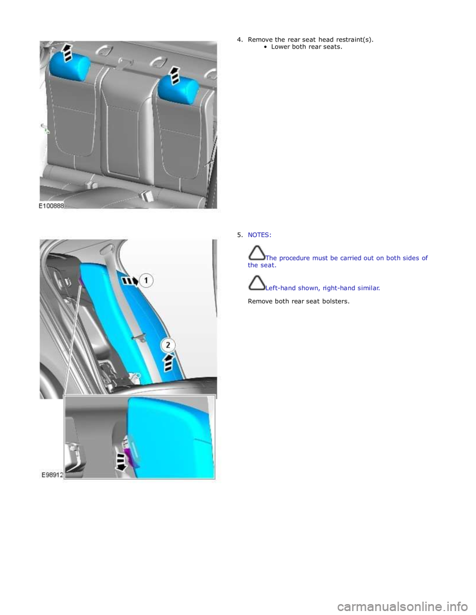
4. Remove the rear seat head restraint(s).
Lower both rear seats.
5. NOTES:
The procedure must be carried out on both sides of
the seat.
Left-hand shown, right-hand similar.
Remove both rear seat bolsters.
Page 2462 of 3039
Instrument Panel and Console - Floor Console Side Trim Panel
Removal and Installation
Removal
NOTES: Published: 11-May-2011
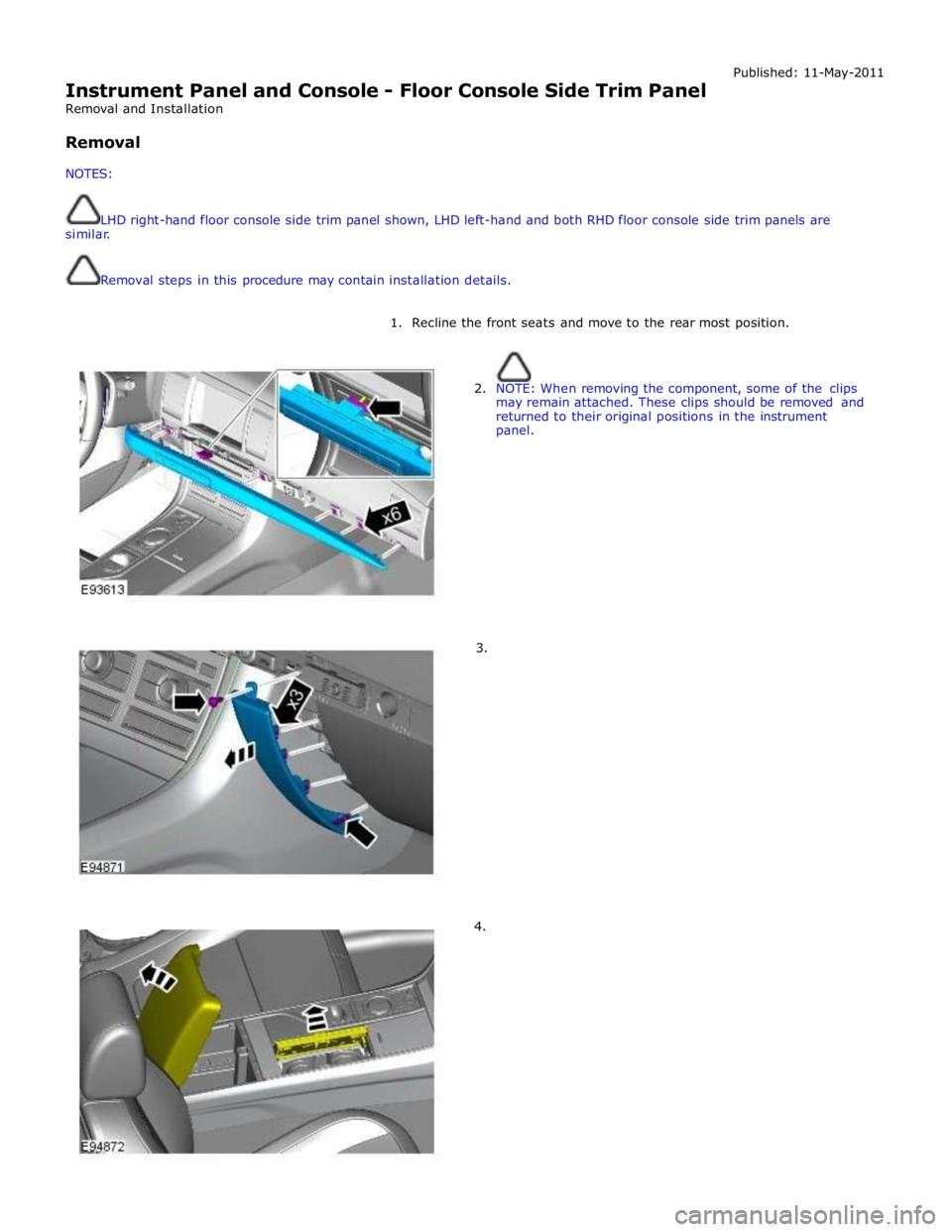
LHD right-hand floor console side trim panel shown, LHD left-hand and both RHD floor console side trim panels are
similar.
Removal steps in this procedure may contain installation details.
1. Recline the front seats and move to the rear most position.
2. NOTE: When removing the component, some of the clips
may remain attached. These clips should be removed and
returned to their original positions in the instrument
panel.
3.
4.
Page 2798 of 3039
Actuation, Removal and Installation).
12. Remove the left-hand and right-hand front seats.
For additional information, refer to: Front Seat (501-10 Seating, Removal and Installation).
13. Remove the heater core and evaporator core housing.
For additional information, refer to: Heater Core and Evaporator Core Housing (412-01 Climate Control, Removal and Installation).
14. Remove the front safety belt retractor.
For additional information, refer to: Front Safety Belt Retractor (501-20A Safety Belt System, Removal and Installation).
15. Remove the B-pillar side impact sensor.
For additional information, refer to: B-Pillar Side Impact Sensor (501-20B Supplemental Restraint System, Removal and Installation).
16. Remove the left-hand and right-hand front floor covering.
17. Remove the rear floor covering.
18. If the left-hand front side member and suspension top mount assembly
is to be repaired, remove the left-hand rear foot well duct.
19. If the right-hand front side member and suspension top mount assembly
is to be repaired, remove the right-hand rear foot well duct.
20. If the drivers side front side member and suspension top mount is being
repaired, remove the pedal box.
21. Release and position the insulating material at the inner bulkhead to
one side.
22. Release and position the inner bulkhead and floor panel wiring harness
to one side.
23. Drain the fuel tank.
For additional information, refer to: Fuel Tank Draining (310-00 Fuel System - General Information, General Procedures).
24. If the left-hand front side member and suspension top mount assembly
is to be repaired, remove the left-hand under shield.
25. If the right-hand front side member and suspension top mount assembly
is to be repaired, remove the right-hand under shield.
26. If the left-hand front side member and suspension top mount assembly
is to be repaired, remove the fuel supply and return pipes.
27. For diesel engine vehicles only, if the left-hand front side member and
suspension top mount assembly is to be repaired, remove the fuel
cooler.
28. If the right-hand front side member and suspension top mount assembly
is to be repaired, release and position the underfloor wiring harness to
Page 2828 of 3039
Published: 11-May-2011
Roof Sheet Metal Repairs - Roof Panel Vehicles With: Sliding Roof Opening
Panel
Removal and Installation
Removal
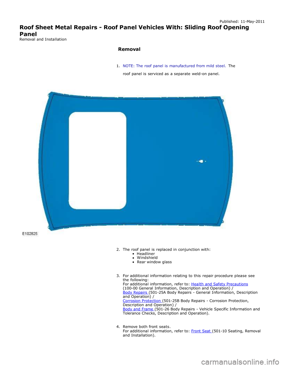
1. NOTE: The roof panel is manufactured from mild steel. The
roof panel is serviced as a separate weld-on panel.
2. The roof panel is replaced in conjunction with:
Headliner
Windshield
Rear window glass
3. For additional information relating to this repair procedure please see
the following:
For additional information, refer to: Health and Safety Precautions (100-00 General Information, Description and Operation) /
Body Repairs (501-25A Body Repairs - General Information, Description and Operation) /
Corrosion Protection (501-25B Body Repairs - Corrosion Protection, Description and Operation) /
Body and Frame (501-26 Body Repairs - Vehicle Specific Information and Tolerance Checks, Description and Operation).
4. Remove both front seats.
For additional information, refer to: Front Seat (501-10 Seating, Removal and Installation).
Page 2835 of 3039
Published: 11-May-2011
Roof Sheet Metal Repairs - Roof Panel Vehicles Without: Sliding Roof Opening
Panel
Removal and Installation
Removal
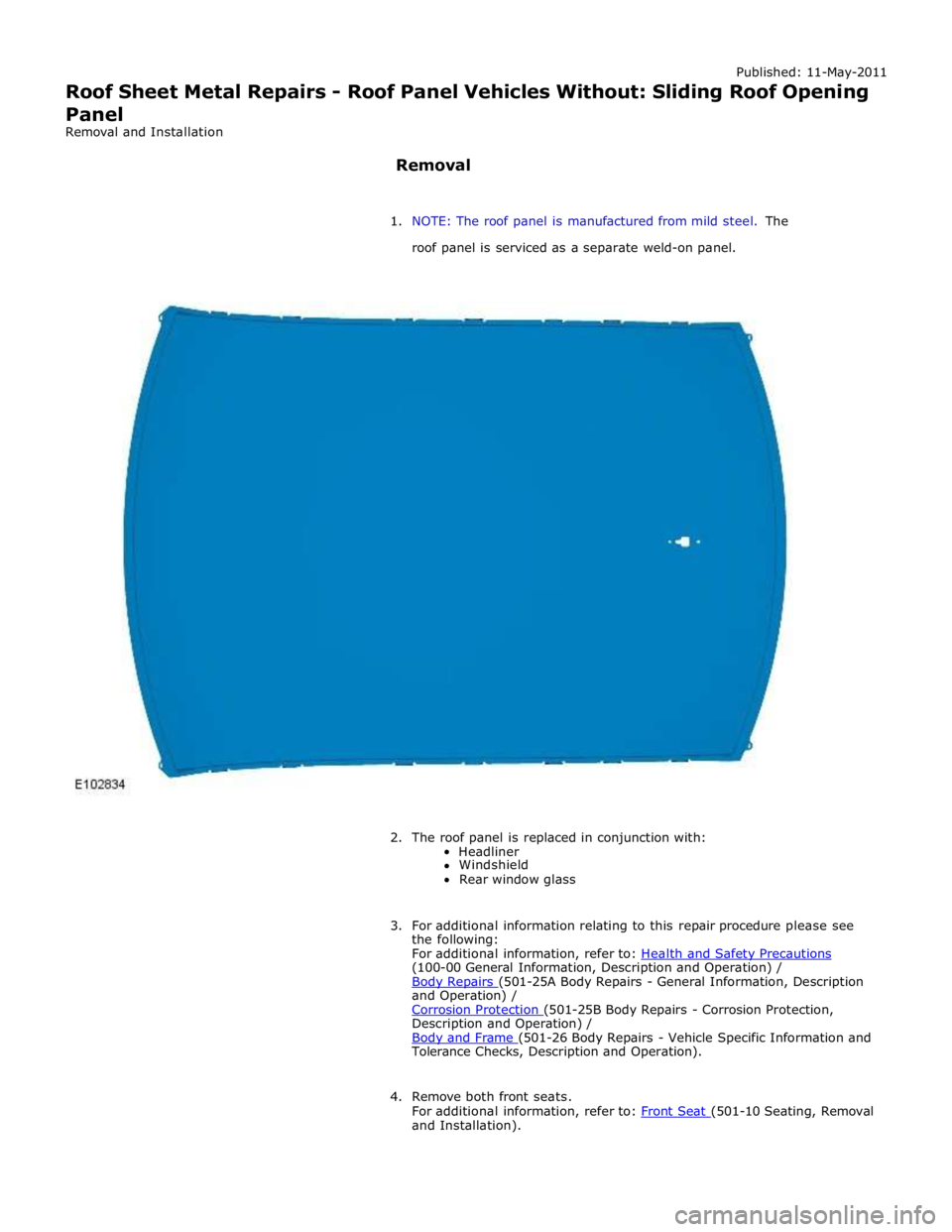
1. NOTE: The roof panel is manufactured from mild steel. The
roof panel is serviced as a separate weld-on panel.
2. The roof panel is replaced in conjunction with:
Headliner
Windshield
Rear window glass
3. For additional information relating to this repair procedure please see
the following:
For additional information, refer to: Health and Safety Precautions (100-00 General Information, Description and Operation) /
Body Repairs (501-25A Body Repairs - General Information, Description and Operation) /
Corrosion Protection (501-25B Body Repairs - Corrosion Protection, Description and Operation) /
Body and Frame (501-26 Body Repairs - Vehicle Specific Information and Tolerance Checks, Description and Operation).
4. Remove both front seats.
For additional information, refer to: Front Seat (501-10 Seating, Removal and Installation).