2010 JAGUAR XFR service
[x] Cancel search: servicePage 2510 of 3039
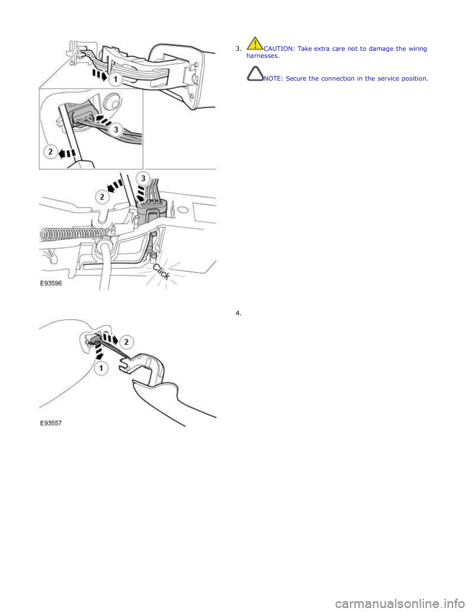
3. CAUTION: Take extra care not to damage the wiring
harnesses.
NOTE: Secure the connection in the service position.
4.
Page 2515 of 3039
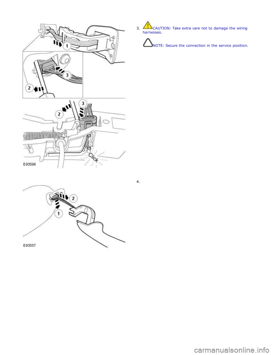
3. CAUTION: Take extra care not to damage the wiring
harnesses.
NOTE: Secure the connection in the service position.
4.
Page 2539 of 3039
5 Receiver diodes (100% light received) 6 Water droplets/film 7 Receiver diodes (less than 100% light received) 8 Lost light
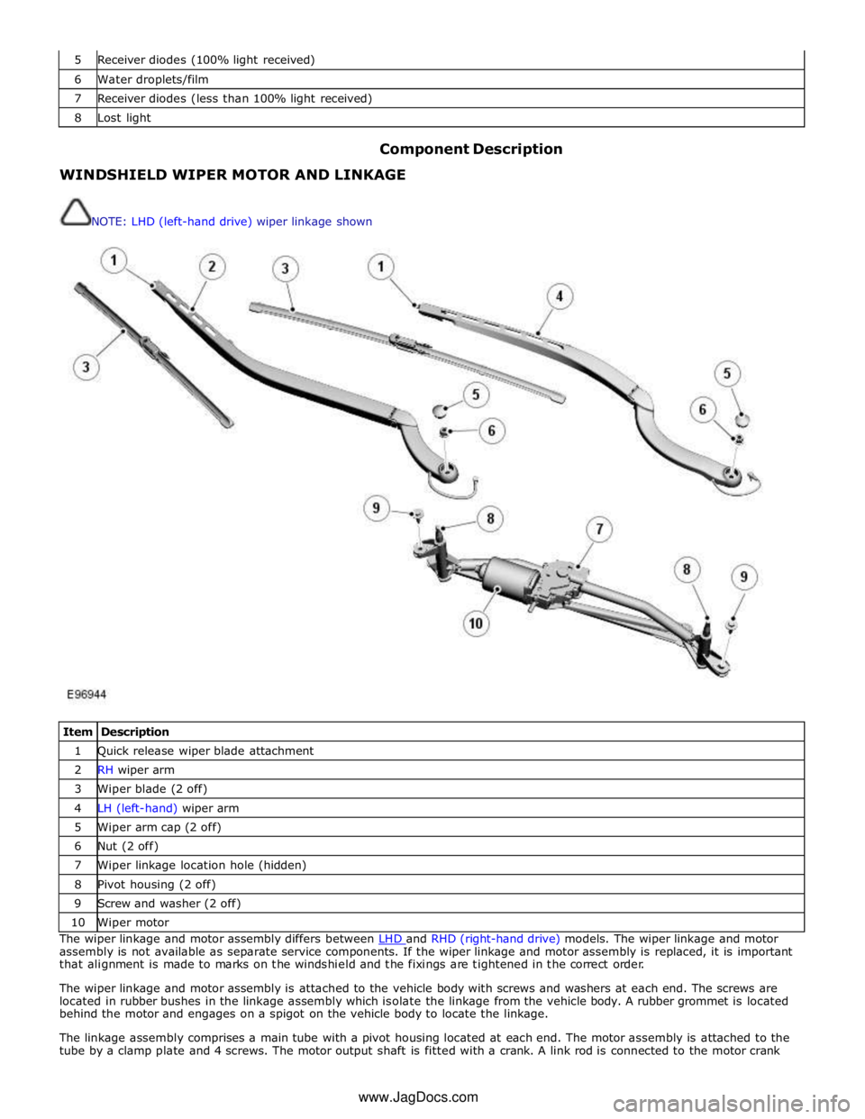
Component Description WINDSHIELD WIPER MOTOR AND LINKAGE
NOTE: LHD (left-hand drive) wiper linkage shown
Item Description 1 Quick release wiper blade attachment 2 RH wiper arm 3 Wiper blade (2 off) 4 LH (left-hand) wiper arm 5 Wiper arm cap (2 off) 6 Nut (2 off) 7 Wiper linkage location hole (hidden) 8 Pivot housing (2 off) 9 Screw and washer (2 off) 10 Wiper motor The wiper linkage and motor assembly differs between LHD and RHD (right-hand drive) models. The wiper linkage and motor assembly is not available as separate service components. If the wiper linkage and motor assembly is replaced, it is important
that alignment is made to marks on the windshield and the fixings are tightened in the correct order.
The wiper linkage and motor assembly is attached to the vehicle body with screws and washers at each end. The screws are
located in rubber bushes in the linkage assembly which isolate the linkage from the vehicle body. A rubber grommet is located
behind the motor and engages on a spigot on the vehicle body to locate the linkage.
The linkage assembly comprises a main tube with a pivot housing located at each end. The motor assembly is attached to the
tube by a clamp plate and 4 screws. The motor output shaft is fitted with a crank. A link rod is connected to the motor crank www.JagDocs.com
Page 2542 of 3039
On vehicles with headlamp powerwash, each headlamp assembly is fitted with a headlamp powerwasher. The powerwasher is
located on the underside of the headlamp assembly. The powerwasher is located in a clip at the front of the headlamp and
secured with 2 self tapping screws to the headlamp body.
The powerwasher is a telescopic unit which extends forwards from the headlamp assembly under washer fluid pressure
supplied by the headlamp powerwash pump. When the pump pressure decreases the powerwasher is automatically retracted
back into the housing. The outer end of the powerwasher is fitted with a trim which blends the powerwasher into the headlamp
when it is not operating. The powerwasher has two washer jets which direct washer fluid under high pressure onto the
headlamp lens when the powerwasher is extended.
RAIN/LIGHT SENSOR
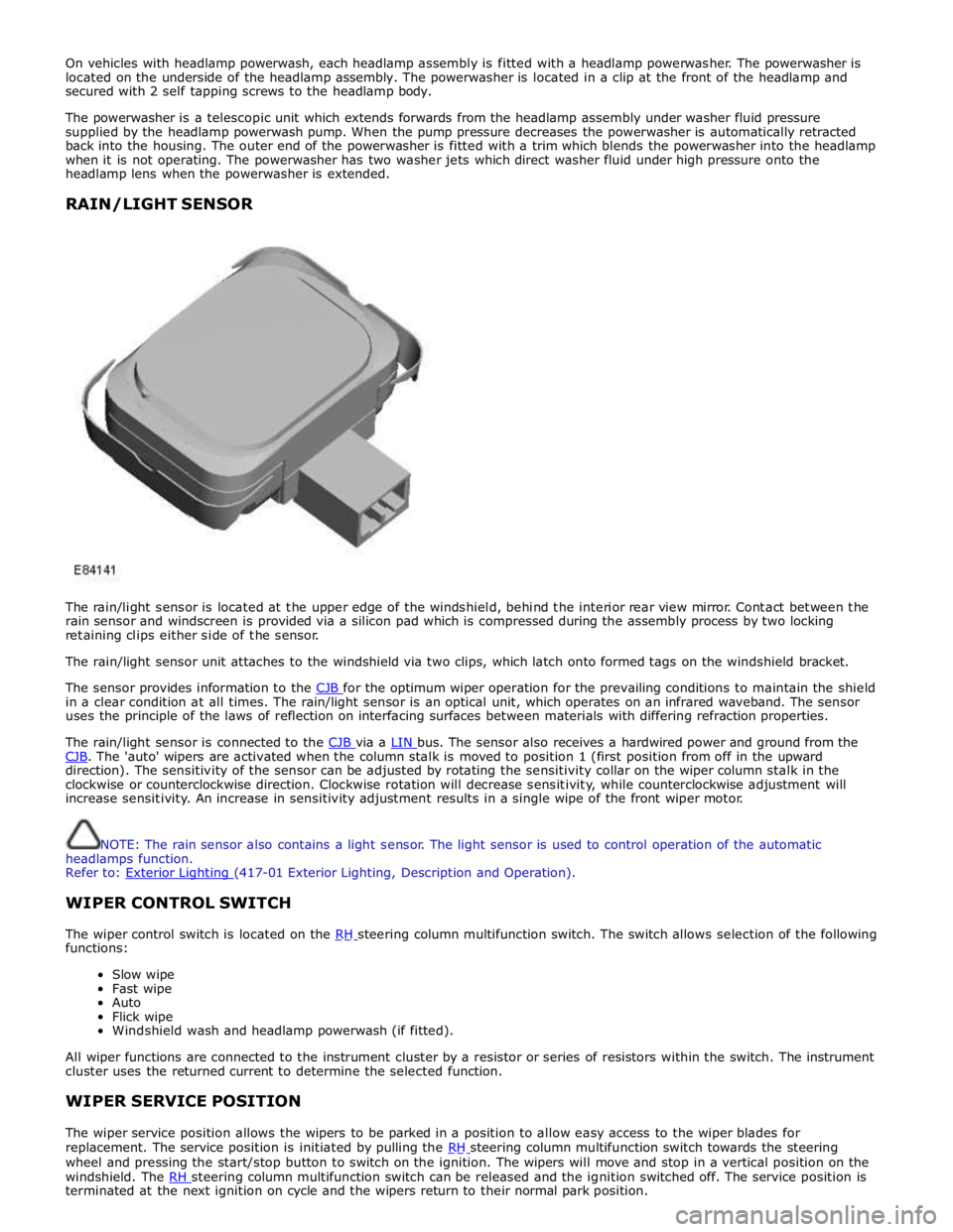
The rain/light sensor is located at the upper edge of the windshield, behind the interior rear view mirror. Contact between the
rain sensor and windscreen is provided via a silicon pad which is compressed during the assembly process by two locking
retaining clips either side of the sensor.
The rain/light sensor unit attaches to the windshield via two clips, which latch onto formed tags on the windshield bracket.
The sensor provides information to the CJB for the optimum wiper operation for the prevailing conditions to maintain the shield in a clear condition at all times. The rain/light sensor is an optical unit, which operates on an infrared waveband. The sensor
uses the principle of the laws of reflection on interfacing surfaces between materials with differing refraction properties.
The rain/light sensor is connected to the CJB via a LIN bus. The sensor also receives a hardwired power and ground from the CJB. The 'auto' wipers are activated when the column stalk is moved to position 1 (first position from off in the upward direction). The sensitivity of the sensor can be adjusted by rotating the sensitivity collar on the wiper column stalk in the
clockwise or counterclockwise direction. Clockwise rotation will decrease sensitivity, while counterclockwise adjustment will
increase sensitivity. An increase in sensitivity adjustment results in a single wipe of the front wiper motor.
NOTE: The rain sensor also contains a light sensor. The light sensor is used to control operation of the automatic
headlamps function.
Refer to: Exterior Lighting (417-01 Exterior Lighting, Description and Operation).
WIPER CONTROL SWITCH
The wiper control switch is located on the RH steering column multifunction switch. The switch allows selection of the following functions:
Slow wipe
Fast wipe
Auto
Flick wipe
Windshield wash and headlamp powerwash (if fitted).
All wiper functions are connected to the instrument cluster by a resistor or series of resistors within the switch. The instrument
cluster uses the returned current to determine the selected function.
WIPER SERVICE POSITION
The wiper service position allows the wipers to be parked in a position to allow easy access to the wiper blades for
replacement. The service position is initiated by pulling the RH steering column multifunction switch towards the steering wheel and pressing the start/stop button to switch on the ignition. The wipers will move and stop in a vertical position on the
windshield. The RH steering column multifunction switch can be released and the ignition switched off. The service position is terminated at the next ignition on cycle and the wipers return to their normal park position.
Page 2580 of 3039
Bumpers - Front Bumper
Removal and Installation Published: 11-May-2011
Removal
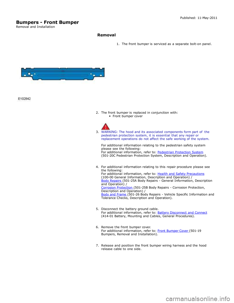
1. The front bumper is serviced as a separate bolt-on panel.
2. The front bumper is replaced in conjunction with:
Front bumper cover
3. WARNING: The hood and its associated components form part of the
pedestrian protection system, it is essential that any repair or
replacement operations do not affect the safe working of the system.
For additional information relating to the pedestrian safety system
please see the following:
For additional information, refer to: Pedestrian Protection System (501-20C Pedestrian Protection System, Description and Operation).
4. For additional information relating to this repair procedure please see
the following:
For additional information, refer to: Health and Safety Precautions (100-00 General Information, Description and Operation) /
Body Repairs (501-25A Body Repairs - General Information, Description and Operation) /
Corrosion Protection (501-25B Body Repairs - Corrosion Protection, Description and Operation) /
Body and Frame (501-26 Body Repairs - Vehicle Specific Information and Tolerance Checks, Description and Operation).
5. Disconnect the battery ground cable.
For additional information, refer to: Battery Disconnect and Connect (414-01 Battery, Mounting and Cables, General Procedures).
6. Remove the front bumper cover.
For additional information, refer to: Front Bumper Cover (501-19 Bumpers, Removal and Installation).
7. Release and position the front bumper wiring harness and the hood
release cable to one side.
Page 2625 of 3039
Supplemental Restraint System - Air Bag Disposal
General Procedures
Deployed Air Bag Published: 11-May-2011
1. WARNING: Always wear safety glasses when repairing an air bag
supplemental restraint system (SRS) vehicle and when handling an air
bag module. Failure to follow this instruction may result in personal
injury.
Deployed air bag modules are to be disposed of as special waste and
must comply with local environmental requirements, if in doubt, contact
Authority for disposal requirements.
2. NOTE: The storage, transportation, disposal, and/or recycling of air
bag module components must be carried out in accordance with all
applicable federal, state and local regulations including, but not limited
to, those governing building and fire codes, environmental protection,
occupational health and safety, and transportation.
Modules removed and deployed by Jaguar service are to be returned to
the importer for disposal.
Undeployed Air Bag — Inoperative
1. WARNING: Carry a live air bag module with the air bag and trim
cover or deployment door pointed away from your body. This will reduce
the risk of injury in the event of an accidental deployment. Failure to
follow this instruction may result in personal injury.
NOTE: All inoperative air bag modules have been placed on the
Mandatory Return List. All discolored or damaged air bag modules must
be treated the same as any inoperative live air bag being returned.
Failure to follow this instruction may result in personal injury.
Remove the inoperative driver air bag module or passenger air bag
module. For additional information Driver Air Bag Module or Passenger Air Bag Module in this section.
Remote Deployment Undeployed Air Bag — Scrapped Vehicle
1. WARNINGS:
Always wear safety glasses when repairing an air bag supplemental
restraint system (SRS) vehicle and when handling an air bag module.
Failure to follow this instruction may result in personal injury.
Carry a live air bag module with the air bag and trim cover or
deployment door pointed away from your body. This will reduce the risk
of injury in the event of an accidental deployment. Failure to follow this
instruction may result in personal injury.
Remote deployment is to be carried out outdoors with all personnel
at least 6.1 meters (20 feet) away to ensure personal safety. Due to the
loud report which occurs when the air bag is deployed, hearing protection
is required. Failure to follow this instruction may result in personal
injury.
Page 2638 of 3039
Published: 11-May-2011
Supplemental Restraint System - Occupant Classification Sensor
Removal and Installation
Removal
WARNINGS:
To avoid accidental deployment, the restraints control module backup power supply must be depleted. Wait at least one
minute after disconnecting the battery ground cable(s) before commencing any repair or adjustment to the supplemental
restraint system (SRS), or any component(s) adjacent to the SRS sensors. Failure to follow these instructions may result in
personal injury.
Always wear safety glasses when working on an air bag equipped vehicle and when handling an air bag module. Failure to
follow this instruction may result in personal injury.
To minimize the possibility of premature deployment, do not use radio key code savers when working on the
supplemental restraint system. Failure to follow this instruction may result in personal injury.
To minimize the possibility of injury in the event of premature deployment, always carry a live air bag module with the
bag and trim cover pointed away from the body. Failure to follow this instruction may result in personal injury.
To minimize the possibility of premature deployment, live air bag modules must only be placed on work benches which
have been ground bonded and with the trim cover facing up. Failure to follow these instructions may result in personal injury.
Never probe the electrical connectors of air bag modules or any other supplemental restraint system component. Failure
to follow this instruction may result in personal injury.
Painting over the driver air bag module trim cover or instrument panel could lead to deterioration of the trim cover and air
bags. Do not for any reason attempt to paint discoloured or damaged air bag module trim covers or instrument panel. Install a
new component. Failure to follow this instruction may result in personal injury.
CAUTIONS:
The front passenger seat occupant classification sensor is available only as a service kit. No attempt should be made to
replace individual components. Failure to follow this instruction may result in personal injury.
Check for correct operation of the front seat after completion of the procedure to make sure that the wiring harness has
not become trapped or stretched.
NOTES:
Note the routing of the seat harness.
Some variation in the illustrations may occur, but the essential information is always correct.
1. Make the air bag supplemental restraint system (SRS) safe.
Refer to: Standard Workshop Practices (100-00 General Information, Description and Operation).
2. Refer to: Battery Disconnect and Connect (414-01 Battery, Mounting and Cables, General Procedures).
3. Refer to: Front Seat Backrest Cover (501-10 Seating, Removal and Installation).
Page 2645 of 3039
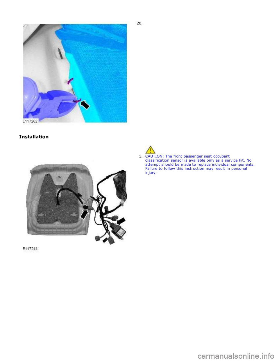
Installation 20.
1. CAUTION: The front passenger seat occupant
classification sensor is available only as a service kit. No
attempt should be made to replace individual components.
Failure to follow this instruction may result in personal
injury.