2010 JAGUAR XFR service
[x] Cancel search: servicePage 1868 of 3039
Any actions must be carried out in accordance with the table shown in the Determining Battery Condition section (Section 6)
of this procedure. The details must be recorded on the New Vehicle Storage Form which is part of the new vehicle storage
document.
For additional information, refer to: New Vehicle Storage Form (100-11 Vehicle Transportation Aids and Vehicle Storage, Description and Operation).
4.3 PDI / DELIVERY TO CUSTOMER
Before the vehicle is handed over to the customer and as part of the PDI, the condition of the battery needs to be confirmed.
The battery condition must be checked in accordance with the battery test process utilizing a JLR approved tester as outlined
in the Equipment section (Section 5) of this procedure.
NOTE: The Midtronics code from the tester must be recorded on the form.
Any actions must be carried out in accordance with the table shown in the Determining Battery Condition section (Section 6)
of this procedure. The details must be recorded on the New Vehicle Storage Form which is part of the new vehicle storage
document.
For additional information, refer to: New Vehicle Storage Form (100-11 Vehicle Transportation Aids and Vehicle Storage, Description and Operation).
4.4 REPLACEMENT BATTERIES FOR SERVICE
All service replacement batteries must have the battery condition checked within 24 hours of receipt and controlled on a ‘First
In First Out’ basis to ensure batteries are not allowed to age unnecessarily.
For batteries in storage and not yet fitted to a vehicle, they must be stored in a dry environment, not in direct sunlight or
under any direct heat source. Any batteries exhibiting any forms of damage or corrosion must not be fitted to any vehicle. Any
batteries which are dropped must be scrapped, this applies even if no external damage is apparent.
The battery condition must be checked every 30 days in accordance with the battery test process utilizing a JLR approved
tester as outlined in the Equipment section (Section 5) of this procedure.
Any actions must be carried out in accordance with the table shown in the Determining Battery Condition section (Section 6)
of this procedure.The details must be recorded on the New Vehicle Storage Form which is part of the new vehicle storage
document.
For additional information, refer to: New Vehicle Storage Form (100-11 Vehicle Transportation Aids and Vehicle Storage, Description and Operation).
4.5 BATTERY MAINTENANCE
Any battery whether it is in a vehicle or a replacement part must be tested and/or re-charged every 30 days and MUST be
re-charged after every 90 day period.
4.6 BATTERY TEST PROCESS
It is recommended that this test is conducted at least 24 hours after the vehicle engine has been run or the battery charged to
avoid the need of surface charge removal. If time constraints make this unacceptable then the surface charge must be
removed.
Surface Charge Removal
A vehicle which has had its battery charged or been driven in a 24 hour period before the test, must have its surface charge
removed.
Turn on the ignition (power mode 6) but do not start the vehicle
Switch on the headlamps on high beam for a minimum 3 minutes
Switch off the headlamps
Wait a minimum of 5 minutes before recording test results for any battery measurements
Battery Test
The battery may be tested either on a bench or on the vehicle.
The battery condition must be checked in accordance with the battery test process utilizing a JLR approved tester as outlined
in the Equipment section (Section 5) of this procedure.
NOTE: The Midtronics code from the tester must be recorded on the form.
Any actions must be carried out in accordance with the table shown in the Determining Battery Condition section (Section 6)
of this procedure. The details must be recorded on the New Vehicle Storage Form which is part of the new vehicle storage
document.
For additional information, refer to: New Vehicle Storage Form (100-11 Vehicle Transportation Aids and Vehicle Storage, Description and Operation).
CAUTION: DO NOT connect the tester to any other circuit or chassis point other than the battery negative terminal.
Page 1869 of 3039
5. EQUIPMENT
All equipment used must be functionally capable of meeting the compliance requirements. Please refer to the approved
equipment document (JLR 000015).
In the case of batteries fitted to a new vehicle at the dealership, battery condition should be measured using the appropriate
hand-held Midtronics tester as follows:
Battery Type Battery Tester Battery Tester Jaguar Land Rover AGM & Flooded Midtronics EXP1080, GRX 3080 Midtronics EXP1080, GRX 3080 The test results must be recorded on the New Vehicle Storage Form which is part of the new vehicle storage document.
For additional information, refer to: New Vehicle Storage Form (100-11 Vehicle Transportation Aids and Vehicle Storage, Description and Operation).
NOTE: All equipment must be calibrated
6 DETERMINING BATTERY CONDITION
TESTER RESULTS ACTION GOOD BATTERY Return to service. GOOD RE-CHARGE Fully charge battery and return to service. CHARGE AND RE-TEST Fully charge battery. Remove surface charge. Re-test battery. If same result replace battery. REPLACE BATTERY OR BAD
CELL BATTERY Verify surface charge removed. Disconnect battery from vehicle and re-test. If result repeats after
surface charge removal, replace battery. DO NOT RECHARGE. UNABLE TO DO TEST Disconnect battery from vehicle and re-test. 7 BATTERY CHARGING
It is essential that a suitably ventilated defined area exists in each dealership / retailer for battery charging.
CAUTION: It is very important that when charging batteries using the traction charger or other stand-alone chargers that
the charger is set for the correct type of battery before charging commences. If the wrong switch is selected the result would
be a battery that is not charged fully and / or overheating can occur. Follow the manufacturers operating instructions.
Batteries MUST BE tested and if necessary charged every 30 days and charged after 90 days irrespective of any test. It is
recommended that dealers / retailers always have fully charged batteries ready for use.
CAUTION: Do not charge AGM batteries with voltages over 14.8 Volts as this will damage the battery.
A designated controlled area must be allocated for scrap batteries and clearly controlled as such.
To bring a discharged but serviceable battery back to a fully charged condition proceed as follows:
Check and if necessary top-up the battery electrolyte level. (Flooded maintainable batteries only)
Charge the battery using a JLR approved charger as detailed in the approved equipment document following the
manufacturers operating instructions.
NOTE: When using the Midtronics Diagnostic Charger, automatic mode must always be used. After charging and analysis,
the charger may display ‘Top-Off Charging’, Hit STOP To End. Do not stop charging until the current falls to 5A or less,
otherwise the battery will not be fully charged.
Following charging, a post charge battery condition test must be carried out in accordance with the table shown in the
Determining Battery Condition section (Section 6) of this procedure.
NOTE: The Midtronics code from the tester must be recorded on the form.
Any actions must be carried out in accordance with the table shown in the Determining Battery Condition section (Section 6)
of this procedure. The details must be recorded on the New Vehicle Storage Form which is part of the new vehicle storage
document.
For additional information, refer to: New Vehicle Storage Form (100-11 Vehicle Transportation Aids and Vehicle Storage, Description and Operation).
8 BATTERY REPLACEMENT
If it is determined that a battery requires replacement, always refer to the appropriate section of the workshop manual for
instructions on removing and installing the battery from the vehicle.
On in service vehicles fitted with a Battery Monitoring System (BMS), the BMS control module must be reset following the
installation of a new battery. The BMS control module reset procedure must be performed using an approved diagnostic
Page 1873 of 3039
Published: 02-Apr-2014
Battery and Charging System - General Information - Battery Report Form – In Service Batteries Only
Description and Operation
NOTE: Fields marked with * are mandatory and must be completed.
General Information *Vehicle Identification Number (VIN):
Vehicle
Model: Engine type: *Mileage:
*Repair
Date: - Customer Questions *1: What is the customer’s reason for dealer visit? (tick symptoms as appropriate) Non crank
Crank but non
start Warning message Other: *2: How long was the vehicle left prior to issue. * *3: How was the car left (Locked/unlocked) * *4: How did you access to the vehicle Key fob Manual key Handle pull *5: Has the vehicle required assistance for battery issues previously? Yes No *6: Is the vehicle used? (tick symptoms as appropriate) Daily
Every other day Weekly
Less than weekly *7: Average journey length * *8: How many starts do you typically do in a day * *9: Did the customer see any instrument pack warnings prior to the
issue? * *10: Have any of the features been used
without the engine running in the last 3 days (if fitted?) Radio
Power point
accessory CD DVD USB or IPOD
connection TV
Rear seat
entertainment 11: Customer comments:- Please add any additional comments that
are relevant. * Diagnostics (Battery Testing) - - - - 1: Loose battery clamps Yes * No * 2: Loose hold down clamps Yes * No * 3: Corroded terminal posts Yes * No * 4: Physical damage/leaks Yes No * 5: Low electrolyte (Flooded batteries only) Yes * No * 6: Battery Date Code * 7: FEAD belt tension OK * Not OK * 8: Quiescent Drain mA * 9: Vent tube correctly installed Yes * No * 10: Number of Times Battery Charged: * 10: Vent tube correctly installed Yes No 11: Remove the Surface (414-00 battery care requirements) Yes * No * 12: Battery voltage * 13: Midtronics test code before charging (EXP-1080) * 13a: If Midtronics indicates that the battery needs re-charging, charge
the battery following instructions on the recommended battery charger * 13b: Midtronics test code after charge * 13c: Midtronics test code result after charge * 13d: If "good and re-charge" charge the battery following instructions
on the recommended battery charger * 13e: If "charge and re-test" for both before and after the charge
renew the battery * 13f: Only renew the battery if "renew battery", "bad cell" or charge
and re-test has been displayed twice. * Technician Comments:- Please add any additional comments that are relevant. * * * * *
Page 1892 of 3039
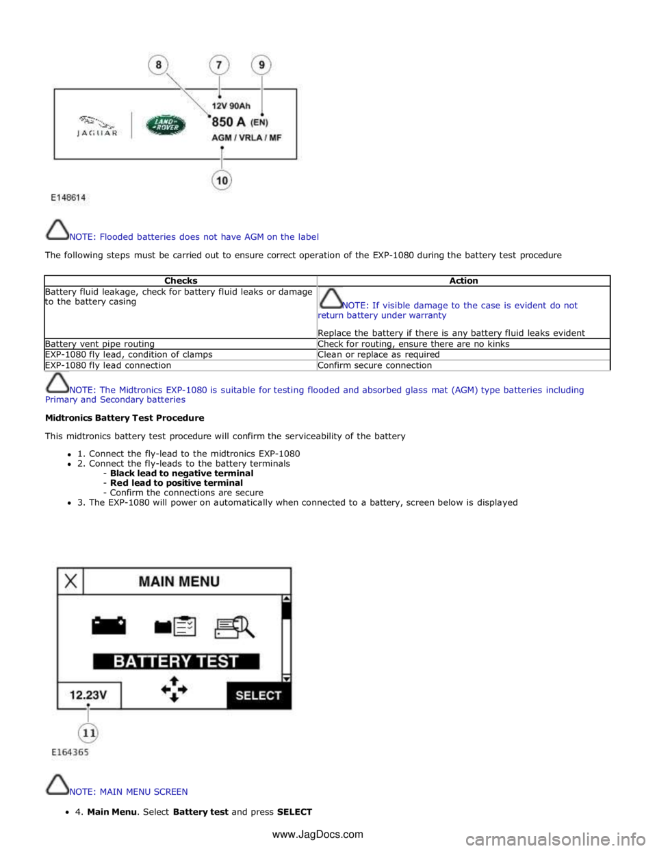
NOTE: Flooded batteries does not have AGM on the label
The following steps must be carried out to ensure correct operation of the EXP-1080 during the battery test procedure
Checks Action Battery fluid leakage, check for battery fluid leaks or damage
to the battery casing
NOTE: If visible damage to the case is evident do not
return battery under warranty
Replace the battery if there is any battery fluid leaks evident Battery vent pipe routing Check for routing, ensure there are no kinks EXP-1080 fly lead, condition of clamps Clean or replace as required EXP-1080 fly lead connection Confirm secure connection
NOTE: The Midtronics EXP-1080 is suitable for testing flooded and absorbed glass mat (AGM) type batteries including
Primary and Secondary batteries
Midtronics Battery Test Procedure
This midtronics battery test procedure will confirm the serviceability of the battery
1. Connect the fly-lead to the midtronics EXP-1080
2. Connect the fly-leads to the battery terminals
- Black lead to negative terminal
- Red lead to positive terminal
- Confirm the connections are secure
3. The EXP-1080 will power on automatically when connected to a battery, screen below is displayed
NOTE: MAIN MENU SCREEN 4.MainMenu.SelectBatterytestandpressSELECT
www.JagDocs.com
Page 1896 of 3039
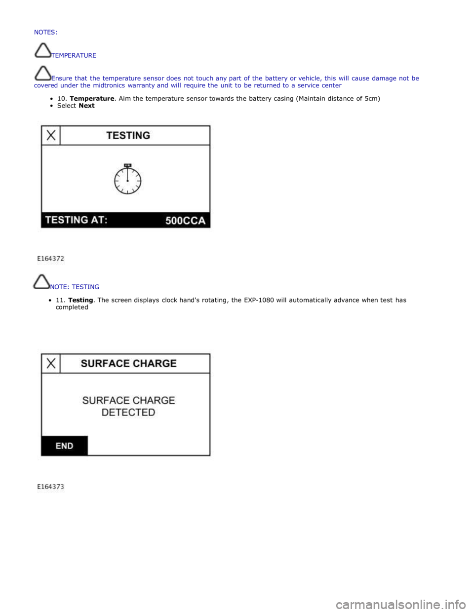
NOTE:
TESTING
11.
Testing.
The
screen
displays
clock
hand's
rotating,
the
EXP-1080
will
automatically
advance
when
test
has
completed
NOTES:
TEMPERATURE
Ensurethatthetemperaturesensordoesnottouchanypartofthebatteryorvehicle,thiswillcausedamagenotbe
coveredunderthemidtronicswarrantyand willrequiretheunittobereturnedtoaservicecenter
10.Temperature.Aimthetemperaturesensortowardsthebatterycasing (Maintaindistanceof5cm)
SelectNext
Page 1915 of 3039
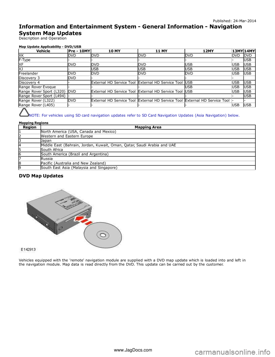
Published: 24-Mar-2014
Information and Entertainment System - General Information - Navigation
System Map Updates
Description and Operation
Map Update Applicability - DVD/USB
Vehicle Pre - 10MY 10 MY 11 MY 12MY 13MY 14MY XK DVD DVD DVD DVD DVD DVD F-Type - - - - - USB XF DVD DVD DVD USB USB USB XJ - USB USB USB USB USB Freelander DVD DVD DVD DVD USB USB Discovery 3 DVD - - - - Discovery 4 - External HD Service Tool External HD Service Tool USB USB USB Range Rover Evoque - - - USB USB USB Range Rover Sport (L320) DVD External HD Service Tool External HD Service Tool USB USB USB Range Rover Sport (L494) - - - - - USB Range Rover (L322) DVD External HD Service Tool External HD Service Tool External HD Service Tool - - Range Rover (L405) - - - - USB USB
NOTE: For vehicles using SD card navigation updates refer to SD Card Navigation Updates (Asia Navigation) below.
Mapping Regions
Region Mapping Area 1 North America (USA, Canada and Mexico) 2 Western and Eastern Europe 3 Japan 4 Middle East (Bahrain, Jordan, Kuwait, Oman, Qatar, Saudi Arabia and UAE 5 South Africa 6 South America (Brazil and Argentina) 7 Russia 8 Pacific (Australia and New Zealand) 9 South East Asia (Malaysia and Singapore)
DVD Map Updates
Vehicles equipped with the 'remote' navigation module are supplied with a DVD map update which is loaded into and left in
the navigation module. Map data is read directly from the DVD. This update can be carried out by the customer. www.JagDocs.com
Page 1916 of 3039
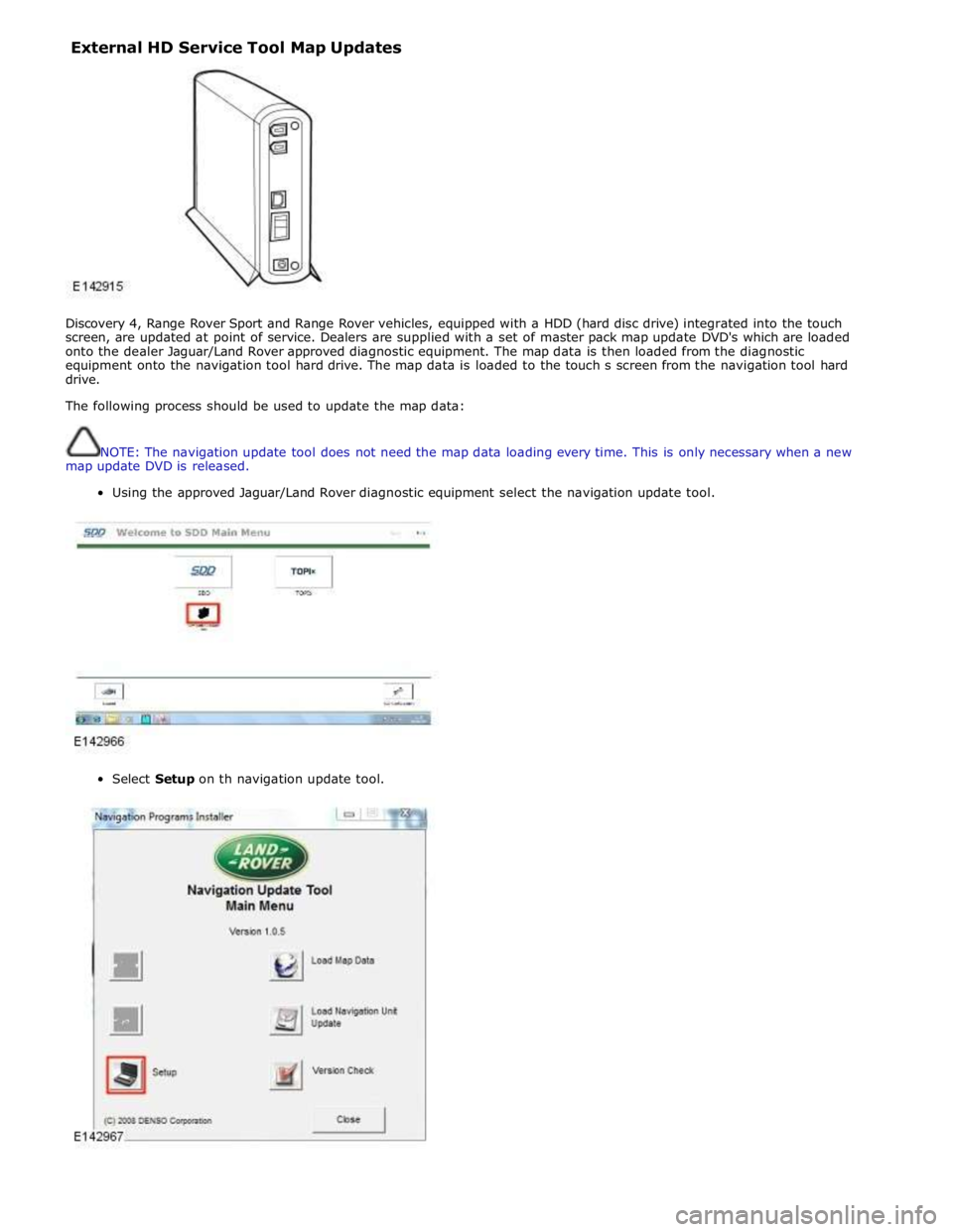
External HD Service Tool Map Updates
Discovery 4, Range Rover Sport and Range Rover vehicles, equipped with a HDD (hard disc drive) integrated into the touch
screen, are updated at point of service. Dealers are supplied with a set of master pack map update DVD's which are loaded
onto the dealer Jaguar/Land Rover approved diagnostic equipment. The map data is then loaded from the diagnostic
equipment onto the navigation tool hard drive. The map data is loaded to the touch s screen from the navigation tool hard
drive.
The following process should be used to update the map data:
NOTE: The navigation update tool does not need the map data loading every time. This is only necessary when a new
map update DVD is released.
Using the approved Jaguar/Land Rover diagnostic equipment select the navigation update tool.
Select Setup on th navigation update tool.
Page 1935 of 3039
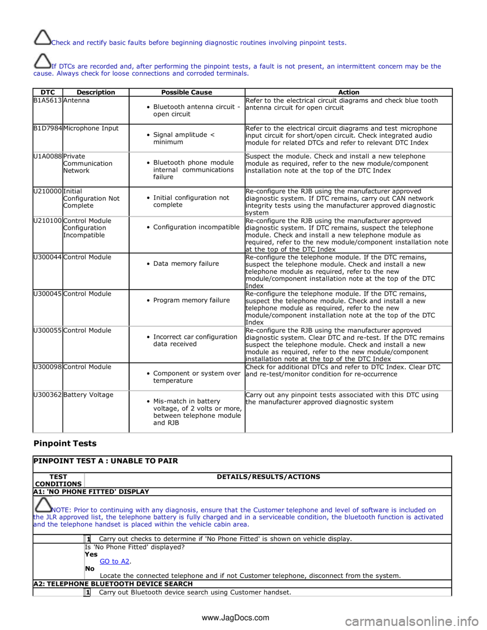
Check and rectify basic faults before beginning diagnostic routines involving pinpoint tests.
If DTCs are recorded and, after performing the pinpoint tests, a fault is not present, an intermittent concern may be the
cause. Always check for loose connections and corroded terminals.
DTC Description Possible Cause Action B1A5613 Antenna
Bluetooth antenna circuit -
open circuit Refer to the electrical circuit diagrams and check blue tooth
antenna circuit for open circuit B1D7984 Microphone Input
Signal amplitude <
minimum Refer to the electrical circuit diagrams and test microphone
input circuit for short/open circuit. Check integrated audio
module for related DTCs and refer to relevant DTC Index U1A0088
Private
Communication
Network
Bluetooth phone module
internal communications
failure Suspect the module. Check and install a new telephone
module as required, refer to the new module/component
installation note at the top of the DTC Index U210000
Initial
Configuration Not
Complete
Initial configuration not
complete Re-configure the RJB using the manufacturer approved
diagnostic system. If DTC remains, carry out CAN network
integrity tests using the manufacturer approved diagnostic system U210100
Control Module
Configuration
Incompatible
Configuration incompatible Re-configure the RJB using the manufacturer approved
diagnostic system. If DTC remains, suspect the telephone
module. Check and install a new telephone module as
required, refer to the new module/component installation note
at the top of the DTC Index U300044 Control Module
Data memory failure Re-configure the telephone module. If the DTC remains,
suspect the telephone module. Check and install a new
telephone module as required, refer to the new
module/component installation note at the top of the DTC
Index U300045 Control Module
Program memory failure Re-configure the telephone module. If the DTC remains,
suspect the telephone module. Check and install a new
telephone module as required, refer to the new
module/component installation note at the top of the DTC
Index U300055 Control Module
Incorrect car configuration
data received Re-configure the RJB using the manufacturer approved
diagnostic system. Clear DTC and re-test. If the DTC remains
suspect the telephone module. Check and install a new
module as required, refer to the new module/component
installation note at the top of the DTC Index U300098 Control Module
Component or system over
temperature Check for additional DTCs and refer to DTC Index. Clear DTC
and re-test/monitor condition for re-occurrence U300362 Battery Voltage
Mis-match in battery
voltage, of 2 volts or more,
between telephone module
and RJB Carry out any pinpoint tests associated with this DTC using
the manufacturer approved diagnostic system
Pinpoint Tests
PINPOINT TEST A : UNABLE TO PAIR TEST
CONDITIONS DETAILS/RESULTS/ACTIONS A1: 'NO PHONE FITTED' DISPLAY
NOTE: Prior to continuing with any diagnosis, ensure that the Customer telephone and level of software is included on
the JLR approved list, the telephone battery is fully charged and in a serviceable condition, the bluetooth function is activated
and the telephone handset is placed within the vehicle cabin area. 1 Carry out checks to determine if 'No Phone Fitted' is shown on vehicle display. Is 'No Phone Fitted' displayed? Yes
GO to A2. No
Locate the connected telephone and if not Customer telephone, disconnect from the system. A2: TELEPHONE BLUETOOTH DEVICE SEARCH 1 Carry out Bluetooth device search using Customer handset. www.JagDocs.com