2010 JAGUAR XFR service
[x] Cancel search: servicePage 1276 of 3039
Published: 11-May-2011
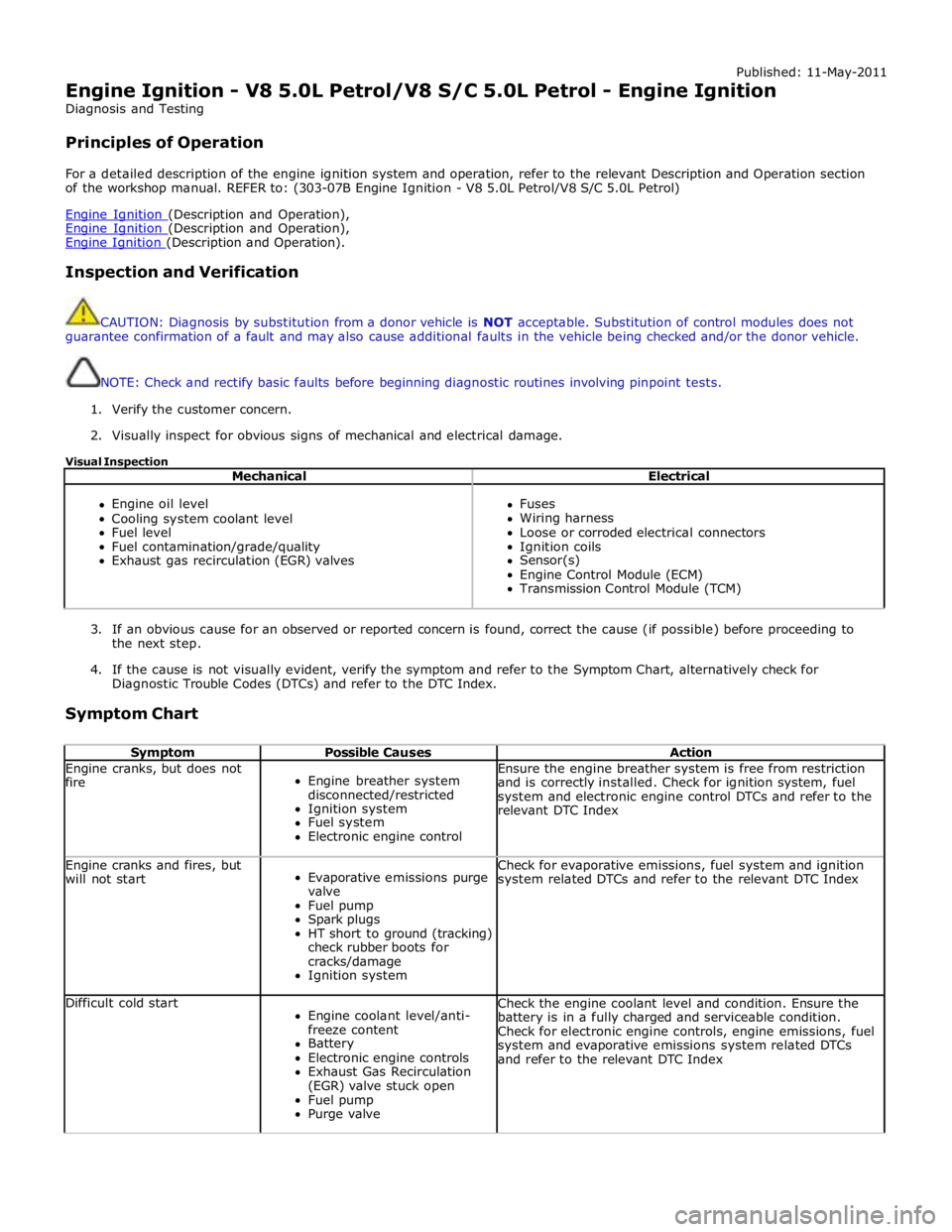
Engine Ignition - V8 5.0L Petrol/V8 S/C 5.0L Petrol - Engine Ignition
Diagnosis and Testing
Principles of Operation
For a detailed description of the engine ignition system and operation, refer to the relevant Description and Operation section
of the workshop manual. REFER to: (303-07B Engine Ignition - V8 5.0L Petrol/V8 S/C 5.0L Petrol)
Engine Ignition (Description and Operation), Engine Ignition (Description and Operation), Engine Ignition (Description and Operation).
Inspection and Verification
CAUTION: Diagnosis by substitution from a donor vehicle is NOT acceptable. Substitution of control modules does not
guarantee confirmation of a fault and may also cause additional faults in the vehicle being checked and/or the donor vehicle.
NOTE: Check and rectify basic faults before beginning diagnostic routines involving pinpoint tests.
1. Verify the customer concern.
2. Visually inspect for obvious signs of mechanical and electrical damage.
Visual Inspection
Mechanical Electrical
Engine oil level
Cooling system coolant level
Fuel level
Fuel contamination/grade/quality
Exhaust gas recirculation (EGR) valves
Fuses
Wiring harness
Loose or corroded electrical connectors
Ignition coils
Sensor(s)
Engine Control Module (ECM)
Transmission Control Module (TCM)
3. If an obvious cause for an observed or reported concern is found, correct the cause (if possible) before proceeding to
the next step.
4. If the cause is not visually evident, verify the symptom and refer to the Symptom Chart, alternatively check for
Diagnostic Trouble Codes (DTCs) and refer to the DTC Index.
Symptom Chart
Symptom Possible Causes Action Engine cranks, but does not
fire
Engine breather system
disconnected/restricted
Ignition system
Fuel system
Electronic engine control Ensure the engine breather system is free from restriction
and is correctly installed. Check for ignition system, fuel
system and electronic engine control DTCs and refer to the
relevant DTC Index Engine cranks and fires, but
will not start
Evaporative emissions purge
valve
Fuel pump
Spark plugs
HT short to ground (tracking)
check rubber boots for
cracks/damage
Ignition system Check for evaporative emissions, fuel system and ignition
system related DTCs and refer to the relevant DTC Index Difficult cold start
Engine coolant level/anti-
freeze content
Battery
Electronic engine controls
Exhaust Gas Recirculation
(EGR) valve stuck open
Fuel pump
Purge valve Check the engine coolant level and condition. Ensure the
battery is in a fully charged and serviceable condition.
Check for electronic engine controls, engine emissions, fuel
system and evaporative emissions system related DTCs
and refer to the relevant DTC Index
Page 1369 of 3039
Published: 16-Sep-2013
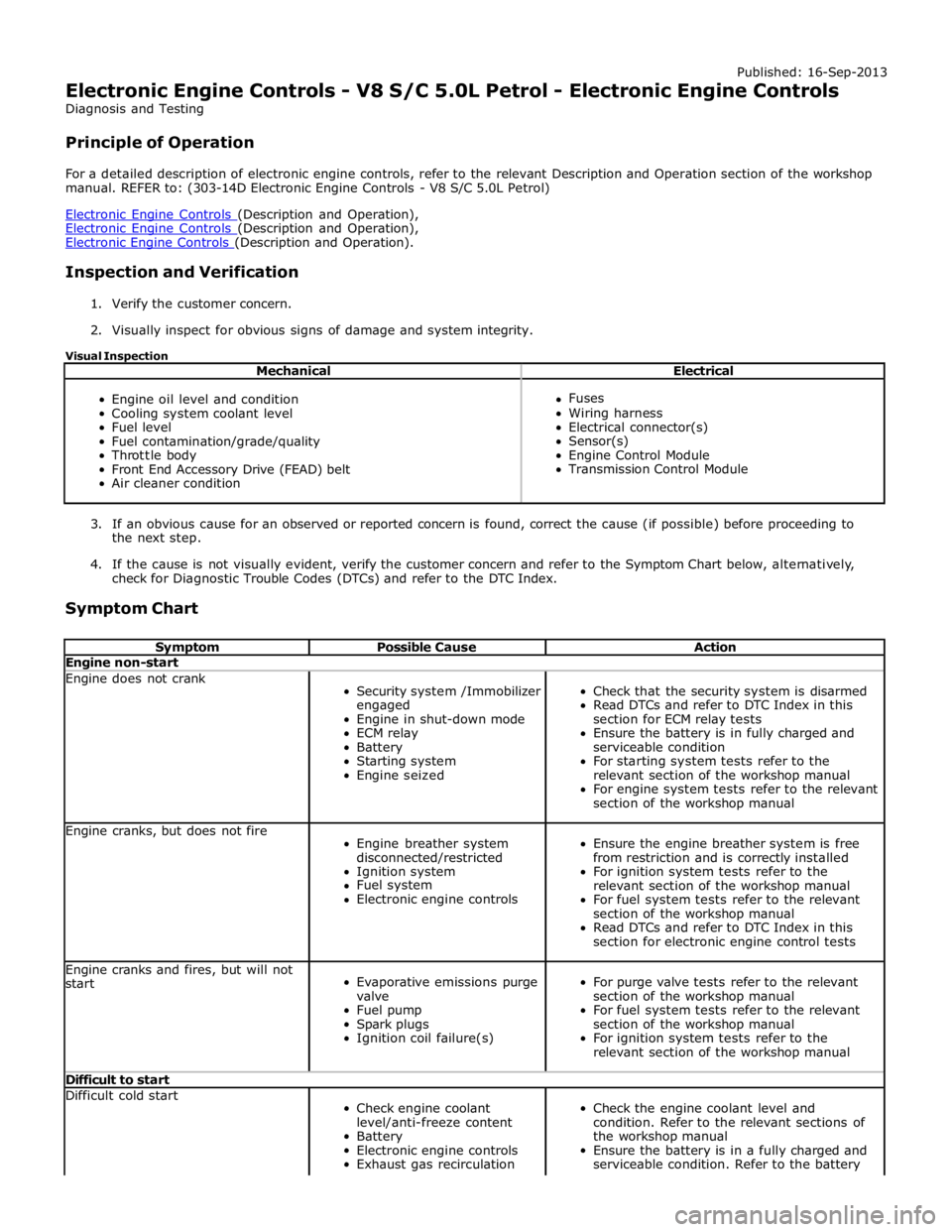
Electronic Engine Controls - V8 S/C 5.0L Petrol - Electronic Engine Controls
Diagnosis and Testing
Principle of Operation
For a detailed description of electronic engine controls, refer to the relevant Description and Operation section of the workshop
manual. REFER to: (303-14D Electronic Engine Controls - V8 S/C 5.0L Petrol)
Electronic Engine Controls (Description and Operation), Electronic Engine Controls (Description and Operation), Electronic Engine Controls (Description and Operation).
Inspection and Verification
1. Verify the customer concern.
2. Visually inspect for obvious signs of damage and system integrity.
Visual Inspection
Mechanical Electrical
Engine oil level and condition
Cooling system coolant level
Fuel level
Fuel contamination/grade/quality
Throttle body
Front End Accessory Drive (FEAD) belt
Air cleaner condition
Fuses
Wiring harness
Electrical connector(s)
Sensor(s)
Engine Control Module
Transmission Control Module
3. If an obvious cause for an observed or reported concern is found, correct the cause (if possible) before proceeding to
the next step.
4. If the cause is not visually evident, verify the customer concern and refer to the Symptom Chart below, alternatively,
check for Diagnostic Trouble Codes (DTCs) and refer to the DTC Index.
Symptom Chart
Symptom Possible Cause Action Engine non-start Engine does not crank
Security system /Immobilizer
engaged
Engine in shut-down mode
ECM relay
Battery
Starting system
Engine seized
Check that the security system is disarmed
Read DTCs and refer to DTC Index in this
section for ECM relay tests
Ensure the battery is in fully charged and
serviceable condition
For starting system tests refer to the
relevant section of the workshop manual
For engine system tests refer to the relevant
section of the workshop manual Engine cranks, but does not fire
Engine breather system
disconnected/restricted
Ignition system
Fuel system
Electronic engine controls
Ensure the engine breather system is free
from restriction and is correctly installed
For ignition system tests refer to the
relevant section of the workshop manual
For fuel system tests refer to the relevant
section of the workshop manual
Read DTCs and refer to DTC Index in this
section for electronic engine control tests Engine cranks and fires, but will not
start
Evaporative emissions purge
valve
Fuel pump
Spark plugs
Ignition coil failure(s)
For purge valve tests refer to the relevant
section of the workshop manual
For fuel system tests refer to the relevant
section of the workshop manual
For ignition system tests refer to the
relevant section of the workshop manual Difficult to start Difficult cold start
Check engine coolant
level/anti-freeze content
Battery
Electronic engine controls
Exhaust gas recirculation
Check the engine coolant level and
condition. Refer to the relevant sections of
the workshop manual
Ensure the battery is in a fully charged and
serviceable condition. Refer to the battery
Page 1370 of 3039

Symptom Possible Cause Action (EGR) valve stuck open
Fuel pump
Evaporative emissions purge
valve care manual and the relevant sections of the
workshop manual.
Read DTCs and refer to DTC Index in this
section for electronic engine control tests
Refer to the relevant section of the
workshop manual and check the Exhaust Gas
Recirculation (EGR) valve and associated
hoses and connections.
For fuel system tests refer to the relevant
section of the workshop manual
Refer to the relevant section of the
workshop manual and check the purge valve
and associated hoses and connections. Difficult hot start
Injector leak
Electronic engine controls
Evaporative emissions purge
valve
Fuel pump
Ignition system
EGR valve stuck open
Refer to the relevant section of the
workshop manual, carry out injector leak
tests, install new injectors as necessary.
Read DTCs and refer to DTC Index in this
section for electronic engine control tests
Refer to the relevant section of the
workshop manual and check the purge valve
and associated hoses and connections.
For fuel system tests refer to the relevant
section of the workshop manual
For ignition system tests refer to the
relevant section of the workshop manual
Refer to the relevant section of the
workshop manual and check the Exhaust Gas
Recirculation (EGR) valve and associated
hoses and connections. Difficult to start after hot soak
(vehicle standing, engine off, after
engine has reached operating
temperature)
Injector leak
Electronic engine controls
Evaporative emissions purge
valve
Fuel pump
Ignition system
EGR valve stuck open
Refer to the relevant section of the
workshop manual, carry out injector leak
tests, install new injectors as necessary.
Read DTCs and refer to DTC Index in this
section for electronic engine control tests
Refer to the relevant section of the
workshop manual and check the purge valve
and associated hoses and connections.
For fuel system tests refer to the relevant
section of the workshop manual
For ignition system tests refer to the
relevant section of the workshop manual
Refer to the relevant section of the
workshop manual and check the Exhaust Gas
Recirculation (EGR) valve and associated
hoses and connections. Engine cranks too fast/slow
Compressions high/low
Battery
Starting system
Refer to the relevant section of the
workshop manual, carry out compression
tests.
Ensure the battery is in a fully charged and
serviceable condition. Refer to the battery
care manual and the relevant sections of the
workshop manual.
For starting system tests refer to the
relevant section of the workshop manual Engine stalls Engine stalls soon after start
Breather system
disconnected/restricted
ECM relay
Electronic engine controls
Ignition system
Air intake system restricted
Air leakage
Fuel lines
Ensure the engine breather system is free
from restriction and is correctly installed
Read DTCs and refer to DTC Index in this
section for ECM relay tests
Read DTCs and refer to DTC Index in this
section for electronic engine control tests
For ignition system tests refer to the
relevant section of the workshop manual
Check for blockage in air cleaner element
and air intake system
Check for leakage in air intake system
For fuel system tests refer to the relevant
section of the workshop manual
Page 1423 of 3039

The TCM can be reprogrammed using a Jaguar approved diagnostic system using a flash code. The TCM processor has a 440 kb internal flash memory. Of this capacity, approximately 370 kb are used by the basic transmission program. The remainder,
approximately 70 kb is used to store vehicle-specific application data.
Engine Stall
If the vehicle stalls it will coast down in gear, with the transmission providing drive to the engine. A restart can be attempted
at this point and the engine may start and the driver can continue.
If the coast down speed reduces such that the speed of the engine is less than 600 rev/min, the transmission will go to
neutral, D illumination will flash in the instrument cluster. The driver needs to select neutral or park and then press the brake
pedal to restart the engine.
If the start/stop button is pressed when driving, the message ENGINE STOP BUTTON PRESSED is displayed in the message
center but there will be no change to the ignition state. If the driver requires to switch off the engine, the start/stop button
must be pressed for a second time. The engine will be stopped and will be back driven by the transmission as the vehicle
coasts down. When the engine speed is less than 600 rev/min the transmission engages neutral (flashing D illumination in the
instrument cluster). When vehicle speed is less than 2 km/h (1.2 mph) Park is engaged. The JaguarDrive selector automatically
rotates back to its lowered P position and the vehicle ignition is switched off.
The park engagement is prevented in a stall case as the ignition power is on and D was the last selected gear. The park
engagement speed at ignition off is from the least value of the wheel speeds (CAN signal) and transmission output speed (internal signal).
TRANSMISSION Component Description
The transmission comprises the main casing which houses all of the transmission components. The main casing also
incorporates an integral bell housing.
A fluid pan is attached to the lower face of the main casing and is secured with bolts. The fluid pan is sealed to the main
casing with a gasket. Removal of the fluid pan allows access to the Mechatronic valve block. The fluid pan has a magnet
located around the drain plug which collects any metallic particles present in the transmission fluid.
A fluid filter is located inside the fluid pan. If the transmission fluid becomes contaminated or after any service work, the fluid
pan with integral filter must be replaced.
The integral bell housing provides protection for the torque converter assembly and also provides the attachment for the
gearbox to the engine cylinder block. The torque converter is a non-serviceable assembly which also contains the lock-up clutch
mechanism. The torque converter drives a crescent type pump via drive tangs. The fluid pump is located in the main casing,
behind the torque converter.
The main casing contains the following major components:
Input shaft
Output shaft
Mechatronic valve block which contains the solenoids, speed sensors and the TCM Three rotating multiplate drive clutches
Two fixed multiplate brake clutches
A single planetary gear train and a double planetary gear train.
Page 1431 of 3039
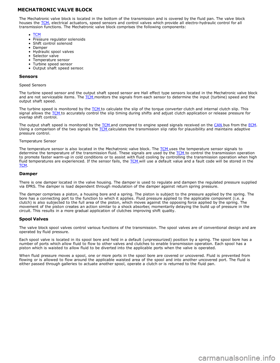
transmission functions. The Mechatronic valve block comprises the following components:
TCM
Pressure regulator solenoids
Shift control solenoid
Damper
Hydraulic spool valves
Selector valve
Temperature sensor
Turbine speed sensor
Output shaft speed sensor.
Sensors
Speed Sensors
The turbine speed sensor and the output shaft speed sensor are Hall effect type sensors located in the Mechatronic valve block
and are not serviceable items. The TCM monitors the signals from each sensor to determine the input (turbine) speed and the output shaft speed.
The turbine speed is monitored by the TCM to calculate the slip of the torque converter clutch and internal clutch slip. This signal allows the TCM to accurately control the slip timing during shifts and adjust clutch application or release pressure for overlap shift control.
The output shaft speed is monitored by the TCM and compared to engine speed signals received on the CAN bus from the ECM. Using a comparison of the two signals the TCM calculates the transmission slip ratio for plausibility and maintains adaptive pressure control.
Temperature Sensor
The temperature sensor is also located in the Mechatronic valve block. The TCM uses the temperature sensor signals to determine the temperature of the transmission fluid. These signals are used by the TCM to control the transmission operation to promote faster warm-up in cold conditions or to assist with fluid cooling by controlling the transmission operation when high
fluid temperatures are experienced. If the sensor fails, the TCM will use a default value and a fault code will be stored in the TCM.
Damper
There is one damper located in the valve housing. The damper is used to regulate and dampen the regulated pressure supplied
via EPRS. The damper is load dependent through modulation of the damper against return spring pressure.
The damper comprises a piston, a housing bore and a spring. The piston is subject to the pressure applied by the spring. The
bore has a connecting port to the function to which it applies. Fluid pressure applied to the applicable component (i.e. a
clutch) is also subjected to the full area of the piston, which moves against the opposing force applied by the spring. The
movement of the piston creates an action similar to a shock absorber, momentarily delaying the build up of pressure in the
circuit. This results in a more gradual application of clutches improving shift quality.
Spool Valves
The valve block spool valves control various functions of the transmission. The spool valves are of conventional design and are
operated by fluid pressure.
Each spool valve is located in its spool bore and held in a default (unpressurized) position by a spring. The spool bore has a
number of ports which allow fluid to flow to other valves and clutches to enable transmission operation. Each spool has a
piston which is waisted to allow fluid to be diverted into the applicable ports when the valve is operated.
When fluid pressure moves a spool, one or more ports in the spool bore are covered or uncovered. Fluid is prevented from
flowing or is allowed to flow around the applicable waisted area of the spool and into another uncovered port. The fluid is
either passed through galleries to actuate another spool, operate a clutch or is returned to the fluid pan.
Page 1463 of 3039
Published: 11-May-2011
Automatic Transmission/Transaxle - TDV6 3.0L Diesel /V8 5.0L Petrol/V8 S/C 5.0L Petrol - Transmission Control Module (TCM) and Main Control Valve
Body
Removal and Installation
Removal
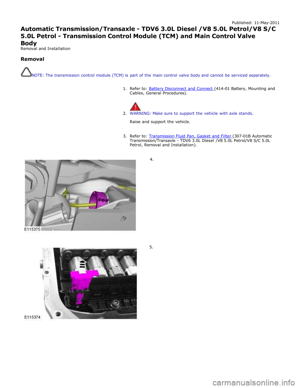
NOTE: The transmission control module (TCM) is part of the main control valve body and cannot be serviced separately.
1. Refer to: Battery Disconnect and Connect (414-01 Battery, Mounting and Cables, General Procedures).
2. WARNING: Make sure to support the vehicle with axle stands.
Raise and support the vehicle.
3. Refer to: Transmission Fluid Pan, Gasket and Filter (307-01B Automatic Transmission/Transaxle - TDV6 3.0L Diesel /V8 5.0L Petrol/V8 S/C 5.0L
Petrol, Removal and Installation).
4.
5.
Page 1556 of 3039
Published: 11-May-2011
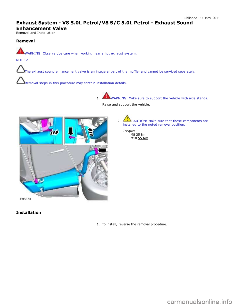
Exhaust System - V8 5.0L Petrol/V8 S/C 5.0L Petrol - Exhaust Sound
Enhancement Valve
Removal and Installation
Removal
WARNING: Observe due care when working near a hot exhaust system.
NOTES:
The exhaust sound enhancement valve is an integeral part of the muffler and cannot be serviced separately.
Removal steps in this procedure may contain installation details.
1. WARNING: Make sure to support the vehicle with axle stands.
Raise and support the vehicle.
Installation
2. CAUTION: Make sure that these components are
installed to the noted removal position.
Torque:
M8 25 Nm M10 55 Nm
1. To install, reverse the removal procedure.
Page 1596 of 3039
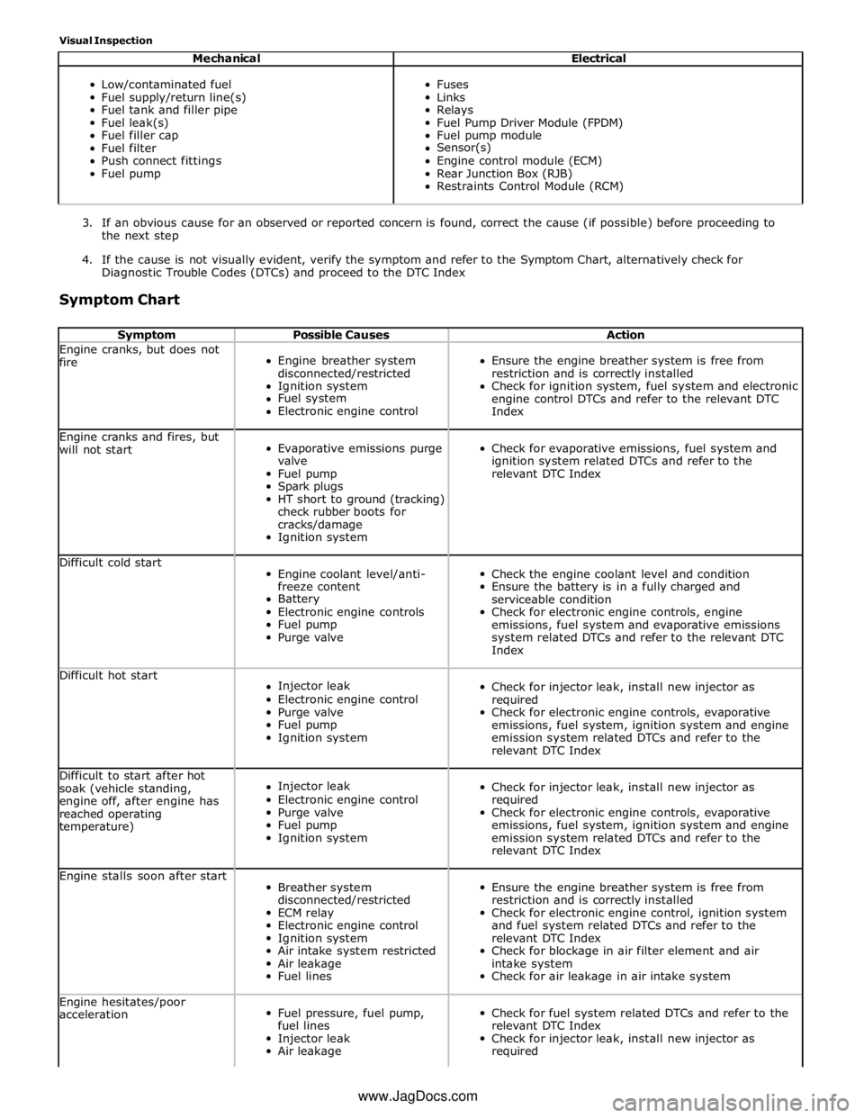
Visual Inspection
Mechanical Electrical
Low/contaminated fuel
Fuel supply/return line(s)
Fuel tank and filler pipe
Fuel leak(s)
Fuel filler cap
Fuel filter
Push connect fittings
Fuel pump
Fuses
Links
Relays
Fuel Pump Driver Module (FPDM)
Fuel pump module
Sensor(s)
Engine control module (ECM)
Rear Junction Box (RJB)
Restraints Control Module (RCM)
3. If an obvious cause for an observed or reported concern is found, correct the cause (if possible) before proceeding to
the next step
4. If the cause is not visually evident, verify the symptom and refer to the Symptom Chart, alternatively check for
Diagnostic Trouble Codes (DTCs) and proceed to the DTC Index
Symptom Chart
Symptom Possible Causes Action Engine cranks, but does not
fire
Engine breather system
disconnected/restricted
Ignition system
Fuel system
Electronic engine control
Ensure the engine breather system is free from
restriction and is correctly installed
Check for ignition system, fuel system and electronic
engine control DTCs and refer to the relevant DTC
Index Engine cranks and fires, but
will not start
Evaporative emissions purge
valve
Fuel pump
Spark plugs
HT short to ground (tracking)
check rubber boots for
cracks/damage
Ignition system
Check for evaporative emissions, fuel system and
ignition system related DTCs and refer to the
relevant DTC Index Difficult cold start
Engine coolant level/anti-
freeze content
Battery
Electronic engine controls
Fuel pump
Purge valve
Check the engine coolant level and condition
Ensure the battery is in a fully charged and
serviceable condition
Check for electronic engine controls, engine
emissions, fuel system and evaporative emissions
system related DTCs and refer to the relevant DTC
Index Difficult hot start
Injector leak
Electronic engine control
Purge valve
Fuel pump
Ignition system
Check for injector leak, install new injector as
required
Check for electronic engine controls, evaporative
emissions, fuel system, ignition system and engine
emission system related DTCs and refer to the
relevant DTC Index Difficult to start after hot
soak (vehicle standing,
engine off, after engine has
reached operating
temperature)
Injector leak
Electronic engine control
Purge valve
Fuel pump
Ignition system
Check for injector leak, install new injector as
required
Check for electronic engine controls, evaporative
emissions, fuel system, ignition system and engine
emission system related DTCs and refer to the
relevant DTC Index Engine stalls soon after start
Breather system
disconnected/restricted
ECM relay
Electronic engine control
Ignition system
Air intake system restricted
Air leakage
Fuel lines
Ensure the engine breather system is free from
restriction and is correctly installed
Check for electronic engine control, ignition system
and fuel system related DTCs and refer to the
relevant DTC Index
Check for blockage in air filter element and air
intake system
Check for air leakage in air intake system Engine hesitates/poor
acceleration
Fuel pressure, fuel pump,
fuel lines
Injector leak
Air leakage
Check for fuel system related DTCs and refer to the
relevant DTC Index
Check for injector leak, install new injector as
required www.JagDocs.com