2010 JAGUAR XFR service
[x] Cancel search: servicePage 1644 of 3039
1 Set speed adjustment switch 2 Time gap switch (only on vehicles with adaptive speed control fitted) 3 Cancel switch 4 Resume switch The speed control switches are located on the RH (right-hand)side of the steering wheel. The switches are connected via fly
leads to the clock spring. The speed control switches are resistive ladder type switches which vary the resistance of a 5 volt
signal sent to them. The signal is returned along a LIN bus to the instrument cluster. The instrument cluster routes the control signals to the ECM on the medium speed CAN
Speed control is engaged by rotating the speed adjustment switch to the + or - positions. Once engaged the speed can be
varied by the speed adjustment switches. Each press of the speed adjustment switch will increase or decrease the set speed
in steps of 1 mph (2 kph).
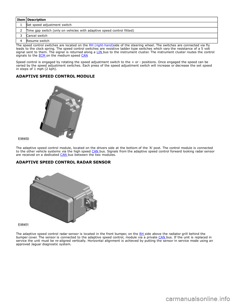
ADAPTIVE SPEED CONTROL MODULE
The adaptive speed control module, located on the drivers side at the bottom of the 'A' post. The control module is connected
to the other vehicle systems via the high speed CAN bus. Signals from the adaptive speed control forward looking radar sensor are received on a dedicated CAN bus between the two modules.
ADAPTIVE SPEED CONTROL RADAR SENSOR
The adaptive speed control radar sensor is located in the front bumper, on the RH side above the radiator grill behind the bumper cover. The sensor is connected to the adaptive speed control, module via a private CAN bus. If the unit is replaced in service the unit must be re-aligned vertically. Horizontal alignment is achieved by putting the sensor in service mode using an
approved Jaguar diagnostic system.
Page 1654 of 3039
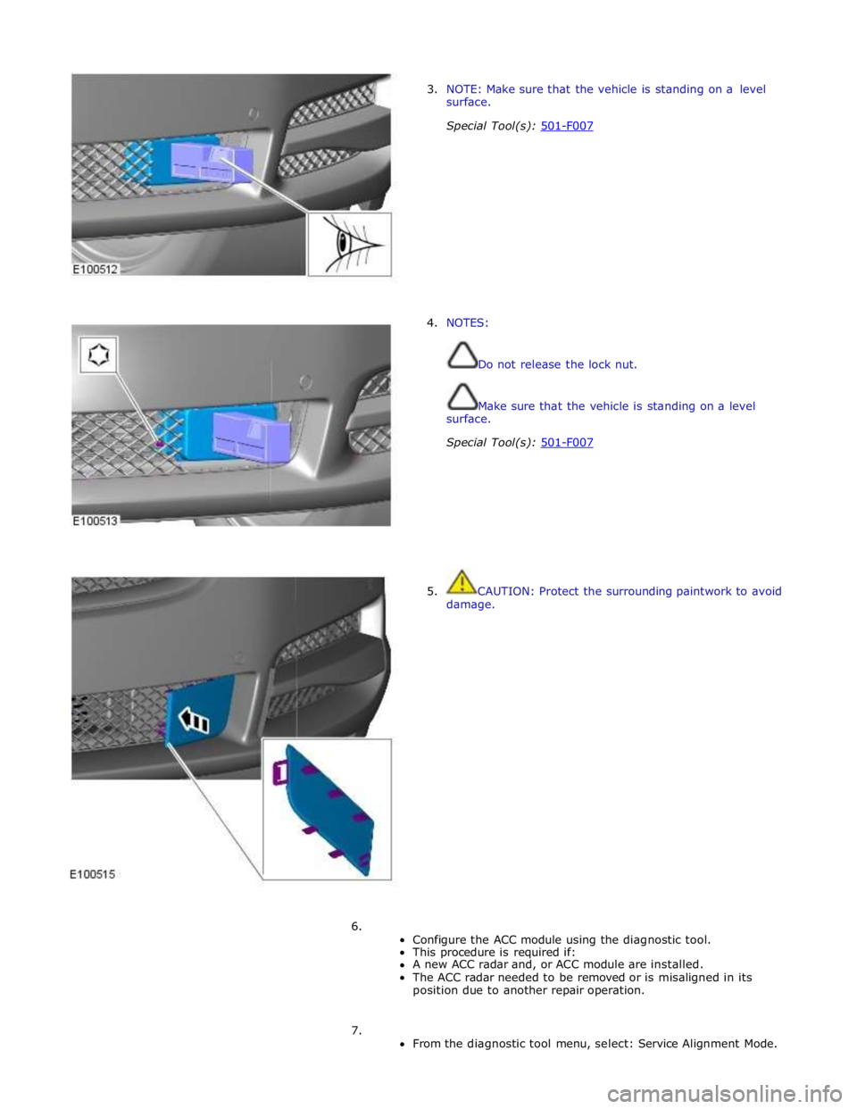
3. NOTE: Make sure that the vehicle is standing on a level
surface.
Special Tool(s): 501-F007
4. NOTES:
Do not release the lock nut.
Make sure that the vehicle is standing on a level
surface.
Special Tool(s): 501-F007
5. CAUTION: Protect the surrounding paintwork to avoid
damage.
6.
Configure the ACC module using the diagnostic tool.
This procedure is required if:
A new ACC radar and, or ACC module are installed.
The ACC radar needed to be removed or is misaligned in its
position due to another repair operation.
7.
From the diagnostic tool menu, select: Service Alignment Mode.
Page 1701 of 3039
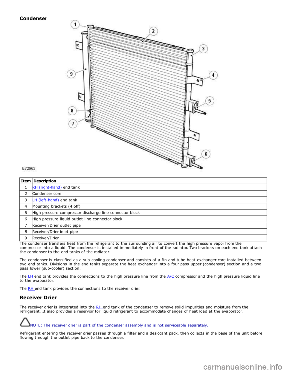
Item Description 1 RH (right-hand) end tank 2 Condenser core 3 LH (left-hand) end tank 4 Mounting brackets (4 off) 5 High pressure compressor discharge line connector block 6 High pressure liquid outlet line connector block 7 Receiver/Drier outlet pipe 8 Receiver/Drier inlet pipe 9 Receiver/Drier The condenser transfers heat from the refrigerant to the surrounding air to convert the high pressure vapor from the
compressor into a liquid. The condenser is installed immediately in front of the radiator. Two brackets on each end tank attach
the condenser to the end tanks of the radiator.
The condenser is classified as a sub-cooling condenser and consists of a fin and tube heat exchanger core installed between
two end tanks. Divisions in the end tanks separate the heat exchanger into a four pass upper (condenser) section and a two
pass lower (sub-cooler) section.
The LH end tank provides the connections to the high pressure line from the A/C compressor and the high pressure liquid line to the evaporator.
The RH end tank provides the connections to the receiver drier.
Receiver Drier
The receiver drier is integrated into the RH end tank of the condenser to remove solid impurities and moisture from the refrigerant. It also provides a reservoir for liquid refrigerant to accommodate changes of heat load at the evaporator.
NOTE: The receiver drier is part of the condenser assembly and is not serviceable separately.
Refrigerant entering the receiver drier passes through a filter and a desiccant pack, then collects in the base of the unit before
flowing through the outlet pipe back to the condenser. Condenser
Page 1798 of 3039

DTC Description Possible Cause Action B100962
Ignition
Authorisation
LS CAN fault
CJB ignition, power and
ground supply circuits - short,
open circuit
Instrument cluster power and
ground supply circuits - short,
open circuit
Incorrect CJB or instrument
cluster installed
Target SID synchronization
error following re-programming
Noise/EMC related error Carry out any pinpoint tests associated with this DTC using
the manufacturer approved diagnostic system. Check CAN
communications between CJB and instrument cluster. Refer
to the electrical circuit diagrams and check CJB ignition,
power and ground supply circuits for short, open circuit and
instrument cluster power and ground supply circuits for short,
open circuit. Check correct CJB and instrument cluster
installed. Perform the Immobilisation application from the
Set-up menu using the manufacturer approved diagnostic
system. Check CAN network for interference/EMC related
issues B100987
Ignition
Authorisation
CJB ignition, power and
ground supply circuits - short,
open circuit
LS CAN fault
Instrument cluster power and
ground supply circuits - short,
open circuit
Low battery voltage <9 volts Carry out any pinpoint tests associated with this DTC using
the manufacturer approved diagnostic system. Refer to the
electrical circuit diagrams and check CJB ignition, power and
ground supply circuits for short, open circuit and instrument
cluster power and ground supply circuits for short, open
circuit. Check CAN communications between CJB and
instrument cluster. Check battery is in serviceable condition
and fully charged B100A62
Fuel Pump
Authorisation
LS CAN fault
RJB power and ground supply
circuits - short, open circuit
Instrument cluster power and
ground supply circuits - short,
open circuit
Incorrect RJB or instrument
cluster installed
Target SID synchronization
error following re-programming
Noise/EMC related error Carry out any pinpoint tests associated with this DTC using
the manufacturer approved diagnostic system. Check CAN
communications between RJB and instrument cluster. Refer
to the electrical circuit diagrams and check RJB power and
ground supply circuits for short, open circuit and instrument
cluster power and ground supply circuits for short, open
circuit. Check correct RJB and instrument cluster installed.
Perform the Immobilisation application from the Set-up menu
using the manufacturer approved diagnostic system. Check
CAN network for interference/EMC related issues B100A64
Fuel Pump
Authorisation
Target SID synchronization
error following re-programming
RJB power and ground supply
circuits - short, open circuit
LS CAN fault Carry out any pinpoint tests associated with this DTC using
the manufacturer approved diagnostic system. Perform the
Immobilisation application from the Set-up menu using the
manufacturer approved diagnostic system. Refer to the
electrical circuit diagrams and check RJB power and ground
supply circuits for short, open circuit. Check CAN
communications between RJB and instrument cluster B100A87
Fuel Pump
Authorisation
RJB power and ground supply
circuits - short, open circuit
LS CAN fault
Instrument cluster power and
ground supply circuits - short,
open circuit
Low battery voltage <9 volts Carry out any pinpoint tests associated with this DTC using
the manufacturer approved diagnostic system. Refer to the
electrical circuit diagrams and check RJB power and ground
supply circuits for short, open circuit and instrument cluster
power and ground supply circuits for short, open circuit.
Check CAN communications between RJB and instrument
cluster. Check battery is in serviceable condition and fully
charged B100B67
Column Lock
Ground
Authorisation
Algorithm based failure-signal
is incorrect after the event
Instrument cluster power and
ground supply circuits - short,
open circuit
LS CAN fault
RJB power and ground supply
circuits - short, open circuit
Vehicle speed present when
attempting to power ESCL
Engine speed present when
attempting to power ESCL
PowerMode status > 4 when
attempting to perform lock
action If a non start issue has not been identified, clear the DTC
and check vehicle starts correctly. If a non start issue has
been identified run the manufacturers approved diagnostic
system Start Authorisation Application. Carry out any
pinpoint tests associated with this DTC using the
manufacturer approved diagnostic system. Refer to the
electrical circuit diagrams and check RJB power and ground
supply circuits for short, open circuit and instrument cluster
power and ground supply circuits for short, open circuit.
Check CAN communications between RJB and instrument
cluster. Check for invalid vehicle speed signal from
ABS/instrument cluster gateway. Check for invalid engine
speed signal from ECM/instrument cluster gateway. Check for
invalid signal from CJB B100B87
Column Lock
Ground
Authorisation
Instrument cluster power and
ground supply circuits - short,
open circuit
LS CAN fault
RJB power and ground supply
circuits - short, open circuit Carry out any pinpoint tests associated with this DTC using
the manufacturer approved diagnostic system. Refer to the
electrical circuit diagrams and check RJB power and ground
supply circuits for short, open circuit and instrument cluster
power and ground supply circuits for short, open circuit.
Check CAN communications between RJB and instrument
cluster
Page 1802 of 3039

DTC Description Possible Cause Action programming state
Attempted to program a non
default key
Instrument cluster Cold init
whilst in Ignition On state,
without key being present in
the SCU
Race condition caused by
closing driver door and
pressing the start button
within a small time window
Passive Key search function
from last door closed and key
inserted in the SCU instrument cluster. Design condition - advise customer of
starting sequence. Design condition - determine customer
transponder key usage B1B0187 Key Transponder
LIN fault
Instrument cluster power and
ground supply circuits - short,
open circuit
Smartcard docking station
power and ground supply
circuits - short, open circuit Carry out any pinpoint tests associated with this DTC using
the manufacturer approved diagnostic system. Check LIN
communications between smartcard docking station and
instrument cluster. Refer to the electrical circuit diagrams
and check smartcard docking station power and ground
supply circuits for short, open circuit and instrument cluster
power and ground supply circuits for short, open circuit B1B3305
Target I.D.
Transfer
CAN fault
ECM ignition, power and
ground supply circuits - short,
open circuit
Instrument cluster power and
ground supply circuits - short,
open circuit
ECM or instrument cluster
incorrectly configured Carry out any pinpoint tests associated with this DTC using
the manufacturer approved diagnostic system. Check CAN
communications between ECM and instrument cluster. Refer
to electrical circuit diagrams and check ECM ignition, power
and ground supply circuits for short, open circuit and
instrument cluster power and ground supply circuits for short,
open circuit. Perform the Immobilisation application from the
Set-up menu using the manufacturer approved diagnostic
system B1B3362
Target I.D.
Transfer
CAN fault
ECM ignition, power and
ground supply circuits - short,
open circuit
Instrument cluster power and
ground supply circuits - short,
open circuit
Incorrect ECM or instrument
cluster installed
Synchronisation error following
re-programming
Noise/EMC related error Carry out any pinpoint tests associated with this DTC using
the manufacturer approved diagnostic system. Check CAN
communications between ECM and instrument cluster. Refer
to electrical circuit diagrams and check ECM ignition, power
and ground supply circuits for short, open circuit and
instrument cluster power and ground supply circuits for short,
open circuit. Check correct ECM and instrument cluster
installed. Perform the Immobilisation application from the
Set-up menu using the manufacturer approved diagnostic
system. Check CAN network for interference/EMC related
issues B1B3364
Target
identification
transfer
Algorithm based failure -
signal plausibility failure
CAN fault
ECM ignition, power and
ground supply circuits - short,
open circuit
Instrument cluster power and
ground supply circuits - short,
open circuit
electronic steering column lock
status incomplete
Race condition caused by
closing driver door and
pressing the start button
within a small time window If the customer has not reported a non start issue, clear the
DTC and check vehicle starts correctly. If a non start has
been reported run the manufacturers approved diagnostic
system Start Authorisation Application and follow the actions
required for this DTC. Carry out any pinpoint tests associated
with this DTC using the manufacturer approved diagnostic
system. Check CAN communications between ECM and
instrument cluster. Refer to electrical circuit diagrams and
check ECM ignition, power and ground supply circuits for
short, open circuit and instrument cluster power and ground
supply circuits for short, open circuit. Check electronic
steering column lock operation. Advise customer of starting
sequence and to allow time to elapse between closing door
and pressing start button. B1B3387
Target I.D.
Transfer
CAN fault
ECM ignition, power and
ground supply circuits - short,
open circuit
Instrument cluster power and
ground supply circuits - short,
open circuit
Low battery voltage Carry out any pinpoint tests associated with this DTC using
the manufacturer approved diagnostic system. Check CAN
communications between ECM and instrument cluster. Refer
to electrical circuit diagrams and check ECM ignition, power
and ground supply circuits for short, open circuit and
instrument cluster power and ground supply circuits for short,
open circuit. Check battery is in serviceable condition and is
fully charged, check terminals etc www.JagDocs.com
Page 1821 of 3039
Published: 11-May-2011
Information and Message Center - Information and Message Center - System
Operation and Component Description
Description and Operation
System Operation
SERVICE INTERVAL INDICATOR - 3.0L V6 DIESEL, 5.0L V8 SUPERCHARGER AND 5.0L V8 NATURALLY ASPIRATED ENGINES ONLY
If the vehicle is within 3,200 kilometers (1,988 miles) of a service, the message center will display 'SERVICE REQUIRED IN
XXXX km or MILES'. The display reduces the 'service required in' readout by increments every 50 kilometers (30 miles). If this
distance drops below 1 km (0.6 miles), the message center will display 'SERVICE REQUIRED'.
These messages are displayed every time the vehicle enters power mode 6, for 4 seconds after the instrument cluster bulb
check routine has finished.
NOTE: The message center will display distance to next service in miles on an instrument cluster fitted with a Miles Per
Hour (MPH) speedometer unless the driver has changed the display units on the Touch Screen Display (TSD).
Reset Procedure
To re-set the service interval indicator, the following process switch presses must each be carried out within 3 seconds:
With the vehicle in power mode 0, (ignition off) press and hold the rear fog lamp switch
Allow the vehicle to enter power mode 6 (Press the start button without a foot on the brake)
Immediately release the rear fog lamp switch
Press and hold the trip computer cycle switch
Press and hold the rear fog lamp switch
Continue to hold the trip computer and rear fog lamp switches
If the process has been successful, the message center will display 'RESETTING SERVICE MODE' and then display
'SERVICE MODE RESET' after 10 seconds
Release both switches and return the vehicle ignition to off, power mode 0.
MESSAGE CENTER Component Description
The message center LCD (liquid crystal display) display has a viewable area of 126 pixels horizontal and 174 pixels vertical. It
is divided into six information display zones as follows, starting from the top:
Set speed
Transmission position
Warning /message display
JaguarDrive Optimization icon
Odometer/Trip computer information
Fuel level.
The message center is active at all times when the ignition is on and can also be active when the ignition is off, dependant on
the information to be displayed. The message center LCD illumination is controlled by the sun load light sensor located on the instrument panel. In bright conditions, the illumination is set to maximum brightness. As the ambient light levels drop, the
illumination dims. When the lights are switched on or activated by the 'AUTO' function, the illumination operates in the same
way until a defined ambient light threshold is reached, at this point the setting of the panel illumination dimmer in the
auxiliary light switch will control the brightness.
If more than one message is active, each message is displayed for 4 seconds in the order of priority. Once all messages have
been displayed, they are again displayed in turn for 2 seconds each. Warning messages can be displayed when the ignition is
in accessory power mode 4 which is the initial ignition state when a door is opened.
Message Priority
Messages are assigned priorities which are defined by the effect on driving safety and functional ability of the vehicle. When
new messages are displayed they may be accompanied by a chime from the instrument cluster sounder. A new message will be
displayed immediately, providing the currently displayed message (if there is one) has been displayed for at least 4 seconds. A
warning indicator will be activated simultaneously with the message being displayed. If more than one fault warning message
is being displayed, the messages will cycle, in priority order, with each message being displayed for 2 seconds.
INFORMATION DISPLAY
The transmission display is located in the upper section of the LCD. The transmission position information is sent from the TCM (transmission control module) in a high speed CAN (controller area network) message to the instrument cluster. The
transmission has three modes of operation:
Conventional automatic operation (JaguarDrive selector in 'D' position)
Sport automatic operation (JaguarDrive selector in 'S' position)
Manual gear operation - Jaguar Sequential Shift.
Page 1826 of 3039
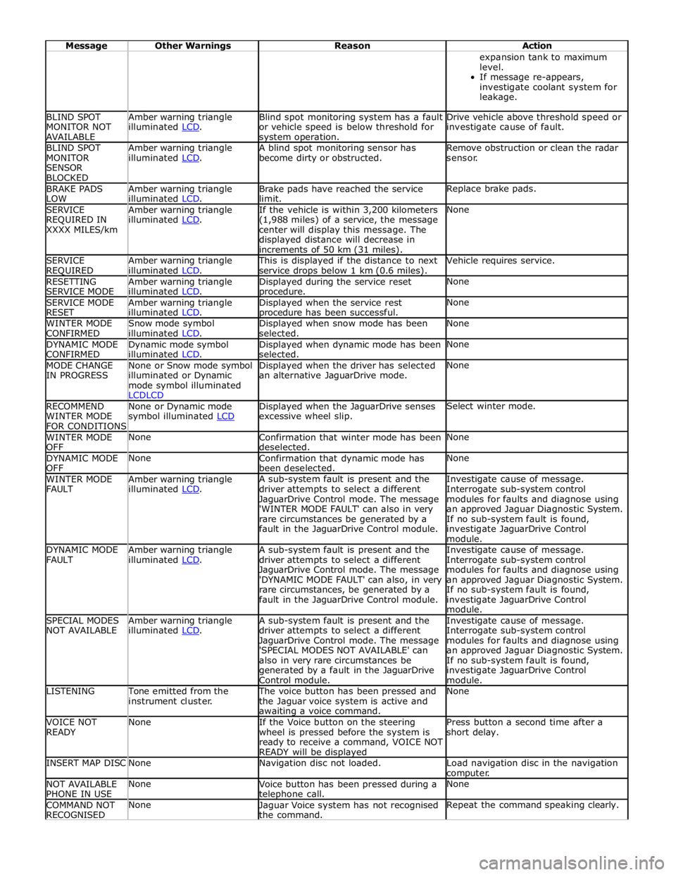
Message Other Warnings Reason Action expansion tank to maximum
level.
If message re-appears,
investigate coolant system for
leakage. BLIND SPOT
MONITOR NOT
AVAILABLE Amber warning triangle
illuminated LCD. Blind spot monitoring system has a fault
or vehicle speed is below threshold for system operation. Drive vehicle above threshold speed or
investigate cause of fault. BLIND SPOT
MONITOR
SENSOR
BLOCKED Amber warning triangle
illuminated LCD. A blind spot monitoring sensor has
become dirty or obstructed. Remove obstruction or clean the radar
sensor. BRAKE PADS
LOW Amber warning triangle
illuminated LCD. Brake pads have reached the service
limit. Replace brake pads. SERVICE
REQUIRED IN
XXXX MILES/km Amber warning triangle
illuminated LCD. If the vehicle is within 3,200 kilometers
(1,988 miles) of a service, the message
center will display this message. The
displayed distance will decrease in
increments of 50 km (31 miles). None SERVICE
REQUIRED Amber warning triangle
illuminated LCD. This is displayed if the distance to next
service drops below 1 km (0.6 miles). Vehicle requires service. RESETTING
SERVICE MODE Amber warning triangle
illuminated LCD. Displayed during the service reset procedure. None SERVICE MODE
RESET Amber warning triangle
illuminated LCD. Displayed when the service rest procedure has been successful. None WINTER MODE
CONFIRMED Snow mode symbol
illuminated LCD. Displayed when snow mode has been
selected. None DYNAMIC MODE
CONFIRMED Dynamic mode symbol
illuminated LCD. Displayed when dynamic mode has been
selected. None MODE CHANGE
IN PROGRESS None or Snow mode symbol
illuminated or Dynamic
mode symbol illuminated
LCDLCD Displayed when the driver has selected
an alternative JaguarDrive mode. None RECOMMEND
WINTER MODE
FOR CONDITIONS None or Dynamic mode
symbol illuminated LCD Displayed when the JaguarDrive senses
excessive wheel slip. Select winter mode. WINTER MODE
OFF None
Confirmation that winter mode has been
deselected. None DYNAMIC MODE
OFF None
Confirmation that dynamic mode has
been deselected. None WINTER MODE
FAULT Amber warning triangle
illuminated LCD. A sub-system fault is present and the
driver attempts to select a different
JaguarDrive Control mode. The message
'WINTER MODE FAULT' can also in very
rare circumstances be generated by a
fault in the JaguarDrive Control module. Investigate cause of message.
Interrogate sub-system control
modules for faults and diagnose using
an approved Jaguar Diagnostic System.
If no sub-system fault is found,
investigate JaguarDrive Control
module. DYNAMIC MODE
FAULT Amber warning triangle
illuminated LCD. A sub-system fault is present and the
driver attempts to select a different
JaguarDrive Control mode. The message
'DYNAMIC MODE FAULT' can also, in very
rare circumstances, be generated by a
fault in the JaguarDrive Control module. Investigate cause of message.
Interrogate sub-system control
modules for faults and diagnose using
an approved Jaguar Diagnostic System.
If no sub-system fault is found,
investigate JaguarDrive Control
module. SPECIAL MODES
NOT AVAILABLE Amber warning triangle
illuminated LCD. A sub-system fault is present and the
driver attempts to select a different
JaguarDrive Control mode. The message
'SPECIAL MODES NOT AVAILABLE' can
also in very rare circumstances be
generated by a fault in the JaguarDrive
Control module. Investigate cause of message.
Interrogate sub-system control
modules for faults and diagnose using
an approved Jaguar Diagnostic System.
If no sub-system fault is found,
investigate JaguarDrive Control
module. LISTENING Tone emitted from the
instrument cluster. The voice button has been pressed and
the Jaguar voice system is active and awaiting a voice command. None VOICE NOT
READY None
If the Voice button on the steering
wheel is pressed before the system is
ready to receive a command, VOICE NOT
READY will be displayed Press button a second time after a
short delay. INSERT MAP DISC None Navigation disc not loaded.
Load navigation disc in the navigation
computer. NOT AVAILABLE
PHONE IN USE None
Voice button has been pressed during a telephone call. None COMMAND NOT
RECOGNISED None
Jaguar Voice system has not recognised
the command. Repeat the command speaking clearly.
Page 1866 of 3039
Published: 07-Aug-2014
Battery and Charging System - General Information - Battery Care
Requirements
Description and Operation
1. INTRODUCTION
This document defines the requirements for care and maintenance of batteries, and the standard of battery care at dealers and
retailers for new vehicles.
This applies to all types of 12 Volt Lead Acid Batteries used in Jaguar and Land Rover vehicles whether they are conventional
flooded technology or Absorbed Glass Mat (AGM – also known as Valve Regulated Lead Acid (VRLA)) technology and also
applies to both Primary, Secondary and Auxiliary Batteries. AGM batteries offer improved resistance to cycling as seen in stop
start applications.
In order to prevent damage to the battery and ensure a satisfactory service life, all processes detailed within this document
must be rigorously adhered to.
It is equally important therefore to note the following key points:
All new vehicles leave the factory with either a transit relay installed and/or have a transit mode programmed into the
vehicle control modules. The transit relay must be removed and the transit mode disabled (where applicable) using an
approved diagnostic system, NOT MORE THAN 72 HOURS before the customer takes delivery.
The battery can be discharged by the following mechanisms:
- Self Discharge: - A lead acid battery will very slowly discharge itself due to its own internal chemical processes
whether it is connected to a vehicle or not.
- Quiescent Discharge: - The vehicle electrical systems when connected to the battery will draw charge from the
battery.
12 Volt Lead Acid Batteries rely on internal chemical processes to create a voltage and deliver current. These processes and
the internal chemical structure of the battery can be damaged if the battery is allowed to discharge over a number of weeks /
months, or is left in a discharged state for a lengthy time period.
On vehicles with conventional ignition keys, these must not be left in the ignition lock barrel when the transit relay
has been removed, otherwise quiescent current will increase and the battery will discharge more rapidly.
For keyless vehicles, the Smart Key must be stored at least 5m (16 ft) away from the vehicle when the vehicle is
parked or stored.
AGM Batteries are fully sealed and cannot have the electrolyte level topped up.
NOTE: Dealers and retailers involved in the storage / handling of vehicles and replacement batteries have a responsibility
to ensure that only a fully charged battery may be processed through the distribution selling chain.
2. GENERAL RULES FOR BATTERY CARE
2.1 Dealer Demonstration Vehicles
Vehicles used as dealer demonstrator(s), in a showroom, must be connected to a JLR approved showroom conditioner capable
of delivering 50 Amps. This will prevent the battery from being damaged.
2.2 Software Reflash, SDD work or Ignition On related workshop activities
Due to the high electrical current demand and high depth of discharge that can occur during vehicle software re-flash activities,
SDD work or ignition on (power mode 6) related work in the workshop, vehicles that are undergoing such activities MUST have a
JLR approved power supply capable of delivering 50 Amps or more.
2.3 Extended Vehicle Rework
For any extended vehicle rework that results in consuming vehicle power, either the battery should be disconnected or a JLR
approved power supply connected.
2.4 Jump Starting New vehicles before they have been delivered to the customer
It is the dealer / retailers responsibility to make sure the battery is not allowed to discharge by following the
instructions and processes defined in this manual.
However, if circumstances dictate that a new vehicle must be jump started due to a discharged battery whilst the
vehicle is in the dealer / retailers care, the battery on this vehicle must be replaced with a new one prior to delivery
to the customer at the dealer / retailers liability.
The vehicle should also undergo investigation as to why the battery became discharged.
Do not connect the jump starting cable to the negative (-) terminal of the battery. Always connect to the recommended
earth point. As defined in the owners handbook or service documentation for that vehicle. 2.5 AGM Batteries
AGM batteries must not be charged above 14.8 Volts. Doing so will damage them.
AGM Batteries must be tested with a capable battery tester as detailed in the Equipment section (Section 5) of this