2010 JAGUAR XFR service
[x] Cancel search: servicePage 1936 of 3039
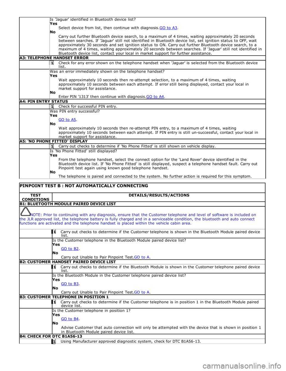
Is 'Jaguar' identified in Bluetooth device list? Yes
Select device from list, then continue with diagnosis.GO to A3. No
Carry out further Bluetooth device search, to a maximum of 4 times, waiting approximately 20 seconds
between searches. If 'Jaguar' still not identified in Bluetooth device list, set ignition status to OFF, wait
approximately 30 seconds and set ignition status to ON. Carry out further Bluetooth device search, to a
maximum of 4 times, waiting approximately 20 seconds between searches. If 'Jaguar' still not identified in
Bluetooth device list, contact your local in market support for further assistance. A3: TELEPHONE HANDSET ERROR 1 Check for any error shown on the telephone handset when 'Jaguar' is selected from the Bluetooth device list. Was an error immediately shown on the telephone handset? Yes
Wait approximately 10 seconds then re-attempt selection, to a maximum of 4 times, waiting
approximately 10 seconds between each attempt. If error still being displayed, contact your local in
market support for assistance.
No
Enter PIN '1313' then continue with diagnosis.GO to A4. A4: PIN ENTRY STATUS 1 Check for successful PIN entry. Was PIN entry successful? Yes
GO to A5. No
Wait approximately 10 seconds then re-attempt PIN entry, to a maximum of 4 times, waiting
approximately 10 seconds between each attempt. If PIN entry is still un-successful, contact your local in
market support for assistance. A5: 'NO PHONE FITTED' DISPLAY 1 Carry out checks to determine if 'No Phone Fitted' is still shown on vehicle display. Is 'No Phone Fitted' still displayed? Yes
From the telephone handset, select the connect option for the 'Land Rover' device identified in the
Bluetooth device list. If 'No Phone Fitted' is still displayed, suspect a telephone handset fault. Carry out
Pinpoint test again using known good telephone handset.
No
The telephone is paired and connected to the system. No further action is required for this symptom.
PINPOINT TEST B : NOT AUTOMATICALLY CONNECTING TEST
CONDITIONS DETAILS/RESULTS/ACTIONS B1: BLUETOOTH MODULE PAIRED DEVICE LIST
NOTE: Prior to continuing with any diagnosis, ensure that the Customer telephone and level of software is included on
the JLR approved list, the telephone battery is fully charged and in a serviceable condition, the bluetooth and auto connect
functions are activated and the telephone handset is placed within the vehicle cabin area. 1 Carry out checks to determine if the Customer telephone is shown in the Bluetooth Module paired device list. Is the Customer telephone in the Bluetooth Module paired device list?
Yes
GO to B2. No
Carry out Unable to Pair Pinpoint Test.GO to A. B2: CUSTOMER HANDSET PAIRED DEVICE LIST 1 Carry out checks to determine if the Bluetooth Module is shown in the Customer telephone paired device list. Is the Bluetooth Module in the Customer telephone paired device list?
Yes
GO to B3. No
Carry out Unable to Pair Pinpoint Test.GO to A. B3: CUSTOMER TELEPHONE IN POSITION 1 1 Carry out checks to determine if the Customer telephone is in position 1 in the Bluetooth Module paired device list. Is the Customer telephone in position 1?
Yes
GO to B4. No
Advise Customer that auto connection will only be attempted with the device that is shown in position 1
in Bluetooth Module paired device list. B4: CHECK FOR DTC B1A56-13 1 Using Manufacturer approved diagnostic system, check for DTC B1A56-13.
Page 1937 of 3039
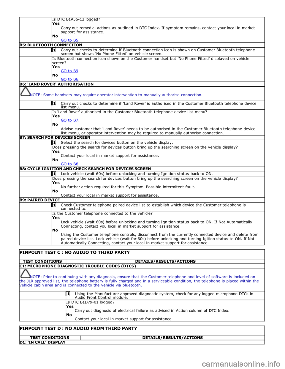
Is DTC B1A56-13 logged?
Yes
Carry out remedial actions as outlined in DTC Index. If symptom remains, contact your local in market
support for assistance.
No
GO to B5. B5: BLUETOOTH CONNECTION 1 Carry out checks to determine if Bluetooth connection icon is shown on Customer Bluetooth telephone screen but shows 'No Phone Fitted' on vehicle screen. Is Bluetooth connection icon shown on the Customer handset but 'No Phone Fitted' displayed on vehicle
screen?
Yes
GO to B9. No
GO to B6. B6: 'LAND ROVER' AUTHORISATION
NOTE: Some handsets may require operator intervention to manually authorise connection. 1 Carry out checks to determine if 'Land Rover' is authorised in the Customer Bluetooth telephone device list menu. Is 'Land Rover' authorised in the Customer Bluetooth telephone device list menu?
Yes
GO to B7. No
Advise customer that 'Land Rover' needs to be authorised in the Customer Bluetooth telephone device
list menu, or operator intervention may be required to manually authorise connection. B7: SEARCH FOR DEVICES SCREEN 1 Select the search for devices button on the vehicle display. Does pressing the search for devices button bring up the searching screen on the vehicle display?
Yes
Contact your local in market support for assistance.
No
GO to B8. B8: CYCLE IGNITION AND CHECK SEARCH FOR DEVICES SCREEN 1 Lock vehicle (wait 60s) before unlocking and turning Ignition status back to ON. Does pressing the search for devices button bring up the searching screen on the vehicle display?
Yes
No further action required for this Symptom. Possible intermitent fault.
No
Contact your local in market support for assistance. B9: PAIRED DEVICE 1 Check Customer telephone paired device list to establish which device the Customer telephone is connected to. Is the Customer telephone connected to the vehicle?
Yes
Lock vehicle (wait 60s) before unlocking and turning Ignition status back to ON. If Not Automatically
Connecting, contact you local in market support for assistance.
No
Using the Customer telephone controls, disconnect from the currently connected device and delete from
paired device list. Lock vehicle (wait for 60s) before unlocking and turning Igition status to ON. If Not Automatically Connecting, contact your local in market support for assistance.
PINPOINT TEST C : NO AUDIO TO THIRD PARTY TEST CONDITIONS DETAILS/RESULTS/ACTIONS C1: MICROPHONE DIAGNOSTIC TROUBLE CODES (DTCS)
NOTE: Prior to continuing with any diagnosis, ensure that the Customer telephone and level of software is included on
the JLR approved list, the telephone battery is fully charged and in a serviceable condition, the telephone is placed within the
vehicle cabin area and is connected to the vehicle via bluetooth. 1 Using the Manufacturer approved diagnostic system, check for any logged microphone DTCs in Audio Front Control module. Is DTC B1D79-01 logged? Yes
Carry out diagnosis of electrical failure as advised in Action column of DTC Index.
No
Contact your local in market support for assistance.
PINPOINT TEST D : NO AUDIO FROM THIRD PARTY TEST CONDITIONS DETAILS/RESULTS/ACTIONS D1: 'IN CALL' DISPLAY
Page 1938 of 3039
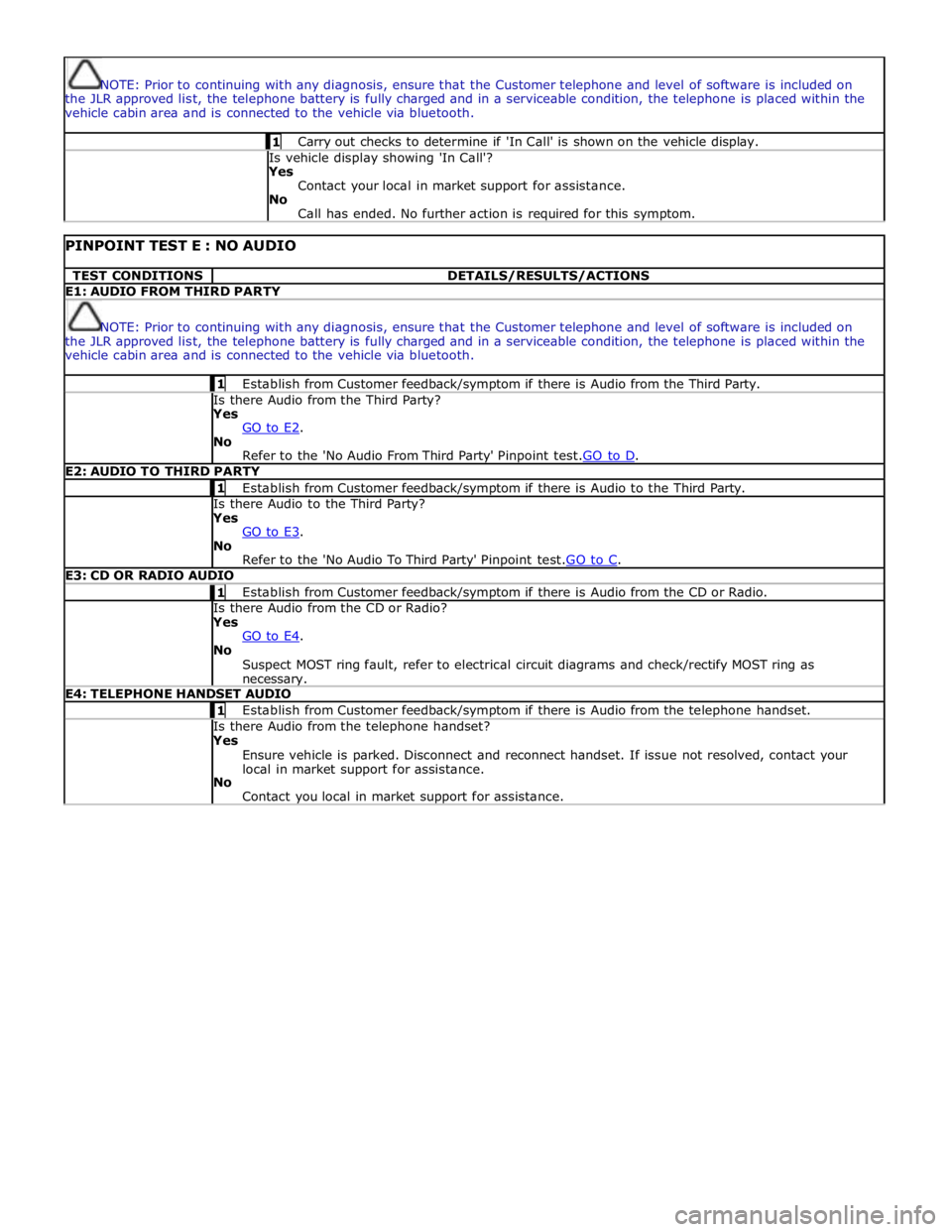
NOTE: Prior to continuing with any diagnosis, ensure that the Customer telephone and level of software is included on
the JLR approved list, the telephone battery is fully charged and in a serviceable condition, the telephone is placed within the
vehicle cabin area and is connected to the vehicle via bluetooth. 1 Carry out checks to determine if 'In Call' is shown on the vehicle display. Is vehicle display showing 'In Call'?
Yes
Contact your local in market support for assistance.
No
Call has ended. No further action is required for this symptom.
PINPOINT TEST E : NO AUDIO TEST CONDITIONS DETAILS/RESULTS/ACTIONS E1: AUDIO FROM THIRD PARTY
NOTE: Prior to continuing with any diagnosis, ensure that the Customer telephone and level of software is included on
the JLR approved list, the telephone battery is fully charged and in a serviceable condition, the telephone is placed within the
vehicle cabin area and is connected to the vehicle via bluetooth. 1 Establish from Customer feedback/symptom if there is Audio from the Third Party. Is there Audio from the Third Party? Yes
GO to E2. No
Refer to the 'No Audio From Third Party' Pinpoint test.GO to D. E2: AUDIO TO THIRD PARTY 1 Establish from Customer feedback/symptom if there is Audio to the Third Party. Is there Audio to the Third Party? Yes
GO to E3. No
Refer to the 'No Audio To Third Party' Pinpoint test.GO to C. E3: CD OR RADIO AUDIO 1 Establish from Customer feedback/symptom if there is Audio from the CD or Radio. Is there Audio from the CD or Radio? Yes
GO to E4. No
Suspect MOST ring fault, refer to electrical circuit diagrams and check/rectify MOST ring as necessary. E4: TELEPHONE HANDSET AUDIO 1 Establish from Customer feedback/symptom if there is Audio from the telephone handset. Is there Audio from the telephone handset? Yes
Ensure vehicle is parked. Disconnect and reconnect handset. If issue not resolved, contact your
local in market support for assistance.
No
Contact you local in market support for assistance.
Page 1945 of 3039
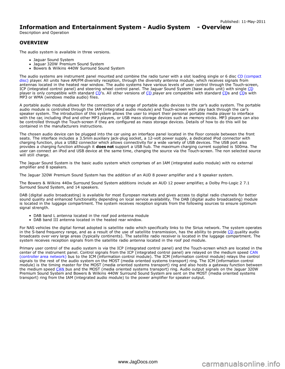
player is only compatible with standard CD's. All other versions of CD player are compatible with standard CDs and CDs with MP3 or WMA (windows media audio) files.
A portable audio module allows for the connection of a range of portable audio devices to the car’s audio system. The portable
audio module is controlled through the IAM (integrated audio module) and Touch-screen with play back through the car’s
speaker system. The introduction of this system allows the user to import their personal portable media player to interface
with the car, including iPod and other MP3 players, or USB mass storage devices such as memory sticks. MP3 players can also
be controlled through the Touch-screen if they are configured as mass storage devices. Details of how to do this will be
contained in the manufacturers instructions.
The chosen audio device can be plugged into the car using an interface panel located in the floor console between the front
seats. The interface includes a 3.5mm auxiliary jack-plug socket, a 12-volt power supply, a dedicated iPod connector with
charging function, plus a USB2 connector which allows connectivity for a wide variety of USB devices. The USB port also
provides a charging function although it does not support a USB hub. The maximum charging current supplied is 500ma. The
user can connect an iPod and USB device at the same time, changing the source via the Touch-screen. The non selected source
will still charge.
The Jaguar Sound System is the basic audio system which comprises of an IAM (integrated audio module) with no external
amplifier and 8 speakers.
The Jaguar 320W Premium Sound System has the addition of an AUD 8 power amplifier and a 9 speaker system.
The Bowers & Wilkins 440w Surround Sound System additions include an AUD 12 power amplifier, a Dolby Pro-Logic 2 7.1
Surround Sound System, and 14 speakers.
DAB (digital audio broadcasting) is available for most European markets and gives access to digital radio channels for better
sound quality and enhanced functionality depending on local service availability. The DAB (digital audio broadcasting) module
is located in the luggage compartment. The system receives reception signals from the following sources to ensure optimum
signal strength.
DAB band L antenna located in the roof pod antenna module
DAB band III antenna located in the heated rear window.
For NAS vehicles the digital format adopted is satellite radio which specifically links to the Sirius network. The system operates
in the S-band frequency range, and as a result of the use of satellite transmission, has the ability to provide CD quality audio broadcasts over very large areas (typically continents). The satellite radio receiver is located in the luggage compartment. The
system receives reception signals from the satellite radio antenna located in the roof pod module.
Primary user control of the audio system is via the ICP (integrated control panel) and the Touch-screen which are located in the
center of the instrument panel. Control signals from the ICP (integrated control panel) are relayed on the medium speed CAN
(controller area network) bus to the ICM (information control module). The ICM (information control module) relays the control
signals to the rest of the audio system on the MOST (media oriented systems transport) ring. The ICM (information control
module) is the timing master for the MOST (media oriented systems transport) ring and also hosts a gateway function between
the medium speed CAN bus and the MOST (media oriented systems transport) ring. Audio output signals on the Jaguar 320W Premium Sound System and Bowers & Wilkins 440W Surround Sound System are sent on the MOST (media oriented systems
transport) ring from the IAM (integrated audio module) to the power amplifier for speaker output. www.JagDocs.com
Page 1956 of 3039

controlled through the device itself.
NOTE: The system will support devices with a storage capacity up to 256 GB which is approximately 65,000 audio tracks.
The wiring link harness between the portable audio module and interface panel consists of hardwired and digital connections
for data and signal exchange. The MOST carries the communication signals and information between the portable audio module
to the IAM and touch-screen. Audio output to the speaker system is controlled by the IAM or power amplifier depending on the
audio system specification.
POWER AMPLIFIER
The audio system has three amplification options dependant on the audio system specification:
IAM internal amplifier
Alpine AUD 8
Alpine AUD 12
The power amplifier is located in the left hand side of the luggage compartment and is connected to the audio system via the
MOST bus. Speaker connections are hardwired.
If the power amplifier is replaced it must be configured as a new module using the Jaguar diagnostic equipment.
Calibration of the power amplifier using the Jaguar approved diagnostic equipment enables updates to be downloaded as new
technology becomes available or any fault concerns require software updates.
DIGITAL AUDIO BROADCASTING
DAB is a digital radio network designed to provide reliable, multi-service broadcasting for reception by mobile, portable and
fixed receivers.
DAB provides a clear signal with minimal interference, hiss or fading. After a channel (or station) has been tuned and stored, it
does not need retuning.
NOTE: Radio signals travel in a straight line so large obstacles, such as tall buildings, can shield the vehicle from the
signal causing temporary loss of reception (known as dead spots).
Digital radio is transmitted from regional terrestrial transmitters. Some local digital radio channels are not available outside
the range of a transmitter. To receive new local channels during vehicle movement around a country, the auto-tune function is
used to build new channel lists.
Page 1957 of 3039
NOTE: When the vehicle DAB radio is first used the system will not receive any digital stations until the auto-tune
function has been completed.
Digital radio channels are organized into groups called ensembles (also known as multiplexes). Some individual channels may
also provide a number of subchannels. For example, if several sports events are being held simultaneously, the channel may
temporarily choose to broadcast each different event on a separate subchannel.
DAB is broadcast across Europe, Canada and parts of Asia. System transmission is via a terrestrial network, on two separate
broadcasting bands:
DAB band-L
DAB band III
The DAB system requires additional components to be added to the audio system. DAB antennas and a receiver are fitted to
allow reception of the service.
Operation of the DAB system is the same as the radio operation with selections made through the touch-screen and ICP to
access and navigate the system functions.
The DAB receiver is a dedicated tuner which is controlled by the ICM on the MOST ring. The receiver processes the signals from
the DAB antennas. Information is transmitted on the MOST ring and processed by the ICM. The processed information is sent
out to the power amplifier or IAM (with internal amplifier) and broadcast through the speaker system.
No configuration procedure is required if the DAB receiver is replaced. Calibration of the DAB receiver using the Jaguar
approved diagnostic equipment enables updates to be downloaded as new technology becomes available or any fault concerns
require software updates.
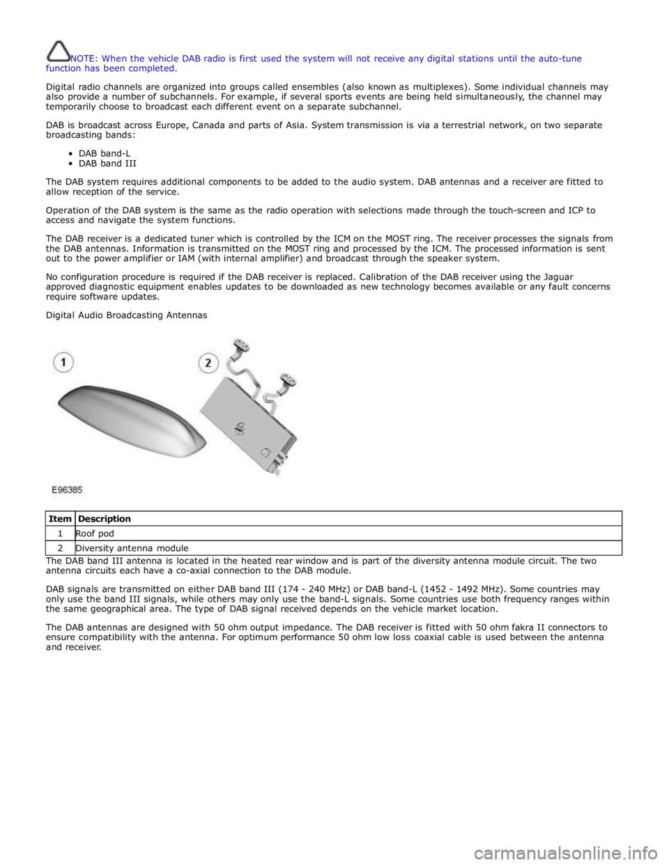
Digital Audio Broadcasting Antennas
Item Description 1 Roof pod 2 Diversity antenna module The DAB band III antenna is located in the heated rear window and is part of the diversity antenna module circuit. The two
antenna circuits each have a co-axial connection to the DAB module.
DAB signals are transmitted on either DAB band III (174 - 240 MHz) or DAB band-L (1452 - 1492 MHz). Some countries may
only use the band III signals, while others may only use the band-L signals. Some countries use both frequency ranges within
the same geographical area. The type of DAB signal received depends on the vehicle market location.
The DAB antennas are designed with 50 ohm output impedance. The DAB receiver is fitted with 50 ohm fakra II connectors to
ensure compatibility with the antenna. For optimum performance 50 ohm low loss coaxial cable is used between the antenna
and receiver.
Page 1958 of 3039
The digital radio format adopted for NAS vehicles is satellite radio. Satellite service providers transmit a signal from their
up-link facility (which is the original point of transmission of data, voice or other information through an antenna system) to a
satellite where the signal is then down linked to both the terrestrial repeater network and the individual satellite car radios.
The radio switches between the satellite signal and the repeater network signal depending on the strength of the signal at any
given time.
The Sirius satellite system comprises:
Satellites
Ground repeaters
Up-link ground stations
Radio receiver systems
The Sirius satellite radio system uses three satellites on an inclined elliptical orbit. This ensures that each satellite spends
approximately 16 hours a day over the continent of the USA, with at least one satellite over the country at any one time.
The satellites beam their signals down to the ground where the signal is picked up by receivers or is transmitted to repeater
stations to cover built up areas where the signal is obscured. The satellite service comprises over 100 channels of digital
entertainment which is provided by subscription requiring a monthly payment.
Operation of the satellite radio system is the same as the radio operations with selections made through the Touch-screen and
ICP to access and navigate the system functions.
The satellite radio receiver is a dedicated tuner which is controlled by the ICM on the MOST ring. The receiver filters the
signals from the satellite radio antenna. Information is transmitted on the MOST ring and processed by the ICM. The processed
information is sent out to the power amplifier or IAM (with internal amplifier) and broadcast through the speaker system.
No configuration procedure is required if the satellite radio receiver is replaced. Calibration of the satellite radio receiver using
the Jaguar approved diagnostic equipment enables updates to be downloaded as new technology becomes available or any
fault concerns require software updates.
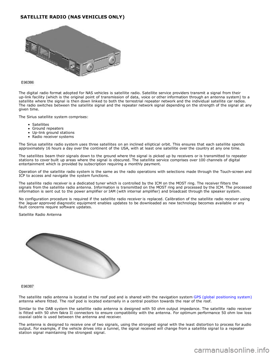
Satellite Radio Antenna
The satellite radio antenna is located in the roof pod and is shared with the navigation system GPS (global positioning system)
antenna where fitted. The roof pod is located externally in a central position towards the rear of the roof.
Similar to the DAB system the satellite radio antenna is designed with 50 ohm output impedance. The satellite radio receiver
is fitted with 50 ohm fakra II connectors to ensure compatibility with the antenna. For optimum performance 50 ohm low loss
coaxial cable is used between the antenna and receiver.
The antenna is designed to receive one of two signals, using the strongest signal with the least distortion to process for audio
output. For example, if the vehicle drives into a tunnel, the signal received will change from a satellite signal to a repeater
station signal maintaining the strongest signal. SATELLITE RADIO (NAS VEHICLES ONLY)
Page 1977 of 3039
In addition to the standard navigation system there are two market dependant systems that supply extra information to the
navigation system and the driver. These are:
TMC (traffic message channel) (Europe only)
VICS (vehicle information and communication system) (Japan only)
The TMC (traffic message channel) is a function of the FM (frequency modulation)RDS (radio data system). The system
broadcasts real-time traffic and weather information. Data messages are received and decoded by the TMC (traffic message
channel) integral receiver and processed by the navigation computer. TMC (traffic message channel) messages can be filtered
by the navigation computer so that only those relevant to the current journey are displayed, allowing the navigation system to
offer dynamic route guidance - alerting the driver of a problem on the planned route and calculating an alternative route to
avoid the incident. All TMC (traffic message channel) events on the map can be viewed not just the ones on the calculated
route.
TMC (traffic message channel) traffic information systems conform to a global standard that has been adopted by traffic data
gatherers, information service providers, broadcasters and vehicle/receiver manufacturers.
All TMC (traffic message channel) receivers use the same list of event codes, while the location database (on the map disc)
contains both a country-specific set of location codes for the strategic European road network.
TMC (traffic message channel) traffic data is currently broadcast in many European countries.
The VICS (vehicle information and communication system) is broadcast in the Japanese market.
The VICS (vehicle information and communication system) supplies information to enable the navigation computer to re-route
the navigation guidance or to inform the vehicle driver of traffic conditions in the vehicles vicinity. Information is provided to
the system through 3 routes:
RF (radio frequency) transmission
Infra-red transmission
FM multiplex transmissions
The RF (radio frequency) transmissions are generally transmitted from road side beacons mainly on expressways. The
information transmitted is as follows:
Traffic congestion
Travel time to next intersection
Traffic conditions in surrounding areas and expressway turn offs
Traffic accidents
Speed limits
Lane regulations
Tire change
Parking availability at expressway service areas and parking areas
Infra-Red transmissions are transmitted from road side beacons on major trunk roads. The information transmitted is:
Traffic congestion and travel time
Traffic accidents
Breakdowns
Road works restrictions
Parking availability
FM transmissions are broadcast as part of the FM multiplex broadcasting system from NHK FM stations. Information transmitted is:
Traffic congestion and travel time for wide areas
Traffic accidents, road works, speed limits and lane restrictions for a wide area
Parking availability information
The traffic data is split from the normal FM transmissions by the diversity antenna module.
Selection of 'Navigation' on the Touch-screen home menu and subsequent sub-menu selection sends a control request signal to
the navigation computer on the MOST (media orientated systems transport) ring. The requested control information is
processed by the navigation computer.
If voice guidance is operational the voice signal information is relayed from the navigation computer on the MOST (media
orientated systems transport) ring to either the IAM (integrated audio unit) or Power Amplifier, dependant on equipment level,
for output on the speaker system. The navigation audio output is through the front speakers whilst the background audio, for
example radio or CD (compact disc), is played at a reduced volume on the rear speakers.
The GPS signal is available to the navigation system at all times when the vehicle ignition is switched on.
Navigation user voice commands are made using the JaguarVoice system. The ICM (information control module) processes the
analogue signal from the JaguarVoice switch into a digital signal. The digital signal is passed from the ICM (information control
module) onto the MOST (media orientated systems transport) system to the JaguarVoice control unit which is integral with the
navigation computer.
The navigation computer sends an instruction via the MOST (media orientated systems transport) ring to the IAM (integrated
audio module) to turn on the microphone facility.
The microphone is hardwired to the IAM (integrated audio module). The spoken voice command signals are relayed from the
IAM (integrated audio module) via the MOST (media orientated systems transport) ring to the navigation computer for