2010 JAGUAR XFR service
[x] Cancel search: servicePage 2684 of 3039
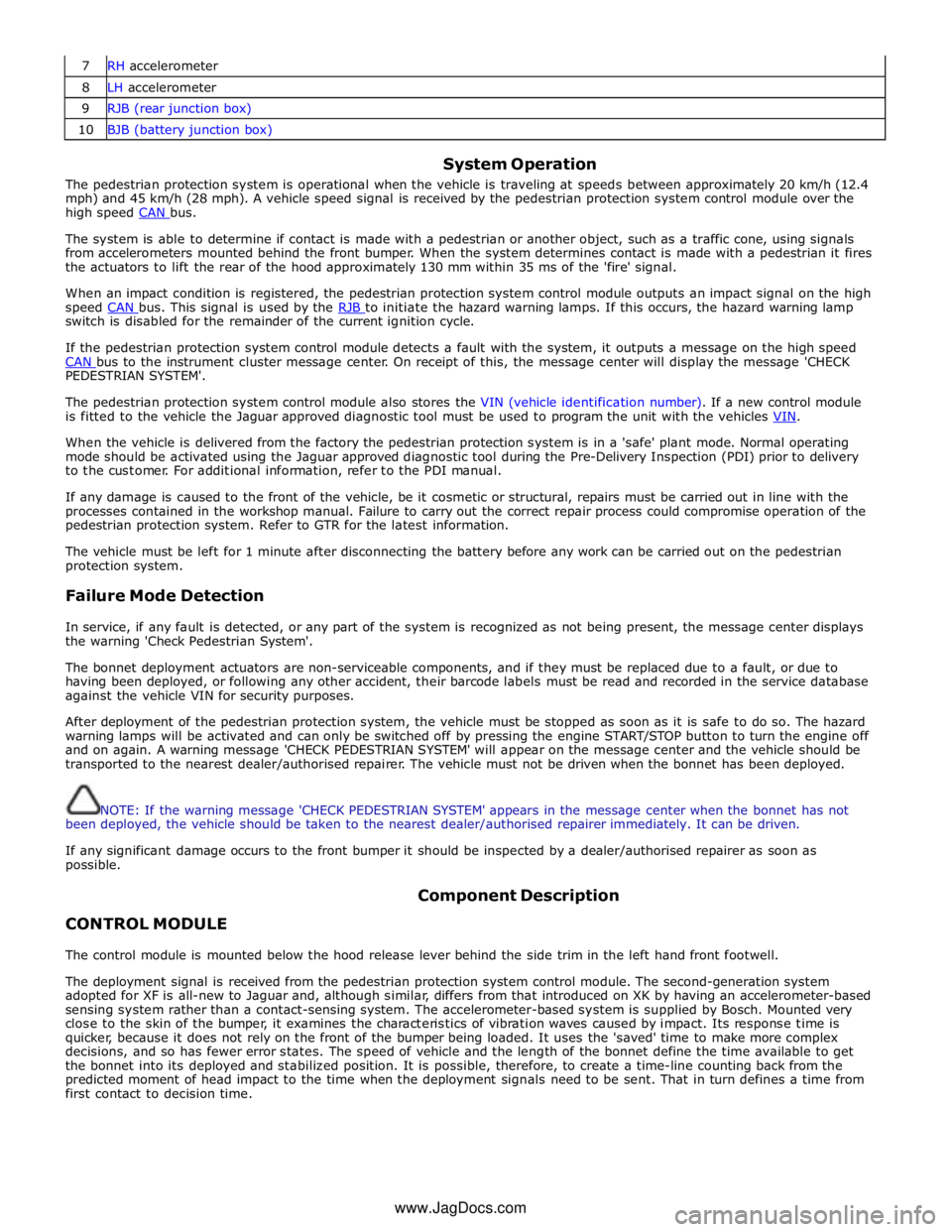
7 RH accelerometer 8 LH accelerometer 9 RJB (rear junction box) 10 BJB (battery junction box)
System Operation
The pedestrian protection system is operational when the vehicle is traveling at speeds between approximately 20 km/h (12.4
mph) and 45 km/h (28 mph). A vehicle speed signal is received by the pedestrian protection system control module over the
high speed CAN bus.
The system is able to determine if contact is made with a pedestrian or another object, such as a traffic cone, using signals
from accelerometers mounted behind the front bumper. When the system determines contact is made with a pedestrian it fires
the actuators to lift the rear of the hood approximately 130 mm within 35 ms of the 'fire' signal.
When an impact condition is registered, the pedestrian protection system control module outputs an impact signal on the high
speed CAN bus. This signal is used by the RJB to initiate the hazard warning lamps. If this occurs, the hazard warning lamp switch is disabled for the remainder of the current ignition cycle.
If the pedestrian protection system control module detects a fault with the system, it outputs a message on the high speed
CAN bus to the instrument cluster message center. On receipt of this, the message center will display the message 'CHECK PEDESTRIAN SYSTEM'.
The pedestrian protection system control module also stores the VIN (vehicle identification number). If a new control module
is fitted to the vehicle the Jaguar approved diagnostic tool must be used to program the unit with the vehicles VIN.
When the vehicle is delivered from the factory the pedestrian protection system is in a 'safe' plant mode. Normal operating
mode should be activated using the Jaguar approved diagnostic tool during the Pre-Delivery Inspection (PDI) prior to delivery
to the customer. For additional information, refer to the PDI manual.
If any damage is caused to the front of the vehicle, be it cosmetic or structural, repairs must be carried out in line with the
processes contained in the workshop manual. Failure to carry out the correct repair process could compromise operation of the
pedestrian protection system. Refer to GTR for the latest information.
The vehicle must be left for 1 minute after disconnecting the battery before any work can be carried out on the pedestrian
protection system.
Failure Mode Detection
In service, if any fault is detected, or any part of the system is recognized as not being present, the message center displays
the warning 'Check Pedestrian System'.
The bonnet deployment actuators are non-serviceable components, and if they must be replaced due to a fault, or due to
having been deployed, or following any other accident, their barcode labels must be read and recorded in the service database
against the vehicle VIN for security purposes.
After deployment of the pedestrian protection system, the vehicle must be stopped as soon as it is safe to do so. The hazard
warning lamps will be activated and can only be switched off by pressing the engine START/STOP button to turn the engine off
and on again. A warning message 'CHECK PEDESTRIAN SYSTEM' will appear on the message center and the vehicle should be
transported to the nearest dealer/authorised repairer. The vehicle must not be driven when the bonnet has been deployed.
NOTE: If the warning message 'CHECK PEDESTRIAN SYSTEM' appears in the message center when the bonnet has not
been deployed, the vehicle should be taken to the nearest dealer/authorised repairer immediately. It can be driven.
If any significant damage occurs to the front bumper it should be inspected by a dealer/authorised repairer as soon as
possible.
CONTROL MODULE Component Description
The control module is mounted below the hood release lever behind the side trim in the left hand front footwell.
The deployment signal is received from the pedestrian protection system control module. The second-generation system
adopted for XF is all-new to Jaguar and, although similar, differs from that introduced on XK by having an accelerometer-based
sensing system rather than a contact-sensing system. The accelerometer-based system is supplied by Bosch. Mounted very
close to the skin of the bumper, it examines the characteristics of vibration waves caused by impact. Its response time is
quicker, because it does not rely on the front of the bumper being loaded. It uses the 'saved' time to make more complex
decisions, and so has fewer error states. The speed of vehicle and the length of the bonnet define the time available to get
the bonnet into its deployed and stabilized position. It is possible, therefore, to create a time-line counting back from the
predicted moment of head impact to the time when the deployment signals need to be sent. That in turn defines a time from
first contact to decision time.
www.JagDocs.com
Page 2723 of 3039

Terotex HV 200 extra spray - 1L can Teroson 176.48 Terotex HV 200 extra spray - 10L tin Teroson 179.40A Terotex HV 200 extra spray - 60L barrel Teroson 170.96J Terotex HV 400 1L can Teroson 169.65Q Terotex HV 400 10L tin Teroson 169.76C Terotex HV 400 60L barrel Teroson 169.85M Teroson cavity spray 500ml aerosol Teroson 155.71A Underbody Wax - - Terotex wax black 1L can Teroson 114.59F Protective wax Teroson 122.73Q Underbody Coating - - Bodyguard stonechip coating (textured) can - black 3M 08868 Bodyguard stonechip coating (textured) can - white 3M 08878 Bodyguard stonechip coating (textured) can - grey 3M 08879 Bodyguard stonechip coating (flat) can - black 3M 08158 Bodyguard stonechip coating (flat) can - grey 3M 08159 Anti chip coating smooth - grey 3M 08886 Terotex record black 1L can Teroson 122.48N Terotex record light 1L can Teroson 165.53S Terotex anti chip compound light (UBC) 1L can Teroson 191.08V Terotex anti chip compound black (UBC) 1L can Teroson 191.32V Trim Adhesive - - Auto adhesive - aerosol - clear (trim) 3M 08080 Auto adhesive - brushable - clear (trim) 3M 08150 Contact adhesive - aerosol - amber 3M 08090 Corrosion Protection - - Zinc spray 3M 09113 Zinc spray Teroson 158.18T Anti Corrosive Agent - - Terotex HV 350 1L can Teroson 141.78L Terotex HV 350 10L can Teroson 160.02T Terotex HV 350 60L barrel Teroson 160.01S Sound Deadening - - Sound deadening sheets 3M 08840 Terodem SP 100 alu Teroson 190.33 Terodem SP 200 Teroson 190.55M Terodem SP 300 50 x 50 Teroson 145.28R Terodem SP 300 100 x 50 Teroson 134.29X Flexible Part Repair - - Flexible part repair material (FPRM) 3M 05900 Adhesives / Thread Locking - - Lock N Seal 243 thread locking Loctite 13701 Lock N Seal 243 thread locking Loctite 14131 Lock N Seal 243 thread locking Loctite 25684 Stud N Bearing fit 271 Loctite 13704 Stud N Bearing fit 271 Loctite 14130 Stud N Bearing fit 271 Loctite 25685 Pipe sealant 577 Loctite 16604 Pipe sealant 577 Loctite 25689 Pipe sealant 55 Loctite 31899 Gasket - - Multi gasket Loctite 25688 Silicone copper Loctite 19245 Silicone copper Loctite 82046 Silicone 596 black Loctite 19242 Silicone 596 black Loctite 59875 3020 gasket adhesive Loctite 31458 NVH Baffle - - Sikabaffle 278 SIKA Approved Service Material Supplier - Contact Details
3M
3M United Kingdom PLC
3M Centre
Cain Road
Bracknell
Berkshire
RG12 8HT
Telephone (01344) 858000
www.3m.com
Page 2726 of 3039
metal surfaces are bolted together always interpose a suitable interface material such as weldable zinc rich primer, extruded
strip, or zinc tape.
Steam Cleaning
Due to the high pressure/temperature generated by steam cleaning equipment, there is a risk that certain adhesives and
corrosion prevention material may become softened or liquified.
Take care not to allow the steam jet to dwell on one area, and keep the nozzle at least 300mm from the panel surface.
CAUTION: Do not remove wax or lacquer from underbody areas during repairs.
Inspection During Maintenance Servicing
It is a requirement of the corrosion warranty that the vehicle is inspected for corrosion by a Jaguar Authorised Repairer during a
routine service, to ensure that the factory-applied protection remains effective.
Rectify any bodywork damage or evidence of corrosion found during inspection as soon as is practicable, both to minimise the
extent of the damage and to ensure the long term effectiveness of the factory-applied corrosion prevention treatment.
Underbody Protection Repairs
Whenever body repairs have been carried out, ensure that full sealing and corrosion protection treatments are reinstated. This
applies both to the damaged areas and also to areas where protection has been indirectly impaired, as a result either of
accident damage or repair operations.
Remove corrosion protection from the damaged areas before straightening or panel beating. This applies in particular to panels
coated with wax, PVC underbody sealer, sound deadening pads etc.
CAUTION: Do not use oxy-acetylene to remove corrosion prevention material. Large volumes of fumes and gases are
liberated by these materials when they burn.
The most common method of removal is by means of a hot air blower with an integral scraper. High temperatures can be
generated with this equipment which may cause fumes. Take care during its use.
Structural Adhesive
CAUTION: When separating a joint with metal to metal adhesive, it is important to avoid distortion. Heat gradually until
the bond weakens sufficiently to permit panel separation - do not apply excessive heat.
NOTE: When spot welding through metal to metal adhesive, take particular care to adjust the equipment setting to
ensure a suitable weld.
Metal to metal adhesive is applied to critical joint areas during factory assembly. The material used is a high temperature,
heat cured, nitrile phenolic which serves to bond two metal surfaces and also to seal the joint against ingress of dust,
moisture and fumes. This material is not suitable for service use and, during repair, should be substituted by an approved
structural adhesive. For panel specific information and to identify the areas of structural adhesive application in repair, refer to
the relevant sheet metal removal and installation procedure.
Expanding Foam Acoustic Seals
Expanding foam acoustic seals are used in various closed-sections of the body to improve vehicle refinement. The seals are
installed during the vehicle body manufacture and expand during the paint process up to ten times original size, thus locking
them into position. They are located such that they prevent noise accentuation along a section and reflect air borne noise
away from the cabin.
The seals have spilt functionality depending on location. The seals located at the base of the body pillars have a primary
function of preventing water ingress when wading. Their secondary function is to prevent noise and dust ingress.
The seal around the fuel filler has a primary function of preventing both fuel and water ingress. With a secondary function of
preventing noise and dust ingress.
The remaining seals primary function is to prevent noise accentuation along a section and reflect air borne noise away from the
cabin.
Another advantage of the seals is that they marginally increase the overall stiffness of the body and its structural performance
in case of a crash.
The seals are manufactured from an expandible polymer.
Replacing Expanding Foam Acoustic Seals
As paint oven temperatures used in a repair workshop are significantly lower than those that are used during manufacture of
the vehicle, (the temperatures are not sufficient to expand the foam), a different process is required to replicate the foam in
repair.
Page 2731 of 3039
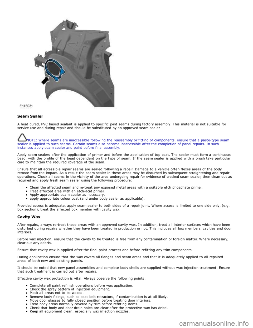
Seam Sealer
A heat cured, PVC based sealant is applied to specific joint seams during factory assembly. This material is not suitable for
service use and during repair and should be substituted by an approved seam sealer.
NOTE: Where seams are inaccessible following the reassembly or fitting of components, ensure that a paste-type seam
sealer is applied to such seams. Certain seams also become inaccessible after the completion of panel repairs. In such
instances apply seam sealer and paint before final assembly.
Apply seam sealers after the application of primer and before the application of top coat. The sealer must form a continuous
bead, with the profile of the bead dependent on the type of seam. If the seam sealer is applied with a brush take particular
care to maintain the required coverage of the seam.
Ensure that all accessible repair seams are sealed following a repair. Damage to a vehicle often flexes areas of the body
remote from the impact. As a result the seam sealer in these areas may be disturbed by subsequent straightening and repair
operations. Check all seams in the vicinity of the area undergoing repair for evidence of cracked seam sealer, then clean out as
required and apply fresh seam sealer using the following procedure:
Clean the affected seam and re-treat any exposed metal areas with a suitable etch phosphate primer.
Treat affected area with an etch-acid primer.
Apply appropriate seam sealer as necessary.
apply appropriate colour coat (and under body sealer as applicable).
Provided access is adequate, apply seam sealer to both sides of a repair joint. Where access is limited to one side only, (e.g.
box section), treat the affected box member with cavity wax.
Cavity Wax
After repairs, always re-treat these areas with an approved cavity wax. In addition, treat all interior surfaces which have been
disturbed during repairs whether they have been treated in production or not. This includes all box members, cavities and door
interiors.
Before wax injection, ensure that the cavity to be treated is free from any contamination or foreign matter. Where necessary,
clear out any debris.
Ensure that cavity wax is applied after the final paint process and before refitting any trim components.
During application ensure that the wax covers all flanges and seam areas and that it is adequately applied to all repaired
areas of both new and existing panels.
It should be noted that new panel assemblies and complete body shells are supplied without wax injection treatment. Ensure
that such treatment is carried out after repairs.
Effective cavity wax protection is vital. Always observe the following points:
Complete all paint refinish operations before wax application.
Check the spray pattern of injection equipment.
Mask all areas not to be waxed.
Remove body fixings, such as seat belt retractors, if contamination is at all likely.
Move door glasses to fully closed position before treating door interiors.
Treat body areas normally covered by trim before refitting items.
Check that body and door drain holes are clear after the protective wax has dried.
Keep all equipment clean, especially wax injection nozzles.
Page 2754 of 3039
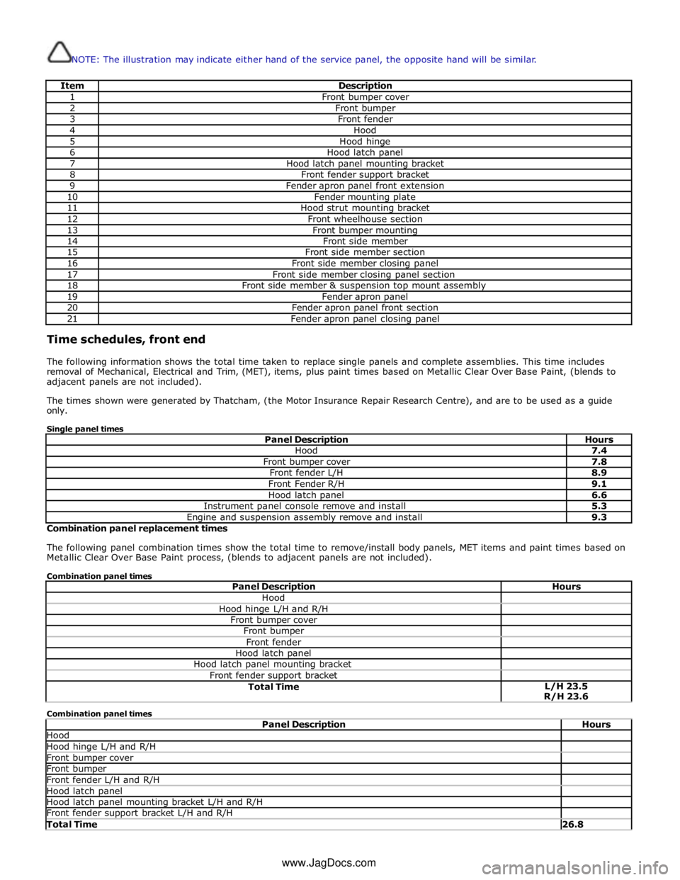
NOTE: The illustration may indicate either hand of the service panel, the opposite hand will be similar.
Item Description 1 Front bumper cover 2 Front bumper 3 Front fender 4 Hood 5 Hood hinge 6 Hood latch panel 7 Hood latch panel mounting bracket 8 Front fender support bracket 9 Fender apron panel front extension 10 Fender mounting plate 11 Hood strut mounting bracket 12 Front wheelhouse section 13 Front bumper mounting 14 Front side member 15 Front side member section 16 Front side member closing panel 17 Front side member closing panel section 18 Front side member & suspension top mount assembly 19 Fender apron panel 20 Fender apron panel front section 21 Fender apron panel closing panel Time schedules, front end
The following information shows the total time taken to replace single panels and complete assemblies. This time includes
removal of Mechanical, Electrical and Trim, (MET), items, plus paint times based on Metallic Clear Over Base Paint, (blends to
adjacent panels are not included).
The times shown were generated by Thatcham, (the Motor Insurance Repair Research Centre), and are to be used as a guide
only.
Single panel times
Panel Description Hours Hood 7.4 Front bumper cover 7.8 Front fender L/H 8.9 Front Fender R/H 9.1 Hood latch panel 6.6 Instrument panel console remove and install 5.3 Engine and suspension assembly remove and install 9.3 Combination panel replacement times
The following panel combination times show the total time to remove/install body panels, MET items and paint times based on
Metallic Clear Over Base Paint process, (blends to adjacent panels are not included).
Combination panel times
Panel Description Hours Hood Hood hinge L/H and R/H Front bumper cover Front bumper Front fender Hood latch panel Hood latch panel mounting bracket Front fender support bracket Total Time L/H 23.5
R/H 23.6 Combination panel times
Panel Description Hours Hood Hood hinge L/H and R/H Front bumper cover Front bumper Front fender L/H and R/H Hood latch panel Hood latch panel mounting bracket L/H and R/H Front fender support bracket L/H and R/H Total Time 26.8 www.JagDocs.com
Page 2756 of 3039
Published: 11-May-2011
Front End Sheet Metal Repairs - Fender Apron Closing Panel Front Section
Removal and Installation
Removal
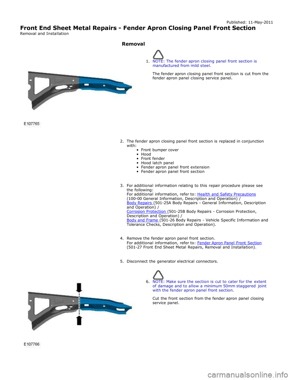
1. NOTE: The fender apron closing panel front section is
manufactured from mild steel.
The fender apron closing panel front section is cut from the
fender apron panel closing service panel.
2. The fender apron closing panel front section is replaced in conjunction
with:
Front bumper cover
Hood
Front fender
Hood latch panel
Fender apron panel front extension
Fender apron panel front section
3. For additional information relating to this repair procedure please see
the following:
For additional information, refer to: Health and Safety Precautions (100-00 General Information, Description and Operation) /
Body Repairs (501-25A Body Repairs - General Information, Description and Operation) /
Corrosion Protection (501-25B Body Repairs - Corrosion Protection, Description and Operation) /
Body and Frame (501-26 Body Repairs - Vehicle Specific Information and Tolerance Checks, Description and Operation).
4. Remove the fender apron panel front section.
For additional information, refer to: Fender Apron Panel Front Section (501-27 Front End Sheet Metal Repairs, Removal and Installation).
5. Disconnect the generator electrical connectors.
6. NOTE: Make sure the section is cut to cater for the extent
of damage and to allow a minimum 50mm staggered joint
with the fender apron panel front section.
Cut the front section from the fender apron panel closing
service panel.
Page 2759 of 3039
Front End Sheet Metal Repairs - Fender Apron Panel
Removal and Installation
Removal Published: 11-May-2011
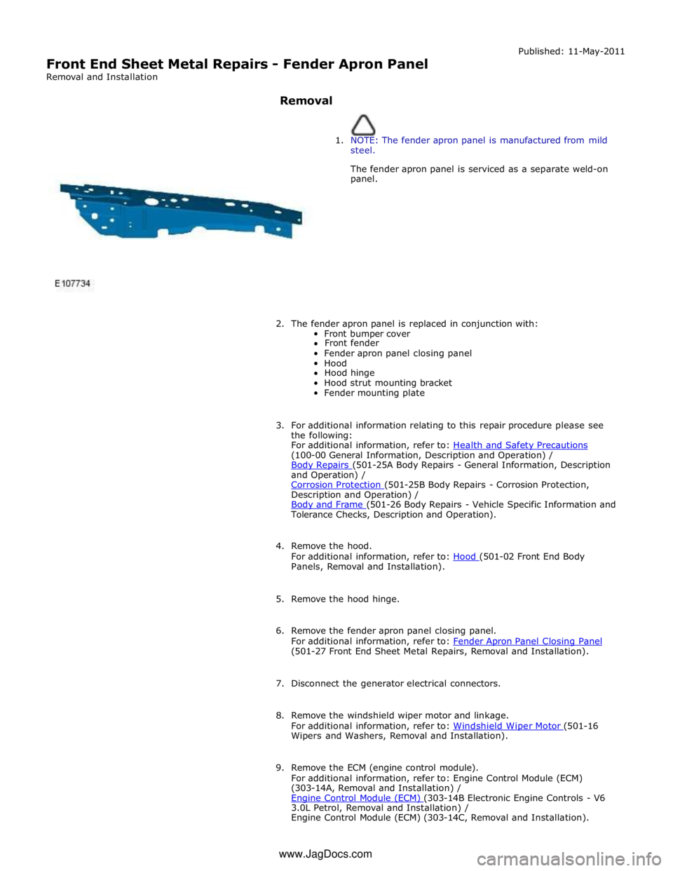
1. NOTE: The fender apron panel is manufactured from mild
steel.
The fender apron panel is serviced as a separate weld-on
panel.
2. The fender apron panel is replaced in conjunction with:
Front bumper cover
Front fender
Fender apron panel closing panel
Hood
Hood hinge
Hood strut mounting bracket
Fender mounting plate
3. For additional information relating to this repair procedure please see
the following:
For additional information, refer to: Health and Safety Precautions (100-00 General Information, Description and Operation) /
Body Repairs (501-25A Body Repairs - General Information, Description and Operation) /
Corrosion Protection (501-25B Body Repairs - Corrosion Protection, Description and Operation) /
Body and Frame (501-26 Body Repairs - Vehicle Specific Information and Tolerance Checks, Description and Operation).
4. Remove the hood.
For additional information, refer to: Hood (501-02 Front End Body Panels, Removal and Installation).
5. Remove the hood hinge.
6. Remove the fender apron panel closing panel.
For additional information, refer to: Fender Apron Panel Closing Panel (501-27 Front End Sheet Metal Repairs, Removal and Installation).
7. Disconnect the generator electrical connectors.
8. Remove the windshield wiper motor and linkage.
For additional information, refer to: Windshield Wiper Motor (501-16 Wipers and Washers, Removal and Installation).
9. Remove the ECM (engine control module).
For additional information, refer to: Engine Control Module (ECM)
(303-14A, Removal and Installation) /
Engine Control Module (ECM) (303-14B Electronic Engine Controls - V6 3.0L Petrol, Removal and Installation) /
Engine Control Module (ECM) (303-14C, Removal and Installation). www.JagDocs.com
Page 2766 of 3039
Published: 11-May-2011
Front End Sheet Metal Repairs - Fender Apron Panel Closing Panel
Removal and Installation
Removal
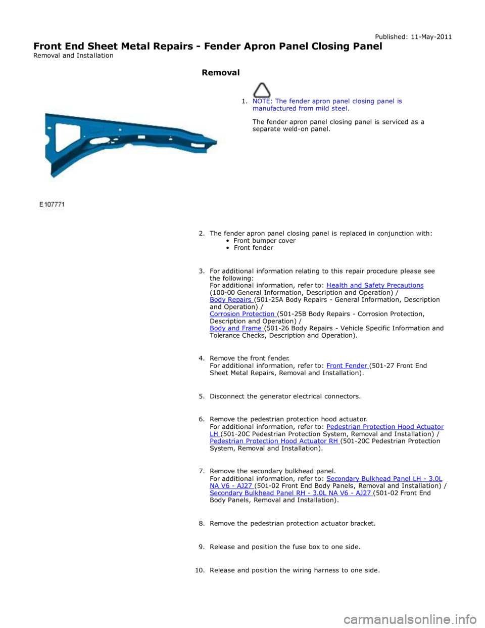
1. NOTE: The fender apron panel closing panel is
manufactured from mild steel.
The fender apron panel closing panel is serviced as a
separate weld-on panel.
2. The fender apron panel closing panel is replaced in conjunction with:
Front bumper cover
Front fender
3. For additional information relating to this repair procedure please see
the following:
For additional information, refer to: Health and Safety Precautions (100-00 General Information, Description and Operation) /
Body Repairs (501-25A Body Repairs - General Information, Description and Operation) /
Corrosion Protection (501-25B Body Repairs - Corrosion Protection, Description and Operation) /
Body and Frame (501-26 Body Repairs - Vehicle Specific Information and Tolerance Checks, Description and Operation).
4. Remove the front fender.
For additional information, refer to: Front Fender (501-27 Front End Sheet Metal Repairs, Removal and Installation).
5. Disconnect the generator electrical connectors.
6. Remove the pedestrian protection hood actuator.
For additional information, refer to: Pedestrian Protection Hood Actuator LH (501-20C Pedestrian Protection System, Removal and Installation) / Pedestrian Protection Hood Actuator RH (501-20C Pedestrian Protection System, Removal and Installation).
7. Remove the secondary bulkhead panel.
For additional information, refer to: Secondary Bulkhead Panel LH - 3.0L NA V6 - AJ27 (501-02 Front End Body Panels, Removal and Installation) / Secondary Bulkhead Panel RH - 3.0L NA V6 - AJ27 (501-02 Front End Body Panels, Removal and Installation).
8. Remove the pedestrian protection actuator bracket.
9. Release and position the fuse box to one side.
10. Release and position the wiring harness to one side.