2010 JAGUAR XFR door pillar trim
[x] Cancel search: door pillar trimPage 25 of 3039

SpecificationRemoval and InstallationAir Deflector
Cowl Vent Screen (76.10.01)
Engine Rear Undershield
Fender Splash Shield
Hood
Radiator Splash Shield
Secondary Bulkhead Center Panel
Secondary Bulkhead Panel LH - TDV6 3.0L Diesel /V8 5.0L Petrol/V8 S/C 5.0L Petrol
Secondary Bulkhead Panel RH - TDV6 3.0L Diesel /V8 5.0L Petrol/V8 S/C 5.0L Petrol501-03: Body Closures
Removal and InstallationFront Door
Fuel Filler Door
Fuel Filler Door Assembly
Luggage Compartment Lid (76.19.01)
Rear Door501-05: Interior Trim and OrnamentationSpecificationRemoval and InstallationA-Pillar Trim Panel
B-Pillar Lower Trim Panel
B-Pillar Upper Trim Panel
C-Pillar Lower Trim Panel
C-Pillar Trim Panel
Cowl Side Trim Panel
Engine Cover - V8 5.0L Petrol/V8 S/C 5.0L Petrol
Front Door Trim Panel (76.34.01)
Front Scuff Plate Trim Panel
Instrument Panel Speaker Grille
Headliner
Loadspace Scuff Plate Trim Panel
Loadspace Trim Panel
Loadspace Trim Panel LH
Loadspace Trim Panel RH
Luggage Compartment Lid Trim Panel
Parcel Shelf
Rear Door Trim Panel
Rear Scuff Plate Trim Panel
Sun Visor (76.10.48)
Sun Visor Vanity Mirror
Page 2172 of 3039
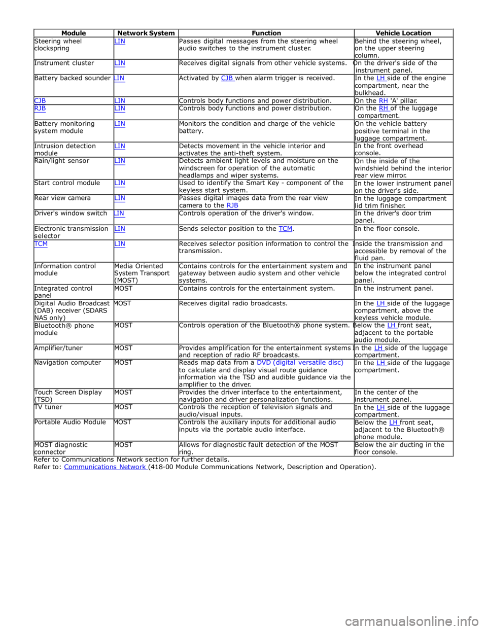
Module Network System Function Vehicle Location
Steering wheel
clockspring LIN Passes digital messages from the steering wheel
audio switches to the instrument cluster. Behind the steering wheel,
on the upper steering
column.
Instrument cluster LIN Receives digital signals from other vehicle systems. On the driver's side of the
instrument panel.
Battery backed sounder LIN Activated by CJB when alarm trigger is received. In the LH side of the engine compartment, near the
bulkhead.
CJB LIN Controls body functions and power distribution. On the RH 'A' pillar.
RJB LIN Controls body functions and power distribution. On the RH of the luggage compartment.
Battery monitoring
system module
Intrusion detection
module LIN Monitors the condition and charge of the vehicle
battery.
LIN Detects movement in the vehicle interior and
activates the anti-theft system. On the vehicle battery
positive terminal in the
luggage compartment.
In the front overhead
console.
Rain/light sensor LIN Detects ambient light levels and moisture on the
windscreen for operation of the automatic
headlamps and wiper systems.
Start control module LIN Used to identify the Smart Key - component of the
keyless start system.
Rear view camera LIN Passes digital images data from the rear view
camera to the RJB On the inside of the
windshield behind the interior
rear view mirror.
In the lower instrument panel
on the driver's side.
In the luggage compartment
lid trim finisher.
Driver's window switch LIN Controls operation of the driver's window. In the driver's door trim
panel.
Electronic transmission
selector LIN Sends selector position to the TCM. In the floor console. TCM LIN Receives selector position information to control the Inside the transmission and
Information control
module
Media Oriented
System Transport
(MOST) transmission.
Contains controls for the entertainment system and
gateway between audio system and other vehicle
systems. accessible by removal of the
fluid pan.
In the instrument panel
below the integrated control
panel.
Integrated control
panel MOST Contains controls for the entertainment system. In the instrument panel.
Digital Audio Broadcast MOST Receives digital radio broadcasts. In the LH side of the luggage (DAB) receiver (SDARS
NAS only)
Bluetooth® phone
module compartment, above the
keyless vehicle module.
MOST Controls operation of the Bluetooth® phone system. Below the LH front seat, adjacent to the portable
audio module.
Amplifier/tuner MOST Provides amplification for the entertainment systems In the LH side of the luggage and reception of radio RF broadcasts.
Navigation computer MOST Reads map data from a DVD (digital versatile disc)
to calculate and display visual route guidance
information via the TSD and audible guidance via the
amplifier to the driver. compartment.
In the LH side of the luggage compartment.
Touch Screen Display
(TSD) MOST Provides the driver interface to the entertainment,
navigation and driver personalization functions. In the center of the
instrument panel.
TV tuner MOST Controls the reception of television signals and
audio/visual inputs.
Portable Audio Module MOST Controls the auxiliary inputs for additional audio
inputs via the portable audio interface. In the LH side of the luggage compartment.
Below the LH front seat, adjacent to the Bluetooth®
phone module.
MOST diagnostic
connector MOST Allows for diagnostic fault detection of the MOST
ring. Below the air ducting in the
floor console.
Refer to Communications Network section for further details.
Refer to: Communications Network (418-00 Module Communications Network, Description and Operation).
Page 2211 of 3039
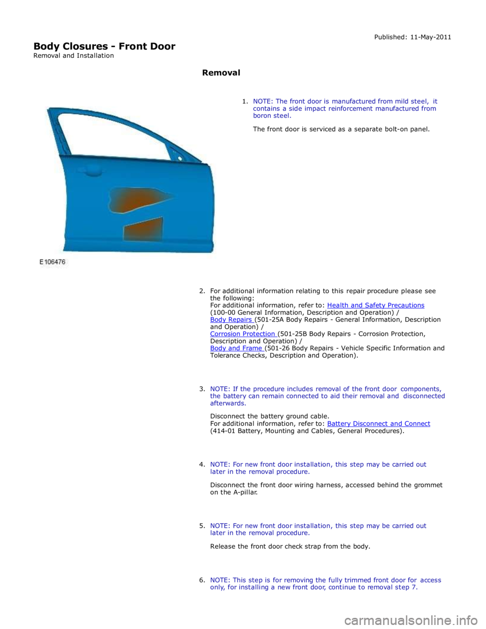
(100-00 General Information, Description and Operation) /
Body Repairs (501-25A Body Repairs - General Information, Description and Operation) /
Corrosion Protection (501-25B Body Repairs - Corrosion Protection, Description and Operation) /
Body and Frame (501-26 Body Repairs - Vehicle Specific Information and Tolerance Checks, Description and Operation).
3. NOTE: If the procedure includes removal of the front door components,
the battery can remain connected to aid their removal and disconnected
afterwards.
Disconnect the battery ground cable.
For additional information, refer to: Battery Disconnect and Connect (414-01 Battery, Mounting and Cables, General Procedures).
4. NOTE: For new front door installation, this step may be carried out
later in the removal procedure.
Disconnect the front door wiring harness, accessed behind the grommet
on the A-pillar.
5. NOTE: For new front door installation, this step may be carried out
later in the removal procedure.
Release the front door check strap from the body.
6. NOTE: This step is for removing the fully trimmed front door for access
only, for installing a new front door, continue to removal step 7.
Page 2221 of 3039
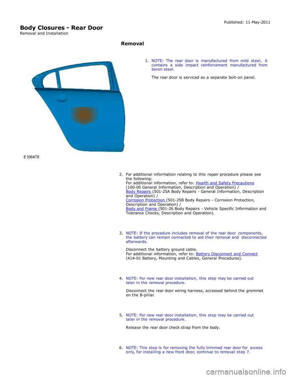
(100-00 General Information, Description and Operation) /
Body Repairs (501-25A Body Repairs - General Information, Description and Operation) /
Corrosion Protection (501-25B Body Repairs - Corrosion Protection, Description and Operation) /
Body and Frame (501-26 Body Repairs - Vehicle Specific Information and Tolerance Checks, Description and Operation).
3. NOTE: If the procedure includes removal of the rear door components,
the battery can remain connected to aid their removal and disconnected
afterwards.
Disconnect the battery ground cable.
For additional information, refer to: Battery Disconnect and Connect (414-01 Battery, Mounting and Cables, General Procedures).
4. NOTE: For new rear door installation, this step may be carried out
later in the removal procedure.
Disconnect the rear door wiring harness, accessed behind the grommet
on the B-pillar.
5. NOTE: For new rear door installation, this step may be carried out
later in the removal procedure.
Release the rear door check strap from the body.
6. NOTE: This step is for removing the fully trimmed rear door for access
only, for installing a new front door, continue to removal step 7.
Page 2494 of 3039
door modules.
Locking of the vehicle is performed by pressing one of the buttons located on each exterior door handle, with the Smart Key
within a one meter range of the vehicle. When the door handle button is pressed, the keyless vehicle module transmits a
low-frequency signal via the low-frequency handle antenna to the Smart Key. The Smart Key transmits a radio frequency signal
which is verified by the keyless vehicle module and allows the doors to be locked or double locked and the alarm system to be
armed.
To double lock the vehicle, the button on the exterior door handle must be pressed twice within three seconds, with the Smart
Key within one meter range of the vehicle.
If a door, engine-compartment lid or the luggage compartment lid is ajar when an attempt to lock the vehicle is made, an error
tone is emitted and no locking action will occur.
Refer to: Anti-Theft - Active (419-01A Anti-Theft - Active, Description and Operation).
Engine Compartment Lid Latches Component Description
Two engine-compartment lid latches are located on the front crossmember. An engine-compartment lid release lever is located
below the instrument panel on the left-hand 'A' pillar and is connected with a cable to the latches. An engine-compartment lid
ajar switch is integrated in the engine-compartment lid latch.
Door Latches
The door latches are located at the rear of each door and engage with a striker on the adjacent pillar. Each door latch motor
assembly contains micro-switches for lock, unlock and door ajar. Motors provide for the central door locking and the double
locking feature. The electrical control for the door latch components is provided by the CJB and RJB via the driver's and
passenger door modules.
The interior door handles are connected by a cable to the latch release mechanisms. The interior door handles also incorporate
a locking facility to allow the doors to be locked from inside the vehicle when all the doors are closed. If a door is ajar the
locking feature is inhibited.
Luggage Compartment Lid Latch
The luggage compartment latch is attached to the bottom of the lid. The latch can be released electrically by pressing the
interior release button located on the outboard side of driver's lower knee bolster; a release button is also provided on the
Smart Key. There is also a release switch on the underside of the luggage compartment lid finisher.
On NAS vehicles an emergency release cable is attached to the latch. This allows the latch to be manually opened by pulling a
handle located in the luggage compartment lid interior trim.
Fuel Filler Door
The fuel filler door is electrically locked by a motor located on the fuel door housing. The fuel door is locked when the vehicle
is locked and alarmed. The fuel door can be opened when the vehicle is unlocked or locked:
via an interior handle,
via drive-a-way locking,
via the lock switch on the fascia,
via the external door key barrel. www.JagDocs.com
Page 2735 of 3039
Side windows
In the case of side windows, the same problems can arise as for a windscreen. The same corrective actions must therefore be
used.
Door seal
Diagnosis:
- Water ingress in the lower part of the interior door trim or in the rocker panel area.
Cause:
- The water shield fitted behind the interior door trim exists to drain off water that has entered the door via the
drainage holes, either downwards or outwards. If the water shield seal is damaged or has been fitted incorrectly,
then water can get into the passenger compartment.
- In addition to this, the drainage holes can become clogged with leaves, dirt or excess cavity protection agents.
Water gathers in the door and ingresses into the passenger compartment.
- Check water shield for damage or correct fitting.
- If the water shield needs to be re-bonded, then approved seam sealer should be used.
- Before the water shield is installed, the drainage holes must be checked for unhindered flow.
Door seals
Diagnosis:
- Ingress of water into the rocker panel area
Cause:
- Insufficient clamping load between seal and door.
Corrective action:
NOTE: When adjusting the clamping load, the profile alignment of the relevant components must always be taken
into consideration.
NOTE: Do not realign the flange too far in the direction of the door, as this can reduce the bearing surface of the
seal to the door.
- Check clamping load:
- The easiest way to check the clamping load of a seal to the respective bearing surface is by means of a paper
strip test. This consists of trapping strips of paper at various points between the door and the seal, and fully
closing the door. If it is possible to pull out the paper with no great resistance, then the clamping load is too
low.
- Adjust the clamping load:
- The clamping load is normally adjusted using the striker. When doing so, the edge alignment from the door to
the side panel, or from the front door to the rear door must be taken into account.
- Another setting method is to realign the panel flange for the seal mounting. The clamping load is increased by
moving the flange towards the door.
- Check the bearing surface:
- Apply chalk evenly to the surface of the seal. Evenly coat the bearing surface of the door with Vaseline.
- Close the door fully, the lock must engage. Open the door. The imprint of the chalk (bearing surface) can be
identified in the film of Vaseline.
- The bearing surface should be at least 5mm across at all points.
Other causes:
- The door seal must completely seal the door where it meets the bodywork.
- Water can ingress directly or indirectly into the interior of the vehicle if the seal is damaged at any point.
Corrective action:
- A damaged or worn door seal must always be renewed in full.
- When renewing the seal, the following must be taken into account:
- Always fit the seal first in the area of the narrow radii (corner points).
- Next, secure the seal to the flange evenly by tapping lightly with a rubber hammer. The installed seal must not
be kinked at any point.
NOTE: The prescribed length of a seal must not be shortened.
Other cause:
- The door seal is attached to the welded flange all the way round. If this welded flange is uneven or damaged at
any point (usually in areas with small radii) then this point could be subject to leaks.
- A stretched seal carrier can also cause a leak.
- In both cases, water gets into the vehicle interior under the seal carrier.
Corrective action:
- Align the deformed welded flange using a hammer and anvil block, prevent and, if necessary, repair any paint
damage.
Sliding roof/tilting roof
Diagnosis:
- Ingress of water at sliding roof aperture
Cause:
- The sliding roof/tilting roof is installed in a water trap. The water drains off via the water trap, water drain holes
and drain hoses. The drain hoses lead downwards on both sides via the A-pillar and B-pillar.
- The drain holes or drain hoses can become clogged with leaves, dirt, underbody protection and so on.
Corrective action:
Page 2843 of 3039
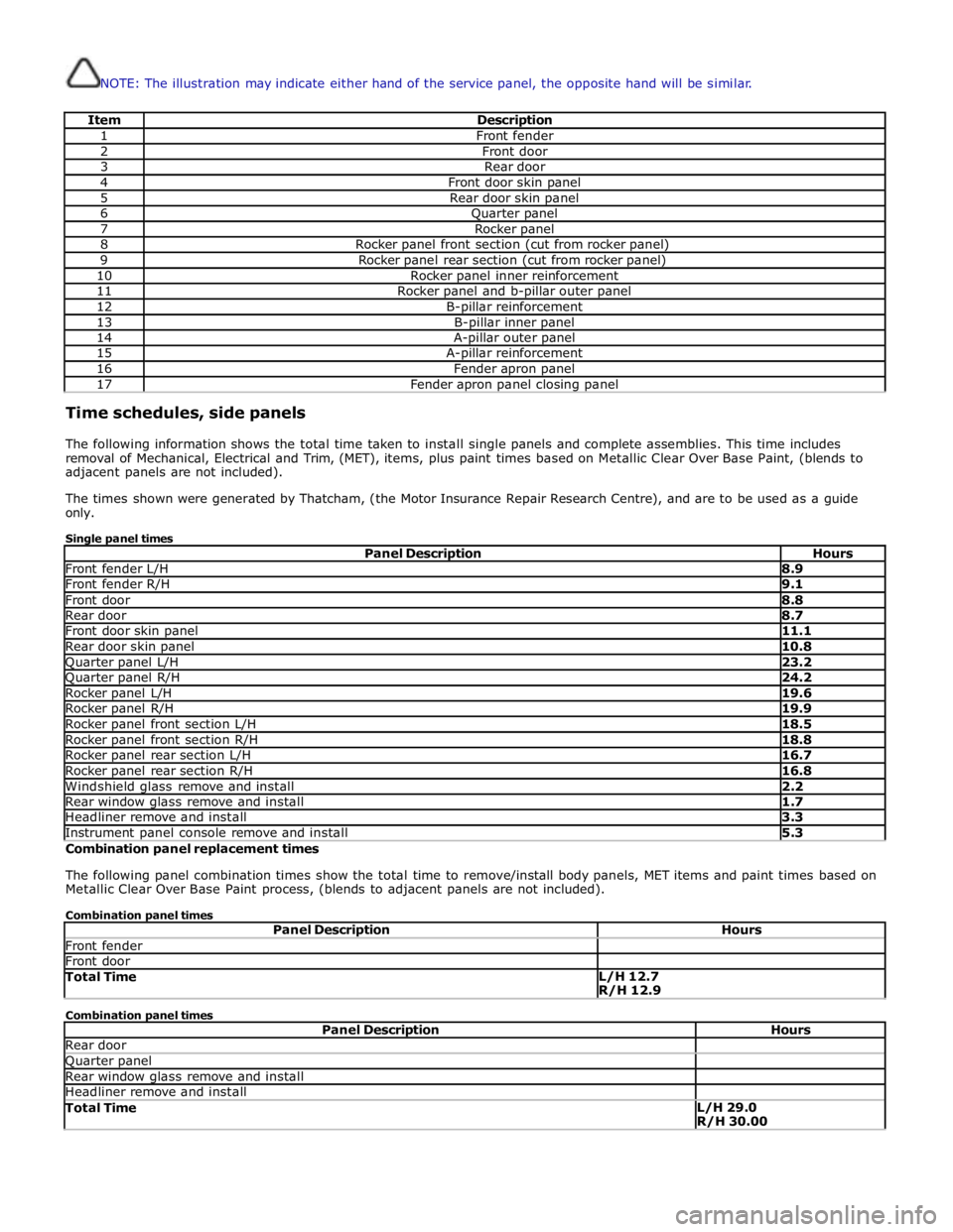
NOTE: The illustration may indicate either hand of the service panel, the opposite hand will be similar.
Item Description 1 Front fender 2 Front door 3 Rear door 4 Front door skin panel 5 Rear door skin panel 6 Quarter panel 7 Rocker panel 8 Rocker panel front section (cut from rocker panel) 9 Rocker panel rear section (cut from rocker panel) 10 Rocker panel inner reinforcement 11 Rocker panel and b-pillar outer panel 12 B-pillar reinforcement 13 B-pillar inner panel 14 A-pillar outer panel 15 A-pillar reinforcement 16 Fender apron panel 17 Fender apron panel closing panel Time schedules, side panels
The following information shows the total time taken to install single panels and complete assemblies. This time includes
removal of Mechanical, Electrical and Trim, (MET), items, plus paint times based on Metallic Clear Over Base Paint, (blends to
adjacent panels are not included).
The times shown were generated by Thatcham, (the Motor Insurance Repair Research Centre), and are to be used as a guide
only.
Single panel times
Panel Description Hours Front fender L/H 8.9 Front fender R/H 9.1 Front door 8.8 Rear door 8.7 Front door skin panel 11.1 Rear door skin panel 10.8 Quarter panel L/H 23.2 Quarter panel R/H 24.2 Rocker panel L/H 19.6 Rocker panel R/H 19.9 Rocker panel front section L/H 18.5 Rocker panel front section R/H 18.8 Rocker panel rear section L/H 16.7 Rocker panel rear section R/H 16.8 Windshield glass remove and install 2.2 Rear window glass remove and install 1.7 Headliner remove and install 3.3 Instrument panel console remove and install 5.3 Combination panel replacement times
The following panel combination times show the total time to remove/install body panels, MET items and paint times based on
Metallic Clear Over Base Paint process, (blends to adjacent panels are not included).
Combination panel times
Panel Description Hours Front fender Front door Total Time L/H 12.7
R/H 12.9 Combination panel times
Panel Description Hours Rear door Quarter panel Rear window glass remove and install Headliner remove and install Total Time L/H 29.0
R/H 30.00
Page 2849 of 3039
Installation
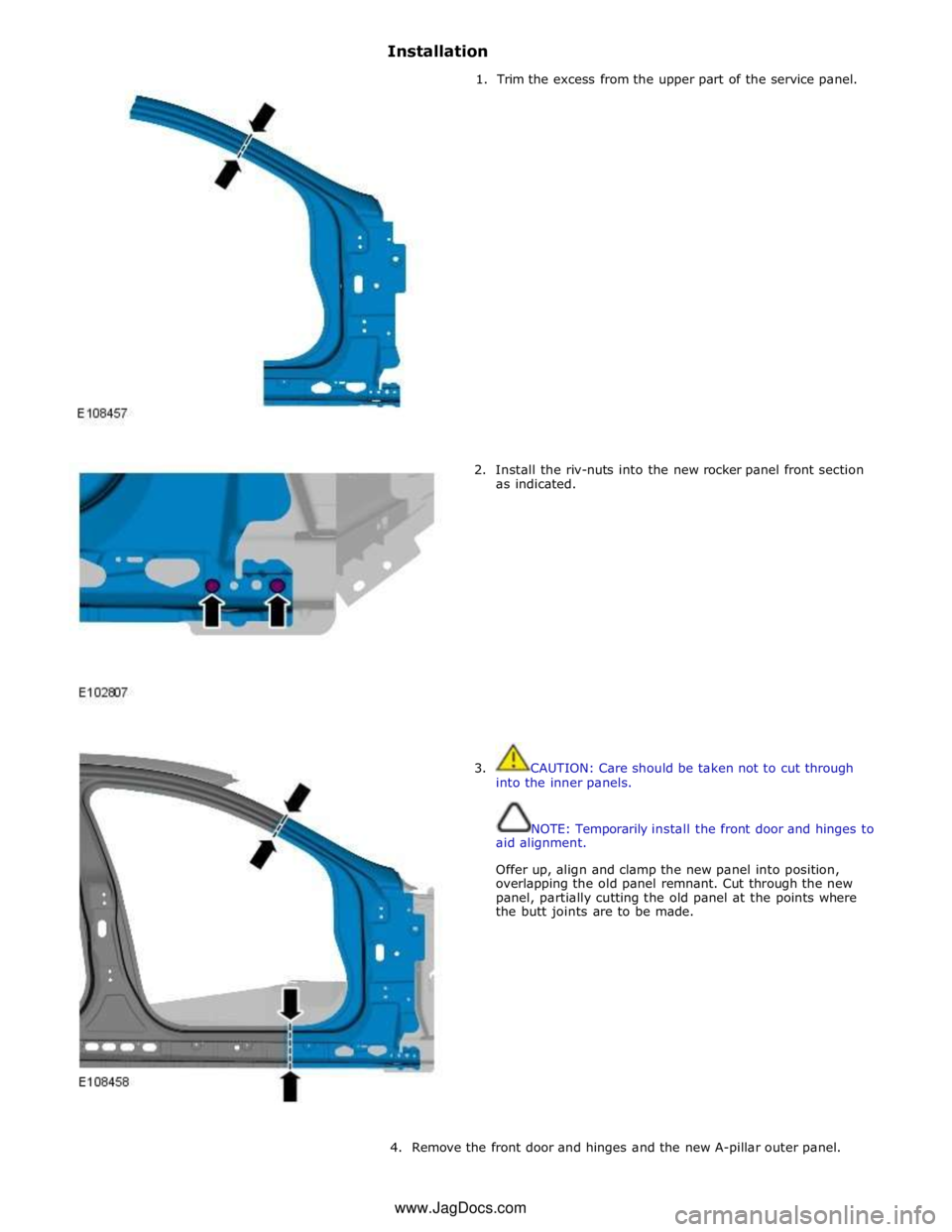
1. Trim the excess from the upper part of the service panel.
2. Install the riv-nuts into the new rocker panel front section
as indicated.
3. CAUTION: Care should be taken not to cut through
into the inner panels.
NOTE: Temporarily install the front door and hinges to
aid alignment.
Offer up, align and clamp the new panel into position,
overlapping the old panel remnant. Cut through the new
panel, partially cutting the old panel at the points where
the butt joints are to be made.
4. Remove the front door and hinges and the new A-pillar outer panel. www.JagDocs.com