2010 JAGUAR XFR service
[x] Cancel search: servicePage 2109 of 3039
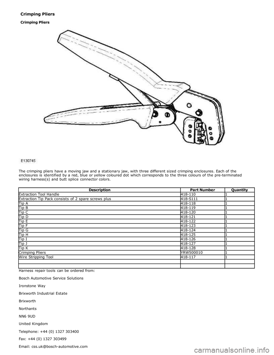
Extraction Tool Handle 418-110 1 Extraction Tip Pack consists of 2 spare screws plus 418-S111 1 Tip A 418-118 1 Tip B 418-119 1 Tip C 418-120 1 Tip D 418-121 1 Tip E 418-122 1 Tip F 418-123 1 Tip G 418-124 1 Tip H 418-125 1 Tip I 418-126 1 Tip J 418-127 1 Tip K 418-128 1 Crimping Pliers YRW500010 1 Wire Stripping Tool 418-117 1 Harness repair tools can be ordered from:
Bosch Automotive Service Solutions
Ironstone Way
Brixworth Industrial Estate
Brixworth
Northants
NN6 9UD
United Kingdom
Telephone: +44 (0) 1327 303400
Fax: +44 (0) 1327 303499
Email: [email protected] Crimping Pliers
Crimping Pliers
Page 2127 of 3039

Check DDW for open campaigns. Refer to the corresponding bulletins and SSMs which may be valid for the specific
customer complaint and carry out the recommendations as required.
DTC Description Possible Causes Action B1087-83
LIN Bus "A" - Value of
signal protection
calculation incorrect
Checksum of the received LIN
frame from battery backed
sounder, roof header console,
and/or rain/light sensor is
incorrect
Check operation of rain/light sensor by
covering sensor or applying water to screen,
install a new sensor as required B1087-88 LIN Bus "A" - Bus off
Bus off. Battery backed sounder,
roof header console, and/or
rain/light sensor LIN circuit -
short to ground, power
Carry out any pinpoint tests associated with
this DTC using the manufacturer approved
diagnostic system. Refer to the electrical
circuit diagrams and check battery backed
sounder, roof header console, and rain/light
sensor LIN circuit for short to ground, power B108F-23
Cabin Lock/Unlock
Switch - Signal stuck
low
Cabin lock/unlock switch signal
stuck
Switch pressed for longer than
20 seconds
Switch circuit short circuit to
power or ground
Switch failure
Check the switch operation and
serviceability. Refer to the electrical circuit
diagrams and check the switch circuit B109C-11
Front Courtesy Light -
Circuit short to ground
Short to ground
Refer to the electrical circuit diagrams and
test front courtesy light circuit for short to
ground B109C-15
Front Courtesy Light -
Circuit short to battery
or open
Short to power or open circuit
Refer to the electrical circuit diagrams and
test front courtesy light circuit for short to
power or open circuit B10EB-11
Driver Door Double
Locking Motor - Circuit
short to ground
Driver door double locking motor
control circuit - short to ground
Refer to the electrical circuit diagrams and
test driver door double locking motor control
circuit for short ground B10EB-15
Driver Door Double
Locking Motor - Circuit
short to battery or open
Driver door double locking motor
control circuit - short to power,
open circuit
Carry out any pinpoint tests associated with
this DTC using the manufacturer approved
diagnostic system. Refer to the electrical
circuit diagrams and test driver door double
locking motor control circuit for short to
power or open circuit B10EC-11
Passenger Door Double
Locking Motor - Circuit
short to ground
Passenger door double locking
motor control circuit - short to
ground
Refer to the electrical circuit diagrams and
test passenger door double locking motor
control circuit for short ground B10EC-15
Passenger Door Double
Locking Motor - Circuit
short to battery or open
Passenger door double locking
motor control circuit - short to
power, open circuit
Carry out any pinpoint tests associated with
this DTC using the manufacturer approved
diagnostic system. Refer to the electrical
circuit diagrams and test passenger door
double locking motor control circuit for short
to power or open circuit B10ED-11
Rear Door Driver Side
Double Locking Motor -
Circuit short to ground
Rear door driver side double
locking motor control circuit -
short to ground
Refer to the electrical circuit diagrams and
test rear door driver side double locking
motor control circuit for short ground B10ED-15
Rear Door Driver Side
Double Locking Motor -
Circuit short to battery
or open
Rear door driver side double
locking motor control circuit -
short to power, open circuit
Carry out any pinpoint tests associated with
this DTC using the manufacturer approved
diagnostic system. Refer to the electrical
circuit diagrams and test rear door driver
side double locking motor control circuit for
short power, open circuit
Page 2197 of 3039
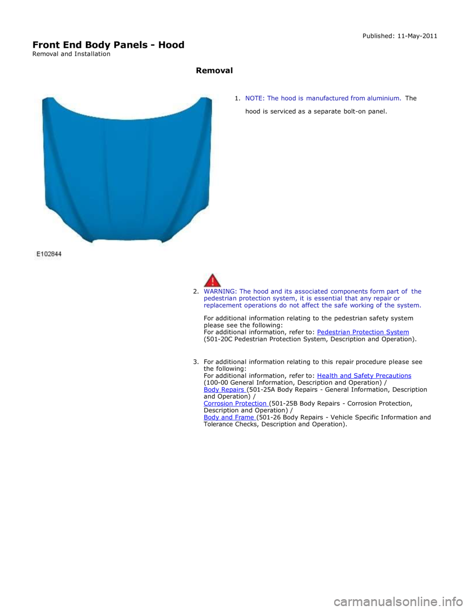
Front End Body Panels - Hood
Removal and Installation Published: 11-May-2011
Removal
1. NOTE: The hood is manufactured from aluminium. The
hood is serviced as a separate bolt-on panel.
2. WARNING: The hood and its associated components form part of the
pedestrian protection system, it is essential that any repair or
replacement operations do not affect the safe working of the system.
For additional information relating to the pedestrian safety system
please see the following:
For additional information, refer to: Pedestrian Protection System (501-20C Pedestrian Protection System, Description and Operation).
3. For additional information relating to this repair procedure please see
the following:
For additional information, refer to: Health and Safety Precautions (100-00 General Information, Description and Operation) /
Body Repairs (501-25A Body Repairs - General Information, Description and Operation) /
Corrosion Protection (501-25B Body Repairs - Corrosion Protection, Description and Operation) /
Body and Frame (501-26 Body Repairs - Vehicle Specific Information and Tolerance Checks, Description and Operation).
Page 2328 of 3039
Seating - Seats
Diagnosis and Testing
Principle of Operation Published: 18-Apr-2013
For a detailed description of the seats and seat operation, refer to the relevant Description and Operation section in the
workshop manual. REFER to: (501-10 Seating)
Seats (Description and Operation), Seats (Description and Operation), Seats (Description and Operation).
Inspection and Verification
CAUTION: Diagnosis by substitution from a donor vehicle is NOT acceptable. Substitution of control modules does not
guarantee confirmation of a fault, and may also cause additional faults in the vehicle being tested and/or the donor vehicle.
NOTE: Prior to carrying out any diagnosis, ensure the vehicle battery is in a good serviceable condition, refer to the
battery care manual.
1. Verify the customer concern.
2. Visually inspect for obvious signs of damage and system integrity.
Visual Inspection
Mechanical Electrical
Security, condition and correct installation of seat components and fixings
Fuses
Harnesses for damage/corrosion
Electrical connectors
Damaged/corroded pins
3. If an obvious cause for an observed or reported concern is found, correct the cause (if possible) before proceeding to
the next step.
4. If the cause is not visually evident, verify the concern and refer to the Symptom Chart, alternatively, check for
Diagnostic Trouble Codes (DTCs) and refer to the DTC Index.
5. Check DDW for open campaigns. Refer to the corresponding bulletins and SSM's which may be valid for the specific
customer complaint and carry out the recommendations as needed.
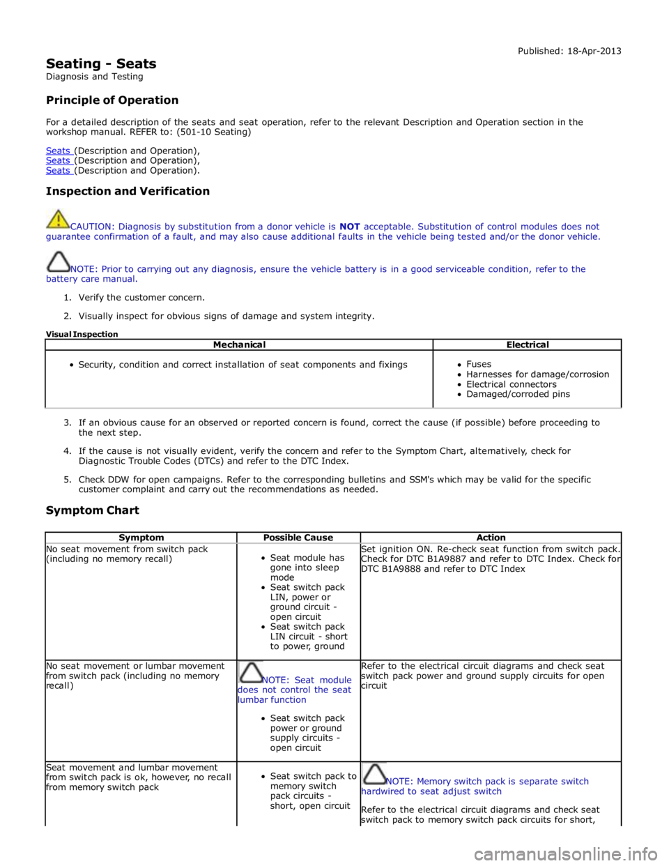
Symptom Chart
Symptom Possible Cause Action No seat movement from switch pack
(including no memory recall)
Seat module has
gone into sleep
mode
Seat switch pack
LIN, power or
ground circuit -
open circuit
Seat switch pack
LIN circuit - short
to power, ground Set ignition ON. Re-check seat function from switch pack.
Check for DTC B1A9887 and refer to DTC Index. Check for
DTC B1A9888 and refer to DTC Index No seat movement or lumbar movement
from switch pack (including no memory
recall)
NOTE: Seat module
does not control the seat
lumbar function
Seat switch pack
power or ground
supply circuits -
open circuit Refer to the electrical circuit diagrams and check seat
switch pack power and ground supply circuits for open
circuit Seat movement and lumbar movement
from switch pack is ok, however, no recall
from memory switch pack
Seat switch pack to
memory switch
pack circuits -
short, open circuit
NOTE: Memory switch pack is separate switch
hardwired to seat adjust switch
Refer to the electrical circuit diagrams and check seat
switch pack to memory switch pack circuits for short,
Page 2334 of 3039
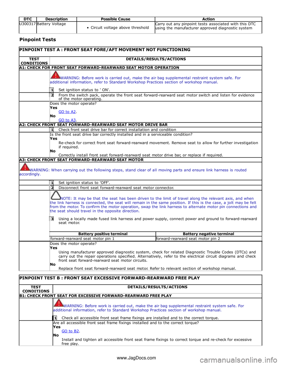
DTC Description Possible Cause Action U300317 Battery Voltage
Circuit voltage above threshold Carry out any pinpoint tests associated with this DTC
using the manufacturer approved diagnostic system Pinpoint Tests
PINPOINT TEST A : FRONT SEAT FORE/AFT MOVEMENT NOT FUNCTIONING TEST
CONDITIONS DETAILS/RESULTS/ACTIONS A1: CHECK FOR FRONT SEAT FORWARD-REARWARD SEAT MOTOR OPERATION
WARNING: Before work is carried out, make the air bag supplemental restraint system safe. For
additional information, refer to Standard Workshop Practices section of workshop manual. 1 Set ignition status to ' ON'. 2 From the switch pack, operate the front seat forward-rearward seat motor switch and listen for evidence of the motor operating. Does the motor operate? Yes
GO to A2. No
GO to A3. A2: CHECK FRONT SEAT FORWARD-REARWARD SEAT MOTOR DRIVE BAR 1 Check front seat drive bar for correct installation and condition Is the front seat drive bar correctly installed and in a serviceable condition? Yes
Re-check for correct front seat forward-rearward movement. Remove seat to allow for further investigation
if required.
No
Correctly install front seat forward-rearward seat motor drive bar, or replace if required. A3: CHECK FRONT SEAT FORWARD-REARWARD SEAT MOTOR
WARNING: When carrying out the following steps, stand clear of all moving parts and ensure link harness is routed
accordingly. 1 Set ignition status to 'OFF'. 2 Disconnect front seat forward-rearward seat motor connector.
NOTE: It may be that the seat has been driven to the limit of travel along the relevant axis, and when
the link harness is connected, the seat will remain in the same position. If this is the case, a jolt may be felt
from the motor. To confirm the motor operation, swap the link harness to alternate motor pin connections and
the seat should travel in the opposite direction. 3 Using a locally made fused link harness and power supply, connect power and ground to forward-rearward seat motor. Battery positive terminal Battery negative terminal forward-rearward seat motor pin 1 forward-rearward seat motor pin 2 Does the motor operate? Yes
Using manufacturer approved diagnostic system, check for related Diagnostic Trouble Codes (DTCs) and
carry out the repair operations specified. Alternatively, refer to the electrical circuit diagrams and check
front seat forward-rearward seat motor circuits.
No
Replace front seat forward-rearward seat motor. Refer to relevant section of workshop manual.
PINPOINT TEST B : FRONT SEAT EXCESSIVE FORWARD-REARWARD FREE PLAY TEST
CONDITIONS DETAILS/RESULTS/ACTIONS B1: CHECK FRONT SEAT FOR EXCESSIVE FORWARD-REARWARD FREE PLAY
WARNING: Before work is carried out, make the air bag supplemental restraint system safe. For
additional information, refer to Standard Workshop Practices section of workshop manual. 1 Check all accessible front seat frame fixings are installed and to the correct torque. Are all accessible front seat frame fixings installed and to the correct torque?
Yes
GO to B2. No
Install and tighten all accessible front seat frame fixings to correct torque and re-check for excessive
free play. www.JagDocs.com
Page 2335 of 3039
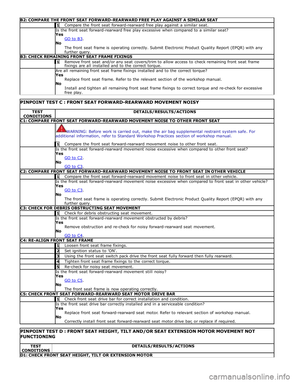
B2: COMPARE THE FRONT SEAT FORWARD-REARWARD FREE PLAY AGAINST A SIMILAR SEAT 1 Compare the front seat forward-rearward free play against a similar seat. Is the front seat forward-rearward free play excessive when compared to a similar seat?
Yes
GO to B3. No
The front seat frame is operating correctly. Submit Electronic Product Quality Report (EPQR) with any
further query. B3: CHECK REMAINING FRONT SEAT FRAME FIXINGS 1 Remove front seat and/or any seat covers/trim to allow access to check remaining front seat frame fixings are all installed and to the correct torque. Are all remaining front seat frame fixings installed and to the correct torque?
Yes
Replace front seat frame. Refer to the relevant section of the workshop manual.
No
Install and tighten all remaining front seat frame fixings to correct torque and re-check for excessive
free play.
PINPOINT TEST C : FRONT SEAT FORWARD-REARWARD MOVEMENT NOISY TEST
CONDITIONS DETAILS/RESULTS/ACTIONS C1: COMPARE FRONT SEAT FORWARD-REARWARD MOVEMENT NOISE TO OTHER FRONT SEAT
WARNING: Before work is carried out, make the air bag supplemental restraint system safe. For
additional information, refer to Standard Workshop Practices section of workshop manual. 1 Compare the front seat forward-rearward movement noise to other front seat. Is the front seat forward-rearward movement noise excessive when compared to other front seat?
Yes
GO to C2. No
GO to C3. C2: COMPARE FRONT SEAT FORWARD-REARWARD MOVEMENT NOISE TO FRONT SEAT IN OTHER VEHICLE 1 Compare the front seat forward-rearward movement noise to front seat in other vehicle. Is the front seat forward-rearward movement noise excessive when compared to front seat in other vehicle?
Yes
GO to C3. No
The front seat frame is operating correctly. Submit Electronic Product Quality Report (EPQR) with any
further query. C3: CHECK FOR DEBRIS OBSTRUCTING SEAT MOVEMENT 1 Check for debris obstructing seat movement. Is the front seat forward-rearward movement obstructed by debris?
Yes
Remove obstruction and re-check for noisy forward-rearward seat movement.
No
GO to C4. C4: RE-ALIGN FRONT SEAT FRAME 1 Loosen front seat frame fixings. 2 Set ignition status to 'ON'. 3 Using the front seat switch pack drive the front seat fully forward then fully rearward. 4 Tighten front seat frame fixings to the correct torque. 5 Re-check for noisy seat movement. Is the front seat forward-rearward movement still noisy?
Yes
GO to C5. No
The front seat frame is now operating correctly. C5: CHECK FRONT SEAT FORWARD-REARWARD SEAT MOTOR DRIVE BAR 1 Check front seat drive bar for correct installation and condition. Is the front seat drive bar correctly installed and in a serviceable condition?
Yes
Replace front seat forward-rearward seat motor. Refer to relevant section of workshop manual.
No
Correctly install front seat forward-rearward seat motor drive bar, or replace if required.
PINPOINT TEST D : FRONT SEAT HEIGHT, TILT AND/OR SEAT EXTENSION MOTOR MOVEMENT NOT FUNCTIONING TEST
CONDITIONS DETAILS/RESULTS/ACTIONS D1: CHECK FRONT SEAT HEIGHT, TILT OR EXTENSION MOTOR
Page 2341 of 3039
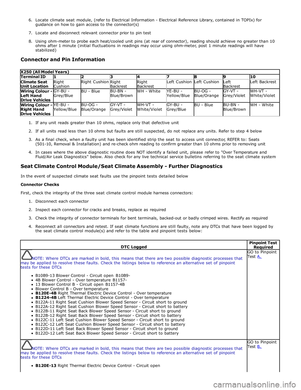
6. Locate climate seat module, (refer to Electrical Information - Electrical Reference Library, contained in TOPIx) for
guidance on how to gain access to the connector(s)
7. Locate and disconnect relevant connector prior to pin test
8. Using ohm-meter to probe each heat/cooled unit pins (at rear of connector), reading should achieve no greater than 10
ohms after 1 minute (initial fluctuations in readings may occur using ohm-meter, post 1 minute readings will have
stabilized)
Connector and Pin Information
X250 (All Model Years) Terminal ID 1 2 3 4 7 8 9 10 Climate Seat
Unit Location Right
Cushion Right Cushion
Right
Backrest Right
Backrest Left Cushion Left Cushion
Left
Backrest Left Backrest Wiring Colour -
Left Hand
Drive Vehicles GY-BU -
Grey/Blue BU - Blue BU-BN -
Blue/Brown WH - White YE-BU - Yellow/Blue BU-OG -
Blue/Orange GY-VT -
Grey/Violet WH-VT -
White/Violet Wiring Colour -
Right Hand
Drive Vehicles YE-BU - Yellow/Blue BU-OG -
Blue/Orange GY-VT -
Grey/Violet WH-VT -
White/Violet GY-BU -
Grey/Blue BU - Blue BU-BN -
Blue/Brown WH - White
1. If any unit reads greater than 10 ohms, replace only that defective unit
2. If all units read less than 10 ohms but faults are still suspected, do not replace any units. Refer to step 4 below
3. As a final check, when a faulty unit has been identified strip the seat to access unit connector, REFER to: Seats
(501-10, Removal & Installation) and re-check ohm reading to confirm greater than 10 ohms prior to removing unit
4. In cases where the above diagnostic routine does NOT identify a failed unit, please refer to "Over Temperature and
Fluid/Air Leak Diagnostics" below. Also check for any live technical service bulletins referring to the seat climate system
Seat Climate Control Module/Seat Climate Assembly - Further Diagnostics
In the event of suspected climate seat faults use the pinpoint tests detailed below
Connector Checks
First, check the integrity of the three seat climate control module harness connectors:
1. Disconnect each connector
2. Inspect each connector for cracks and breaks, replace as required
3. Check the integrity of connector terminals for bent terminals, backed-out or badly crimped wires. Rectify as required
4. Reconnect all connectors and retest. If seat climate functions are still faulty, note any DTCs that have been logged by
the seat climate control module(s) and refer to the table and pinpoint tests below:
DTC Logged Pinpoint Test Required
NOTE: Where DTCs are marked in bold, this means that there are two possible diagnostic processes that
may be applied to resolve these faults. Check the listings below to reference an alternative set of pinpoint
tests for these DTCs
B10B9-13 Blower Control - Circuit open B10B9-
4B Blower Control - Over temperature B1157-
13 Blower Control B - Circuit open B1157-4B
Blower Control B - Over temperature
B120E-4B Right Thermal Electric Device Control - Over temperature
B1224-4B Left Thermal Electric Device Control - Over temperature
B122A-11 Right Seat Cushion Blower Speed Sensor - Circuit short to ground
B122A-12 Right Seat Cushion Blower Speed Sensor - Circuit short to battery
B122B-11 Right Seat Back Blower Speed Sensor - Circuit short to ground
B122B-12 Right Seat Back Blower Speed Sensor - Circuit short to battery
B122C-11 Left Seat Cushion Blower Speed Sensor - Circuit short to ground
B122C-12 Left Seat Cushion Blower Speed Sensor - Circuit short to battery
B122D-11 Left Seat Back Blower Speed Sensor - Circuit short to ground
B122D-12 Left Seat Back Blower Speed Sensor - Circuit short to battery GO to Pinpoint
Test A.
NOTE: Where DTCs are marked in bold, this means that there are two possible diagnostic processes that
may be applied to resolve these faults. Check the listings below to reference an alternative set of pinpoint
tests for these DTCs
B120E-13 Right Thermal Electric Device Control - Circuit open GO to Pinpoint
Test B.
Page 2353 of 3039
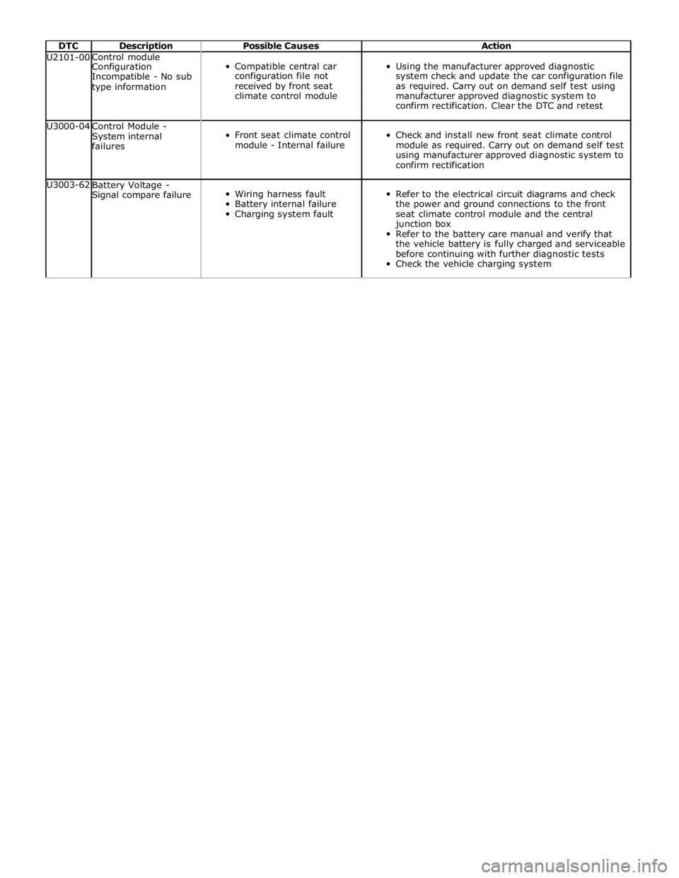
DTC Description Possible Causes Action U2101-00 Control module
Compatible central car
Using the manufacturer approved diagnostic Configuration Incompatible - No sub configuration file not system check and update the car configuration file type information received by front seat as required. Carry out on demand self test using climate control module manufacturer approved diagnostic system to confirm rectification. Clear the DTC and retest U3000-04
Control Module -
System internal
failures
Front seat climate control
module - Internal failure
Check and install new front seat climate control
module as required. Carry out on demand self test
using manufacturer approved diagnostic system to
confirm rectification U3003-62
Battery Voltage -
Signal compare failure
Wiring harness fault
Battery internal failure
Charging system fault
Refer to the electrical circuit diagrams and check
the power and ground connections to the front
seat climate control module and the central
junction box
Refer to the battery care manual and verify that
the vehicle battery is fully charged and serviceable
before continuing with further diagnostic tests
Check the vehicle charging system