Page 655 of 3039

Published: 11-May-2011
Parking Brake and Actuation - Parking Brake Cable Tension Release
General Procedures
Special Tool(s)
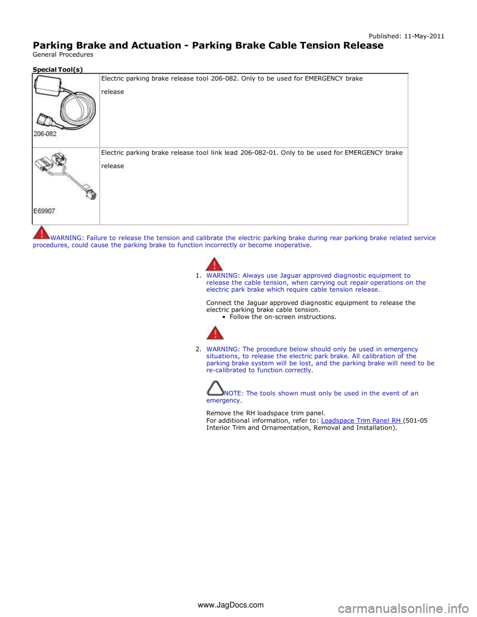
Electric parking brake release tool 206-082. Only to be used for EMERGENCY brake
release
Electric parking brake release tool link lead 206-082-01. Only to be used for EMERGENCY brake
release
WARNING: Failure to release the tension and calibrate the electric parking brake during rear parking brake related service
procedures, could cause the parking brake to function incorrectly or become inoperative.
1. WARNING: Always use Jaguar approved diagnostic equipment to
release the cable tension, when carrying out repair operations on the
electric park brake which require cable tension release.
Connect the Jaguar approved diagnostic equipment to release the
electric parking brake cable tension.
Follow the on-screen instructions.
2. WARNING: The procedure below should only be used in emergency
situations, to release the electric park brake. All calibration of the
parking brake system will be lost, and the parking brake will need to be
re-calibrated to function correctly.
NOTE: The tools shown must only be used in the event of an
emergency.
Remove the RH loadspace trim panel.
For additional information, refer to: Loadspace Trim Panel RH (501-05 Interior Trim and Ornamentation, Removal and Installation). www.JagDocs.com
Page 658 of 3039
Published: 12-Jun-2013
Parking Brake and Actuation - Parking Brake Cable LH TDV6 3.0L Diesel /V8 5.0L Petrol/V8 S/C 5.0L Petrol
Removal and Installation
Removal
WARNING: Failure to release the tension and calibrate the electric parking brake during rear parking brake related service
procedures, could cause the parking brake to function incorrectly or become inoperative.
NOTE: Removal steps in this procedure may contain installation details.
1. Refer to: Parking Brake Cable Tension Release (206-05 Parking Brake and Actuation, General Procedures).
2. WARNING: Make sure to support the vehicle with axle stands.
Raise and support the vehicle.
3. Refer to: Rear Subframe - TDV6 3.0L Diesel (502-00 Uni-Body, Subframe and Mounting System, Removal and Installation).
Refer to: Rear Subframe - V8 5.0L Petrol/V8 S/C 5.0L Petrol (502-00 Uni-Body, Subframe and Mounting System, Removal and Installation).
4.
Page 660 of 3039
Published: 12-Jun-2013
Parking Brake and Actuation - Parking Brake Cable RH TDV6 3.0L Diesel /V8 5.0L Petrol/V8 S/C 5.0L Petrol
Removal and Installation
Removal
WARNING: Failure to release the tension and calibrate the electric parking brake during rear parking brake related service
procedures, could cause the parking brake to function incorrectly or become inoperative.
NOTE: Removal steps in this procedure may contain installation details.
1. Refer to: Parking Brake Cable Tension Release (206-05 Parking Brake and Actuation, General Procedures).
2. WARNING: Make sure to support the vehicle with axle stands.
Raise and support the vehicle.
3. Refer to: Rear Subframe - TDV6 3.0L Diesel (502-00 Uni-Body, Subframe and Mounting System, Removal and Installation).
Refer to: Rear Subframe - V8 5.0L Petrol/V8 S/C 5.0L Petrol (502-00 Uni-Body, Subframe and Mounting System, Removal and Installation).
4.
5. NOTE: Note the fitted position. www.JagDocs.com
Page 663 of 3039
Parking Brake and Actuation - Parking Brake Switch
Removal and Installation
Removal
NOTES: Published: 12-Jun-2013
The parking brake switch is part of the transmission control switch (TCS) assembly and therefore can not be serviced
separately.
Removal steps in this procedure may contain installation details.
1. Refer to: Battery Disconnect and Connect (414-01 Battery, Mounting and Cables, General Procedures).
2. Refer to: Transmission Control Switch (TCS) (307-05A Automatic Transmission/Transaxle External Controls - V6 3.0L Petrol, Removal and
Installation).
Installation
1. CAUTION: Make sure that all diagnostic trouble codes (DTCs) have
been removed after the road test.
To install, reverse the removal procedure.
Page 664 of 3039
Parking Brake and Actuation - Parking Brake Release Actuator
Removal and Installation
Removal Published: 06-May-2014
WARNING: Failure to release the tension and calibrate the electric parking brake during rear parking brake related service
procedures, could cause the parking brake to function incorrectly or become inoperative.
1. Refer to: Parking Brake Cable Tension Release (206-05 Parking Brake and Actuation, General Procedures).
2. WARNING: Make sure to support the vehicle with axle stands.
Raise and support the vehicle.
3. Remove the differential case.
Refer to: Differential Case - TDV6 3.0L Diesel /V8 5.0L Petrol/V8 S/C 5.0L Petrol (205-02 Rear Drive Axle/Differential, Removal and Installation).
Refer to: Differential Case - TD4 2.2L Diesel/TDV6 3.0L Diesel (205-02,
Removal and Installation).
4. Torque: 7 Nm
Page 704 of 3039
Published: 11-May-2011
Anti-Lock Control - Stability Assist - Anti-Lock Brake System (ABS) Module
Removal and Installation
Removal
1. NOTE: The anti-lock braking system (ABS) module mounted to the
hydraulic control unit (HCU) cannot be serviced separately. If the ABS
module requires replacement, the unit must be replaced as a complete
assembly.
Remove the HCU.
For additional information, refer to: Hydraulic Control Unit (HCU)
(206-09, Removal and Installation).
Installation
1. Install the HCU.
For additional information, refer to: Hydraulic Control Unit (HCU)
(206-09, Removal and Installation).
www.JagDocs.com
Page 724 of 3039

2. Free play should be between 0 and 6 mm (0 and 0.24 in) at the steering wheel rim. If the free play exceeds this limit,
either the ball joints are worn, the lower steering column joints are worn or the backlash of the steering gear is
excessive.
CAUTION: DO NOT attempt to adjust the steering gear yoke. Failure to follow this instruction will invalidate the steering
gear warranty.
3. The backlash of the steering gear cannot be adjusted, install a new steering gear if excessive backlash is diagnosed.
4. Grasp the steering wheel firmly and move it up and down and to the left and right without turning the wheel to check
for column bearing wear, steering wheel or steering column.
Power Steering Fluid Condition Check
1. Run the engine for 2 minutes.
2. Check the power steering fluid system level.
3. Observe the color and the odor. The color under normal circumstances should be dark reddish, not brown or black.
4. Using a suitable clean syringe extract a suitable amount of fluid from the reservoir.
5. Allow the fluid to drip onto a facial tissue and examine the stain.
6. If evidence of solid material is found, the power steering fluid system should be drained for further inspection.
7. If fluid contamination or steering component failure is confirmed by the sediment in the power steering fluid system,
refer to Steering Fault Diagnosis by Symptom Charts in this section.
Power Steering Pressure Test
Test Equipment
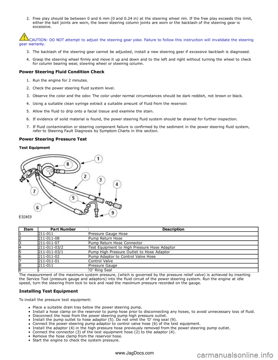
Item Part Number Description 1 211-011 Pressure Gauge Hose 2 211-011-08 Pump Return Hose 3 211-011-07 Pump Return Hose Connector 4 211-011-03/2 Test Equipment to High Pressure Hose Adaptor 5 211-011-03/1 Pump High Pressure Outlet to Hose Adaptor 6 211-011-02 Pump Adaptor to Control Valve Hose 7 211-011-01 Control Valve 8 211-011 Pressure Gauge 9 - 'O' Ring Seal The measurement of the maximum system pressure, (which is governed by the pressure relief valve) is achieved by inserting
the Service Tool (pressure gauge and adaptors) into the fluid circuit of the power steering system. Run the engine at idle
speed, turn the steering from lock to lock and read the maximum pressure recorded on the gauge.
Installing Test Equipment
To install the pressure test equipment:
Place a suitable drain tray below the power steering pump.
Install a hose clamp on the reservoir to pump hose prior to disconnecting any hoses, to avoid unnecessary loss of fluid.
Disconnect the hose from the power steering pump high pressure outlet.
Install the pump outlet to hose adaptor (5). Do not omit the 'O' ring seal (9).
Connect the power steering pump adaptor to control valve hose (6) of the test equipment.
Install the adaptor (4) in the high pressure hose previously removed from the power steering pump outlet.
Connect the connector (3) of the test equipment hose (2) to the adaptor (4).
Remove the hose clamp from the reservoir hose.
Start the engine to check the system pressure. www.JagDocs.com
Page 750 of 3039
1 Bolt and washer (2 off) 2 Rubber mounting (2 off) 3 Cap 4 Reservoir body 5 Return connection 6 Suction hose connection 7 Max/Min level 8 Lanyard The reservoir is located in the engine compartment, on the LH suspension housing. The reservoir is attached to a bracket via 2 rubber mounts, and the bracket is attached to the suspension housing.
The reservoir is a plastic moulding with an integral 80 micron, non-serviceable filter. Two moulded ports at the base of the
reservoir provide for attachment of the fluid supply hose to the power steering pump and fluid return hose from the fluid cooler.
The reservoir is fitted with a removable cap which is screwed 1/4 turn to lock into the reservoir body.
The reservoir has upper and minimum marks moulded on its outside of the body. Fluid Reservoir