2010 JAGUAR XFR compressor
[x] Cancel search: compressorPage 18 of 3039

Speed Control Module
Speed Control Sensor
Speed Control Switch4: Electrical
412: Climate Control System
412-00: Climate Control System - General InformationSpecificationDiagnosis and TestingClimate Control SystemGeneral ProceduresAir Conditioning (A/C) System Recovery, Evacuation and Charging (82.30.30)
Air Conditioning (A/C) System Flushing
Contaminated Refrigerant Handling
Electronic Leak Detection
Fluorescent Dye Leak Detection
Inspection and Assembly Requirements
Manifold Gauge Set Connection
Refrigerant Oil Adding - TDV6 3.0L Diesel /V8 5.0L Petrol/V8 S/C 5.0L Petrol
Refrigerant System Tests
Air Conditioning (A/C) Compressor Commissioning412-01: Climate ControlSpecificationDescription and Operation
Air Distribution and FilteringComponent Location
Overview
System Operation and Component DescriptionHeating and VentilationComponent Location
Overview
System Operation and Component DescriptionAir ConditioningComponent Location
Overview
System Operation and Component DescriptionControl ComponentsComponent Location
Overview
System Operation and Component DescriptionRemoval and InstallationAmbient Air Temperature Sensor
Blower Motor
Page 19 of 3039

Blower Motor Control Module
Center Registers
Climate Control Assembly
Climate Control Module
Defrost Vent/Register Blend Door Actuator
Driver Side Register
Evaporator
Floor Console Register
Footwell Vent/Duct Blend Door Actuator
Heater Core
Heater Core and Evaporator Core Housing
Instrument Panel Register Trim Panel
In-Vehicle Temperature Sensor
Passenger Side Register
Pollen Filter
Recirculation Blend Door Actuator
Sunload Sensor
Thermostatic Expansion Valve
Desiccant Bag - V6 3.0L Petrol/V8 5.0L Petrol/V8 S/C 5.0L Petrol412-02: Auxiliary Climate ControlSpecificationDescription and OperationComponent Location
System Operation and Component DescriptionRemoval and InstallationAuxiliary Coolant Flow Pump
Electric Booster Heater412-03: Air ConditioningSpecificationDiagnosis and TestingAir ConditioningRemoval and InstallationAir Conditioning (A/C) Compressor - V8 5.0L Petrol/V8 S/C 5.0L Petrol
Condenser Core - V8 S/C 5.0L Petrol
Pressure Cutoff Switch (82.10.32)413: Instrumentation and Warning Systems
413-01: Instrument ClusterSpecificationDescription and OperationComponent Location
Overview
System Operation and Component Description
Page 142 of 3039

DTC Description Possible Causes Action B1082-49
Right Temperature
Damper Motor -
Internal electronic
failure
Right hand blend
stepper motor internal
electronic failure
Suspect the right hand blend stepper motor. Check and
install a new stepper motor as required, refer to the new
module/component installation note at the top of the DTC
Index B1083-01
Recirculation
Damper Motor -
General electrical
failure
RECIRC servo motor
circuits - short to
ground, power, open
circuit
Carry out any pinpoint tests associated with this DTC using
the manufacturer approved diagnostic system. Refer to the
electrical circuit diagrams and check RECIRC servo motor
circuit for short to ground, power, open circuit B1085-00
Defroster Damper
Motor - No sub
type information
Defrost stepper motor
internal or external
fault
Carry out any pinpoint tests associated with this DTC using
the manufacturer approved diagnostic system B1085-49
Defroster Damper
Motor - Internal
electronic failure
Defrost stepper motor
internal electronic
failure
Suspect the defrost stepper motor. Check and install a new
stepper motor as required, refer to the new
module/component installation note at the top of the DTC
Index B1086-00
Air Distribution
Damper Motor -
No sub type
information
Panel/foot stepper
motor internal or
external fault
Carry out any pinpoint tests associated with this DTC using
the manufacturer approved diagnostic system B1086-49
Air Distribution
Damper Motor -
Internal electronic
failure
Panel/foot stepper
motor internal
electronic failure
Suspect the panel/foot stepper motor. Check and install a
new stepper motor as required, refer to the new
module/component installation note at the top of the DTC
Index B1087-88
LIN Bus "A" - Bus
off
LIN Bus power #1
circuit - open circuit
Carry out any pinpoint tests associated with this DTC using
the manufacturer approved diagnostic system. Refer to the
electrical circuit diagrams and check LIN Bus power #1
circuit for open circuit B1088-88
LIN Bus "B" - Bus
off
LIN Bus power #2
circuit - open circuit
Carry out any pinpoint tests associated with this DTC using
the manufacturer approved diagnostic system. Refer to the
electrical circuit diagrams and check LIN Bus power #2
circuit for open circuit B11ED-68
Electric Heater
Control Module -
Event information
Event information.
Electric heater - invalid
communication
message
Clear DTC. With engine coolant temperature low, set
climate temperature to high and re-test. If DTC remains in
isolation suspect the PTC heater, check and install a new
heater as required, refer to the new module/component
installation note at the top of the DTC Index. If additional
LIN related DTCs are logged refer to the Actions for these
DTCs B11ED-87
Electric Heater
Control Module -
Missing message
Electric heater -
missing communication
message
Carry out any pinpoint tests associated with this DTC using
the manufacturer approved diagnostic system B11ED-96
Electric Heater
Control Module -
Component
internal failure
Component internal
failure
Suspect the PTC heater, check and install a new heater as
required, refer to the new module/component installation
note at the top of the DTC Index B11ED-98
Electric Heater
Control Module -
Component or
system over
temperature
Component or system
over temperature
Clear DTC. With engine coolant temperature low, set
climate temperature to high and re-test. If DTC remains
suspect the PTC heater, check and install a new heater as
required, refer to the new module/component installation
note at the top of the DTC Index B11EE-01
A/C Compressor -
General electrical
failure
Air conditioning
compressor clutch
solenoid circuits - short
to ground, power, open
circuit
Carry out any pinpoint tests associated with this DTC using
the manufacturer approved diagnostic system. Refer to the
electrical circuit diagrams and check air conditioning
compressor clutch solenoid circuits for short to ground,
power, open circuit
Page 338 of 3039

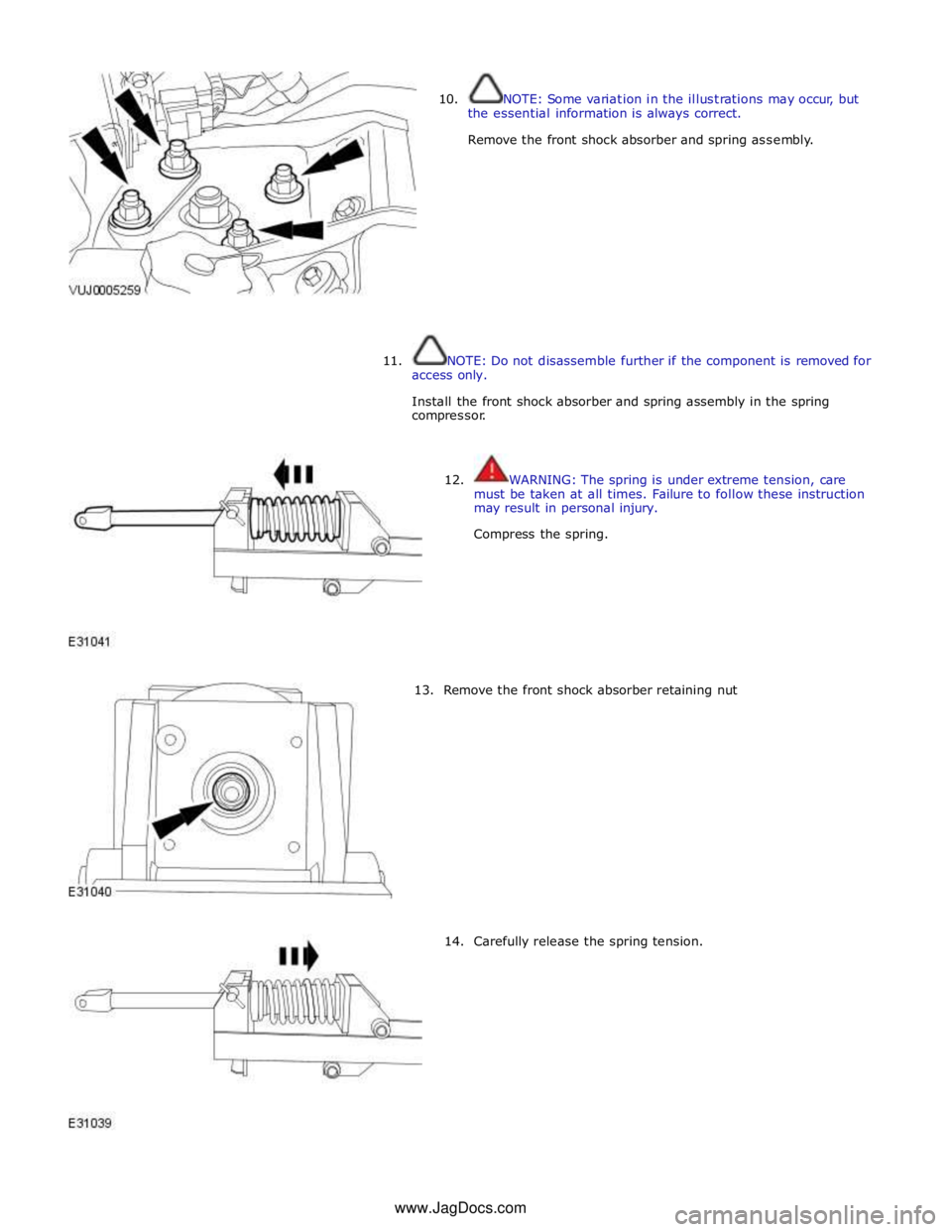
10. NOTE: Some variation in the illustrations may occur, but
the essential information is always correct.
Remove the front shock absorber and spring assembly.
11.
NOTE: Do not disassemble further if the component is removed for
access only.
Install the front shock absorber and spring assembly in the spring
compressor.
12. WARNING: The spring is under extreme tension, care
must be taken at all times. Failure to follow these instruction
may result in personal injury.
Compress the spring.
13. Remove the front shock absorber retaining nut
14. Carefully release the spring tension. www.JagDocs.com
Page 434 of 3039

Rear Suspension - Shock Absorber and Spring Assembly
Disassembly and Assembly Published: 11-May-2011
Disassembly
1. Remove the shock absorber and spring assembly.
For additional information, refer to Shock Absorber and Spring Assembly in this section.
2. WARNING: Make sure the shock absorber is secured by fully
inserting the locking pin in to the special tool. Failure to
follow these instructions may result in personal injury.
Install the shock absorber and spring assembly to the special
tool as shown.
3. WARNING: AS THE SPRING IS UNDER EXTREME TENSION
CARE MUST BE TAKEN AT ALL TIMES. FAILURE TO FOLLOW
THESE INSTRUCTIONS MAY RESULT IN PERSONAL INJURY.
Clamp the road spring.
4. Remove the shock absorber retaining nut.
Remove and discard the retaining nut. Compressor, Coil Spring
204-476 Special Tool(s) www.JagDocs.com
Page 845 of 3039

Item Specification Camshaft journal maximum run out limit (mm) Camshaft journals to end journals 0.03 Camshaft journals to adjacent journals 0.015 Camshaft journal maximum out of round (mm) - all journals 0.005 Torque Specification
NOTE: A = Refer to procedure for correct torque sequence.
Description Nm lb-ft lb-in Engine cover mounting bolts 10 7 - Accessory drive belt tensioner retaining bolt 40 30 - Supercharger belt idler/tensioner bracket retaining bolts 25 18 - Secondary drive belt idler retaining bolts 40 30 - Power steering pump pulley retaining bolts 25 18 - Power steering pump retaining bolts 25 18 - Power steering pump bracket to engine retaining bolts 25 18 - Generator retaining bolts 48 35 - Starter motor retaining bolts 48 35 - Air conditioning compressor retaining bolts 25 18 - Engine mounting to engine mounting bracket retaining nuts 48 35 - Engine mounting to subframe retaining nuts 63 46 - Engine mounting bracket to engine retaining bolts 48 35 - Crankshaft damper pulley retaining LH threaded bolt 200 + 270° 148 + 180° - Flexplate retaining bolts 45 + 90° 33 + 90° - Exhaust manifold heat shield retaining bolts A - - Exhaust manifold retaining bolts A - - Engine wiring harness bracket retaining bolts 10 7 - Coolant outlet pipe 10 7 - Intercooler retaining bolts 25 18 - Intake manifold retaining bolts 25 18 - Oil Cooler retaining bolts 13 10 - Knock sensor (KS) retaining bolt 20 14 - Ignition coil retaining bolts 8 - 71 Spark plugs 20 15 - Fuel rail retaining bolts A - - High pressure fuel pipe retaining bolts A - - High pressure fuel pump retaining bolts 12 9 - Oil filter housing assembly retaining bolts 12 9 - Oil filter cap 28 21 - Lifting eye bolts 25 + 90° 18 + 90° - Manifold absolute pressure and temperature (MAPT) sensor sensor retaining bolts 5 - 44 Coolant pump retaining bolts 12 9 - Variable valve timing (VVT) oil control solenoid retaining bolts 10 7 - Camshaft position (CMP) sensor retaining bolts 10 7 - Camshaft cover retaining bolts 13 10 - Front upper timing cover retaining bolts 12 9 - Front lower timing cover retaining bolts A - - Engine rear cover retaining bolts A - - VVT to camshaft retaining bolts 32 24 - Camshaft bearing caps retaining bolts 11 8 - Primary timing chain fixed guide retaining bolts 12 9 - Primary timing chain tensioner retaining bolts 12 9 - Primary timing chain tensioner guide blade retaining bolts 25 18 - Auxiliary chain tensioner guide retaining bolts 21 15 - Auxiliary chain fixed guide retaining bolt 12 9 - Oil pump sprocket retaining bolt 21 15 - Cylinder head retaining bolts A - - Engine oil level (EOL) sensor retaining bolt 12 9 - Oil pan to oil sump body retaining bolts 12 9 - Oil sump body to engine retaining bolts 25 18 - Oil pan drain plug 23 17 - Oil transfer tube to Oil pan body retaining bolts 11 8 - Oil pump to engine block retaining bolts 25 18 - Pick-up pipe to oil pump retaining bolts 12 9 - Windage tray retaining bolts 25 18 - Piston cooling jet retaining bolts 12 9 - Engine block coolant draining plug 50 37 - Connecting Rod bolts Stage 1 10 7 - Stage 2 50 37 -
Page 963 of 3039

Engine - V8 S/C 5.0L Petrol - Engine Mount LH
Removal and Installation
Removal
NOTE: Removal steps in this procedure may contain installation details.
All vehicles Published: 11-May-2011
1. Refer to: Battery Disconnect and Connect (414-01 Battery, Mounting and Cables, General Procedures).
2. WARNING: Do not work on or under a vehicle supported only by a jack.
Always support the vehicle on safety stands.
Raise and support the vehicle.
3. Refer to: Air Conditioning (A/C) Compressor - V8 5.0L Petrol/V8 S/C 5.0L Petrol (412-03 Air Conditioning, Removal and Installation).
4. CAUTION: Support the engine on a jack. The angle may need to be
adjusted during this procedure.
Support the engine with the lifting equipment.
Left-hand drive vehicles
5.
6. NOTE: Note the fitted position.
Torque: 35 Nm Right-hand side shown, left-hand side similar.
Page 1247 of 3039

Published: 11-May-2011
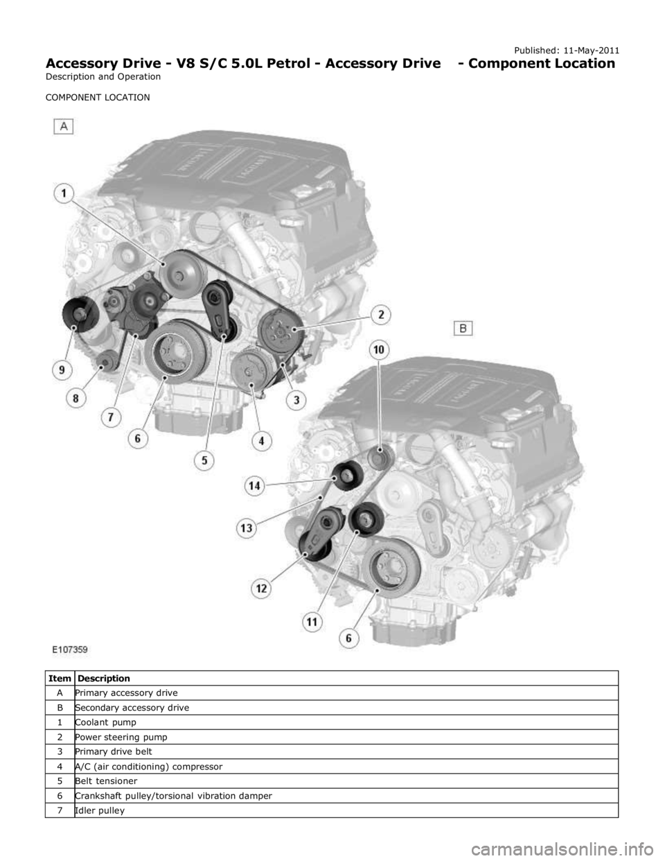
Accessory Drive - V8 S/C 5.0L Petrol - Accessory Drive - Component Location
Description and Operation
COMPONENT LOCATION
Item Description A Primary accessory drive B Secondary accessory drive 1 Coolant pump 2 Power steering pump 3 Primary drive belt 4 A/C (air conditioning) compressor 5 Belt tensioner 6 Crankshaft pulley/torsional vibration damper 7 Idler pulley