Page 1249 of 3039

Published: 11-May-2011
Accessory Drive - V8 S/C 5.0L Petrol - Accessory Drive - Overview
Description and Operation
OVERVIEW
The accessory drive is a belt system powered by a pulley attached to the front of the crankshaft. The crankshaft pulley, which
incorporates a torsional vibration damper, drives two drive belts. An automatic belt tensioner in each belt run maintains the
drive belt at the correct tension. Together with idler pulleys, the belt tensioners also guide the drive belts clear of obstructions
and set the correct 'wrap-around' of the accessory component drive pulleys to ensure a slip-free drive.
PRIMARY DRIVE BELT
The primary drive belt is a six-ribbed poly-V belt that drives the:
Coolant pump
Power steering pump
A/C (air conditioning) compressor
Generator.
SECONDARY DRIVE BELT
The secondary drive belt is an eight-ribbed poly-V belt that drives the SC (supercharger).
BELT TENSIONERS
Each belt tensioner consists of an idler pulley on the end of a spring loaded pivot arm. The pivot arms can be turned manually
for removal and installation of the drive belts.
Each belt tensioners is calibrated to automatically maintain the correct tension in the related drive belt.
Page 1663 of 3039
 refrigeran")
Climate Control System - General Information -
Lubricants, Fluids, Sealers and Adhesives
NOTE: NAS vehicles. Published: 29-Jan-2014
Description Specification Air conditioning (A/C) refrigerant R-1234yf A/C compressor oil SPA2
NOTE: ROW vehicles.
Description Specification Air conditioning (A/C) refrigerant R-134a A/C compressor oil SPA2
NOTE: EU vehicles.
Description Specification Air conditioning (A/C) refrigerant R-1234yf A/C compressor oil SPA2 Capacities
Description Grammes A/C refrigerant - all engine variants 700 Refrigerant Oil Adding Capacities
NOTE: Rotate the A/C compressor shaft at least 6 to 8 turns when draining the refrigerant oil.
Item Milliliters A/C condenser core and desiccant bag Add 25ml oil A/C evaporator Add 30ml oil A/C compressor
1. Drain old A/C compressor. With drain plug removed and ports uncapped, rotate
shaft to remove A/C compressor oil and measure the amount of oil captured. 2. Drain
new A/C compressor into a clean vessel. With drain plug removed and ports
uncapped, rotate shaft to remove oil. Then add back a quantity of the new oil that is
identical to the quantity of oil removed from the old A/C compressor. However, if this quantity is less than 30ml, then make it up to 30ml. A/C lines - if air conditioning has been operational. Add 5ml oil per A/C line A/C system after flushing - with new compressor installed No oil should be used- new oil in new compressor is sufficient A/C system after flushing - without a
new compressor installed - remaining
A/C compressor oil is to be drained.
Compressor and expansion valve must
not be flushed (removed from the circuit) Add 80ml oil A/C compressor drain plug Torque 12Nm www.JagDocs.com
Page 1664 of 3039

Published: 11-Jul-2014
Climate Control System - General Information - Climate Control System
Diagnosis and Testing
Principles of Operation
For a detailed description of the Climate Control System, refer to the relevant Description and Operation sections in the
Workshop Manual. REFER to:
Air Distribution and Filtering (412-01 Climate Control, Description and Operation), Air Distribution and Filtering (412-01 Climate Control, Description and Operation), Air Distribution and Filtering (412-01 Climate Control, Description and Operation), Heating and Ventilation (412-01 Climate Control, Description and Operation), Heating and Ventilation (412-01 Climate Control, Description and Operation), Heating and Ventilation (412-01 Climate Control, Description and Operation), Air Conditioning (412-01 Climate Control, Description and Operation), Air Conditioning (412-01 Climate Control, Description and Operation), Air Conditioning (412-01 Climate Control, Description and Operation), Control Components (412-01 Climate Control, Description and Operation), Control Components (412-01 Climate Control, Description and Operation), Control Components (412-01 Climate Control, Description and Operation), Electric Booster Heater (412-02 Auxiliary Climate Control, Description and Operation), Electric Booster Heater (412-02 Auxiliary Climate Control, Description and Operation), Electric Booster Heater (412-02 Auxiliary Climate Control, Description and Operation).
Inspection and Verification
WARNING: Servicing must be carried out by personnel familiar with both vehicle system and the charging and testing
equipment. All operations must be carried out in a well ventilated area away from open flame and heat sources.
CAUTION: Diagnosis by substitution from a donor vehicle is NOT acceptable. Substitution of control modules does not
guarantee confirmation of a fault, and may also cause additional faults in the vehicle being tested and/or the donor vehicle.
NOTE: Check and rectify basic faults before beginning diagnostic routines involving pinpoint tests.
1. Verify the customer concern
2. Visually inspect for obvious signs of damage and system integrity
Visual Inspection
Mechanical Electrical
Coolant level
Hose(s)
Coolant pump
Control flap(s)
Duct(s)
Vent(s)
Cabin air filter
Drive belt
Air conditioning compressor
Thermostatic expansion valve
Evaporator
Receiver drier
Air conditioning condenser
Refrigerant pipes Auxiliary
drive belt
Fuel fired booster heater
Fuel fired booster heater fuel pump
Fuel fired booster heater fuel pipes
Fuse(s)
Wiring harness
Electrical connectors
Blower
Air conditioning compressor
Electric cooling fan
Automatic Temperature Control Module (ATCM)
Refrigerant pressure sensor
3. If an obvious cause for an observed or reported concern is found, correct the cause (if possible) before proceeding to
the next step
4. If the cause is not visually evident, verify the symptom and refer to the Symptom Chart, alternatively check for
Diagnostic Trouble Codes (DTCs) and refer to the DTC Index
5. Check DDW for open campaigns. Refer to the corresponding bulletins and SSMs which may be valid for the specific
customer complaint and carry out the recommendations as required
Page 1668 of 3039
 System
Recovery, Evacuation and Charging
General Procedures
1. WARNING: Servicing must be carried o")
Published: 11-May-2011
Climate Control System - General Information - Air Conditioning (A/C) System
Recovery, Evacuation and Charging
General Procedures
1. WARNING: Servicing must be carried out by personnel familliar with both
vehicle system and the charging and testing equipment. All operations
must be carried out in a well ventilated area away from open flame and
heat sources.
NOTE: The receiver drier need only be changed under the following
circumstances: There is dirt in the refrigerant circuit ( eg. compressor
seizure ), the system is leaking and refrigerant has been lost to
atmosphere, or the refrigerant circuit has been open more than 24 hours,
due to repair.
Refrigerant recovery.
2. Remove the dust covers from the high and low pressure
connections.
3. Connect the high and low pressure lines to the appropriate connections.
4. Open the valves on the connections.
5. Turn the valves on the station to the correct positions.
6. Turn the process switch to the correct position.
7. Turn the main switch to 'ON'. www.JagDocs.com
Page 1676 of 3039
Published: 11-May-2011
Climate Control System - General Information - Inspection and Assembly Requirements
General Procedures
1. Check for leaks using ultraviolet (UV) Lamp.
For additional information, refer to Flourescent Dye Leak Detection in this section.
2. NOTES:
Any time a hose or component connection leak is observed, the
component and fitting must be separated, cleaned and a new O-ring
fitted and lubricated with air conditioning compressor oil.
For additional information, refer to Specifications in this section.
When separating A/C joints, cap the open connections
immediately. Do not leave open to atmosphere.
O-ring seal surfaces must be free of dirt, lint, burrs and scratches. The
O-ring and connector should be lubricated with air conditioning
compressor oil.
For additional information, refer to Specifications in this section.
Page 1678 of 3039

Published: 11-May-2011
Climate Control System - General Information - Refrigerant Oil Adding TDV6 3.0L Diesel /V8 5.0L Petrol/V8 S/C 5.0L Petrol
General Procedures
CAUTIONS:
Collect the refrigerant oil in a clean measuring cylinder. Check
Make sure that all openings are sealed. Use new blanking caps.
Be prepared to collect escaping fluids.
NOTE: Removal steps in this procedure may contain installation details.
1. NOTES:
This step only needs to be carried out when replacing
the A/C compressor.
Some variation in the illustrations may occur, but the
essential information is always correct.
Torque: 15 Nm
2. NOTES:
This step only needs to be carried out when replacing
the A/C compressor.
Some variation in the illustrations may occur, but the
essential information is always correct.
Rotate the A/C compressor shaft at least 6 to 8 turns when
draining the refrigerant oil.
3. CAUTIONS:
The refrigerant oil top-up quantity must not exceed the refrigerant
oil fill quantity.
If other A/C components are being renewed in addition to the A/C
compressor, there is no need to top up with additional refrigerant oil,
apart from filling the compressor.
Top up with the calculated quantity of new refrigerant oil.
Refer to: Specifications (412-00, Specifications).
Page 1681 of 3039
Published: 15-Nov-2013
Climate Control System - General Information - Air Conditioning (A/C)
Compressor Commissioning
General Procedures
Activation
CAUTION: Failure to follow this instruction may result in damage to the component.
1. Set the ignition to the on position, make sure the air conditioning (A/C)
is in the off position.
2. Start the engine and allow to run for a minimum of 5 minutes.
3. Set the heater controls to 22°C, with the fan speed set to 75%.
4. Switch on the A/C system.
5. Open all air vents in the dashboard.
6. Run the A/C system for a minimum of 5 minutes, while the engine is still
at idle speed.
7. Once this is achieved the compressor is stabilized, with the oil being
distributed evenly throughout the system.
Page 1695 of 3039
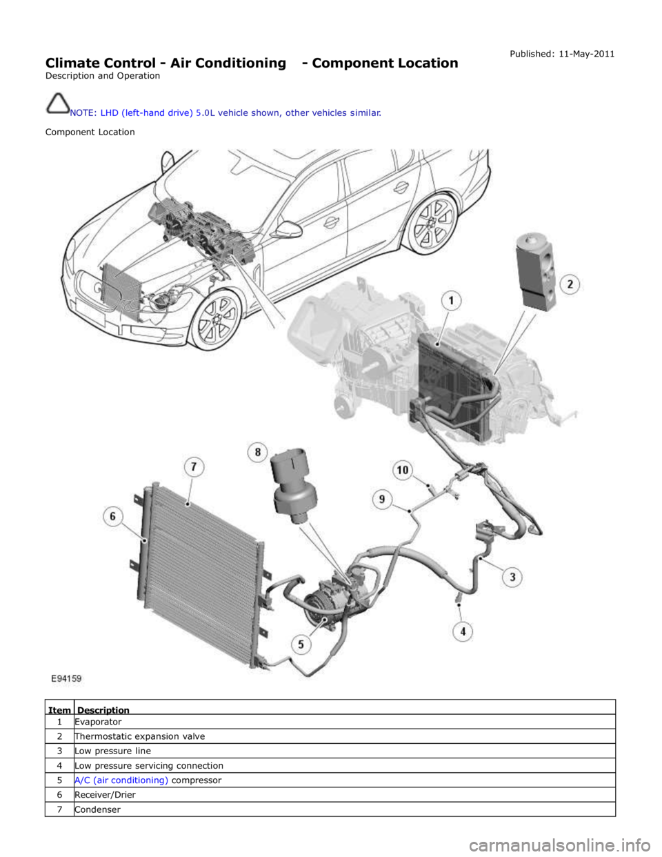
Climate Control - Air Conditioning - Component Location
Description and Operation
NOTE: LHD (left-hand drive) �� .��L vehicle shown, other vehicles sim ilar.
Component Location Published:
11-May-2011
Item Description 1 Evaporator
2 Thermostatic expansion valve
3 Low pressure line
4 Low pressure servicing connection
5
A/C (air conditioning) compressor 6 Receiver/Drier
7 Condenser
 Lamp.
For additional infor")

Compressor Commissioning
General Procedures
Activation
CAUTION: Failure to follow this instruction")