Page 1199 of 2453
EN(H6DO)(diag)-38
Inspection Mode
ENGINE (DIAGNOSTICS)
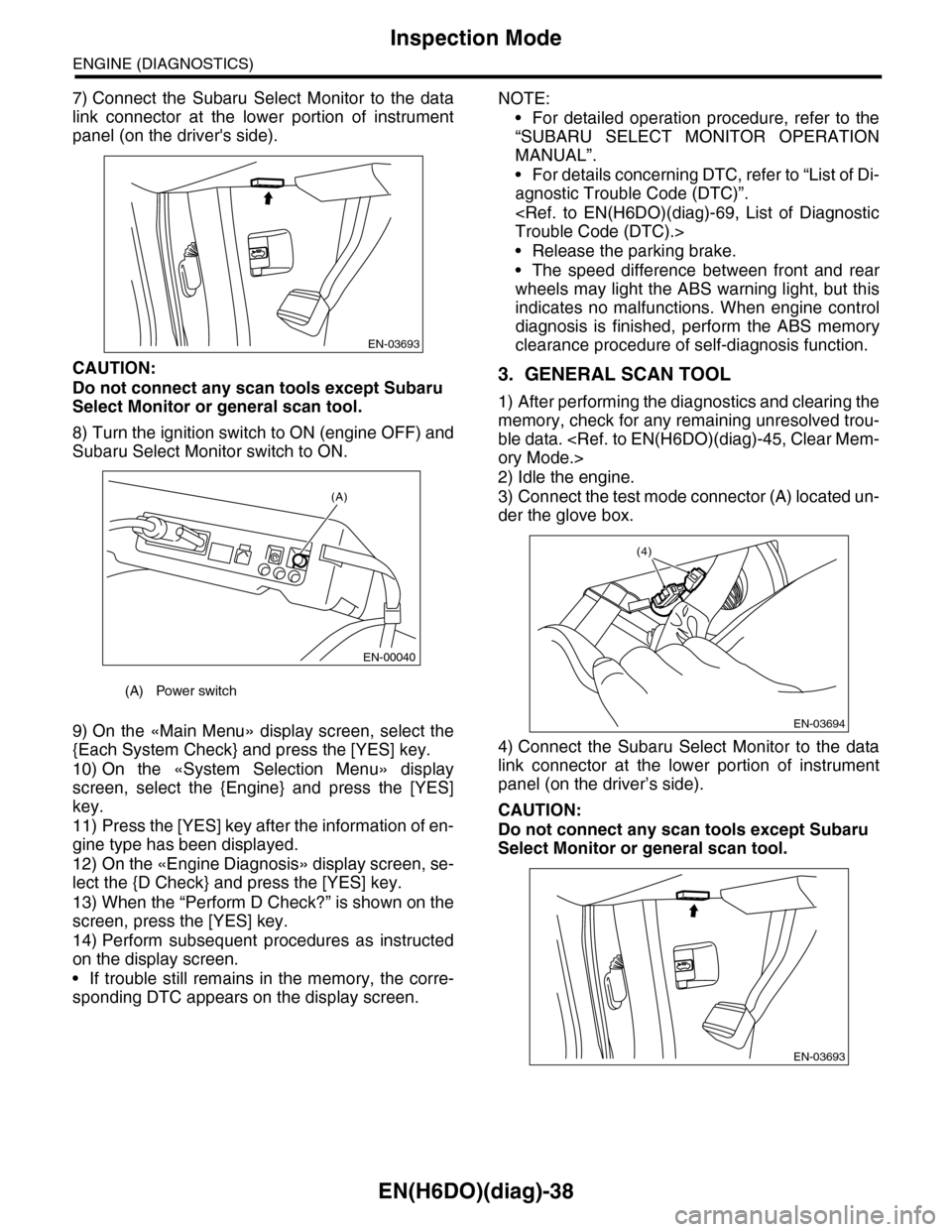
7) Connect the Subaru Select Monitor to the data
link connector at the lower portion of instrument
panel (on the driver's side).
CAUTION:
Do not connect any scan tools except Subaru
Select Monitor or general scan tool.
8) Turn the ignition switch to ON (engine OFF) and
Subaru Select Monitor switch to ON.
9) On the «Main Menu» display screen, select the
{Each System Check} and press the [YES] key.
10) On the «System Selection Menu» display
screen, select the {Engine} and press the [YES]
key.
11) Press the [YES] key after the information of en-
gine type has been displayed.
12) On the «Engine Diagnosis» display screen, se-
lect the {D Check} and press the [YES] key.
13) When the “Perform D Check?” is shown on the
screen, press the [YES] key.
14) Perform subsequent procedures as instructed
on the display screen.
•If trouble still remains in the memory, the corre-
sponding DTC appears on the display screen.
NOTE:
•For detailed operation procedure, refer to the
“SUBARU SELECT MONITOR OPERATION
MANUAL”.
•For details concerning DTC, refer to “List of Di-
agnostic Trouble Code (DTC)”.
Trouble Code (DTC).>
•Release the parking brake.
•The speed difference between front and rear
wheels may light the ABS warning light, but this
indicates no malfunctions. When engine control
diagnosis is finished, perform the ABS memory
clearance procedure of self-diagnosis function.
3. GENERAL SCAN TOOL
1) After performing the diagnostics and clearing the
memory, check for any remaining unresolved trou-
ble data.
ory Mode.>
2) Idle the engine.
3) Connect the test mode connector (A) located un-
der the glove box.
4) Connect the Subaru Select Monitor to the data
link connector at the lower portion of instrument
panel (on the driver’s side).
CAUTION:
Do not connect any scan tools except Subaru
Select Monitor or general scan tool.
(A) Power switch
EN-03693
(A)
EN-00040
EN-03694
(4)
EN-03693
Page 1201 of 2453
EN(H6DO)(diag)-40
Drive Cycle
ENGINE (DIAGNOSTICS)
12.Drive Cycle
A: PROCEDURE
For the troubleshooting, there are five driving pat-
terns of drive cycles A to E. Driving in the specified
pattern allows to diagnose malfunctioning items
listed below. After the repair of the following trouble
items, be sure to drive the vehicle with the specified
drive patterns to check whether the function is re-
sumed correctly.
1. PREPARATION FOR DRIVE CYCLE
1) Check battery voltage is more than 12 V and fuel
remains half [20 to 40 2 (5.3 to 10.6 US gal, 4.4 to
8.8 Imp gal)].
2) After performing the diagnostics and clearing the
memory, check for any remaining unresolved trou-
ble data.
ory Mode.>
3) Disconnect the test mode connectors.
NOTE:
•Perform the diagnosis after warming up the en-
gine except when the engine coolant temperature
at starting is specified.
•Perform the diagnosis twice if the DTC marked
with *. After completing the first diagnosis, stop the
engine and perform second diagnosis in same con-
dition.
Page 1207 of 2453
EN(H6DO)(diag)-46
Compulsory Valve Operation Check Mode
ENGINE (DIAGNOSTICS)
14.Compulsory Valve Operation
Check Mode
A: OPERATION
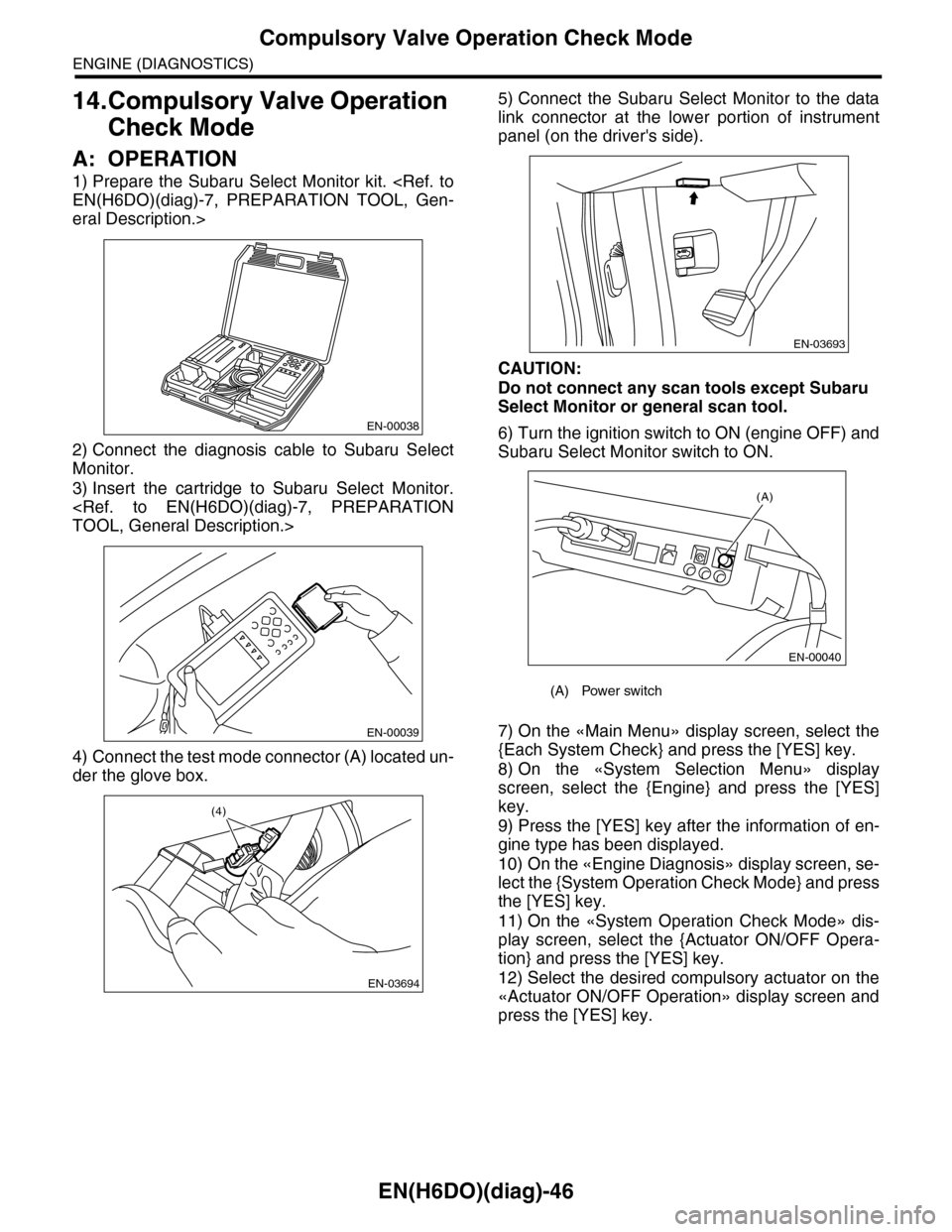
1) Prepare the Subaru Select Monitor kit.
EN(H6DO)(diag)-7, PREPARATION TOOL, Gen-
eral Description.>
2) Connect the diagnosis cable to Subaru Select
Monitor.
3) Insert the cartridge to Subaru Select Monitor.
TOOL, General Description.>
4) Connect the test mode connector (A) located un-
der the glove box.
5) Connect the Subaru Select Monitor to the data
link connector at the lower portion of instrument
panel (on the driver's side).
CAUTION:
Do not connect any scan tools except Subaru
Select Monitor or general scan tool.
6) Turn the ignition switch to ON (engine OFF) and
Subaru Select Monitor switch to ON.
7) On the «Main Menu» display screen, select the
{Each System Check} and press the [YES] key.
8) On the «System Selection Menu» display
screen, select the {Engine} and press the [YES]
key.
9) Press the [YES] key after the information of en-
gine type has been displayed.
10) On the «Engine Diagnosis» display screen, se-
lect the {System Operation Check Mode} and press
the [YES] key.
11) On the «System Operation Check Mode» dis-
play screen, select the {Actuator ON/OFF Opera-
tion} and press the [YES] key.
12) Select the desired compulsory actuator on the
«Actuator ON/OFF Operation» display screen and
press the [YES] key.
EN-00038
EN-00039
EN-03694
(4)
(A) Power switch
EN-03693
(A)
EN-00040
Page 1210 of 2453
EN(H6DO)(diag)-49
Malfunction Indicator Light
ENGINE (DIAGNOSTICS)
B: ACTIVATION OF MALFUNCTION
INDICATOR LIGHT
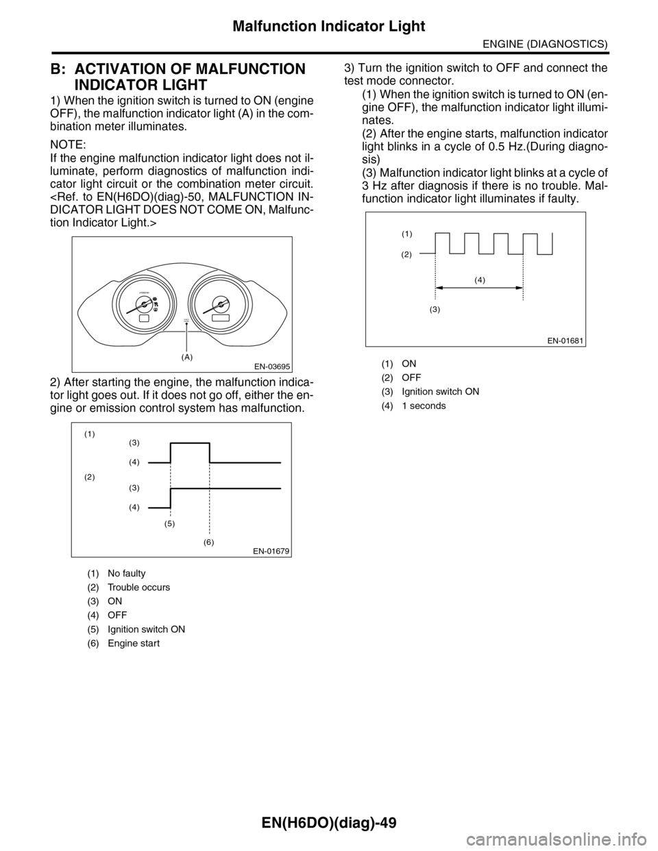
1) When the ignition switch is turned to ON (engine
OFF), the malfunction indicator light (A) in the com-
bination meter illuminates.
NOTE:
If the engine malfunction indicator light does not il-
luminate, perform diagnostics of malfunction indi-
cator light circuit or the combination meter circuit.
DICATOR LIGHT DOES NOT COME ON, Malfunc-
tion Indicator Light.>
2) After starting the engine, the malfunction indica-
tor light goes out. If it does not go off, either the en-
gine or emission control system has malfunction.
3) Turn the ignition switch to OFF and connect the
test mode connector.
(1) When the ignition switch is turned to ON (en-
gine OFF), the malfunction indicator light illumi-
nates.
(2) After the engine starts, malfunction indicator
light blinks in a cycle of 0.5 Hz.(During diagno-
sis)
(3) Malfunction indicator light blinks at a cycle of
3 Hz after diagnosis if there is no trouble. Mal-
function indicator light illuminates if faulty.
(1) No faulty
(2) Trouble occurs
(3) ON
(4) OFF
(5) Ignition switch ON
(6) Engine start
EN-03695
CHECKENGINE
(A)
x1000/min
EN-01679
(1)
(2)
(5)
(6)
(3)
(4)
(3)
(4)
(1) ON
(2) OFF
(3) Ignition switch ON
(4) 1 seconds
EN-01681
(2)
(1)
(4)
(3)
Page 1211 of 2453
EN(H6DO)(diag)-50
Malfunction Indicator Light
ENGINE (DIAGNOSTICS)
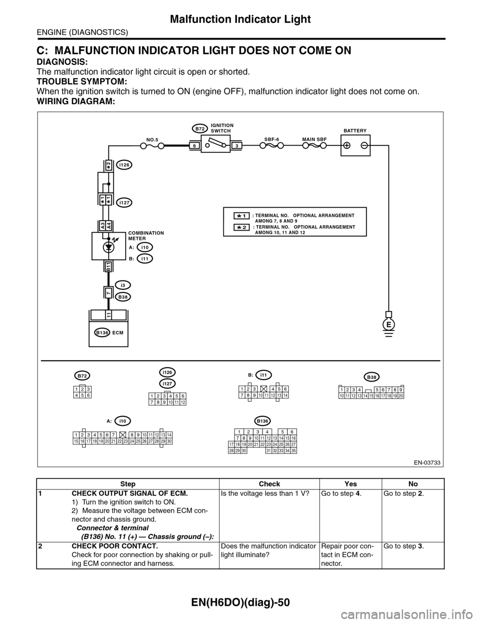
C: MALFUNCTION INDICATOR LIGHT DOES NOT COME ON
DIAGNOSIS:
The malfunction indicator light circuit is open or shorted.
TROUBLE SYMPTOM:
When the ignition switch is turned to ON (engine OFF), malfunction indicator light does not come on.
WIRING DIAGRAM:
EN-03733
3
B72
i3
B38
B136
SBF-66
11
A4
7
MAIN SBFNO.5
B11
E
A3
B72
134562
B38
1234 5678910 11 12 13 14 15 16 17 18 19 20
ECM
COMBINATIONMETER
IGNITIONSWITCHBATTERY
i126
i1271*1*
2*
i10A:
i11B:
i127
i126
123456789101112
1234567891011121314
i11B:
123456789101112131415161718192021222324252627282930
i10A:
2* : TERMINAL NO. OPTIONAL ARRANGEMENT AMONG 10, 11 AND 12
1* : TERMINAL NO. OPTIONAL ARRANGEMENT AMONG 7, 8 AND 9
B136
16101112131415252430
9871718192028212223293231
123456
2726333435
Step Check Yes No
1CHECK OUTPUT SIGNAL OF ECM.
1) Turn the ignition switch to ON.
2) Measure the voltage between ECM con-
nector and chassis ground.
Connector & terminal
(B136) No. 11 (+) — Chassis ground (–):
Is the voltage less than 1 V? Go to step 4.Go to step 2.
2CHECK POOR CONTACT.
Check for poor connection by shaking or pull-
ing ECM connector and harness.
Does the malfunction indicator
light illuminate?
Repair poor con-
tact in ECM con-
nector.
Go to step 3.
Page 1212 of 2453
EN(H6DO)(diag)-51
Malfunction Indicator Light
ENGINE (DIAGNOSTICS)
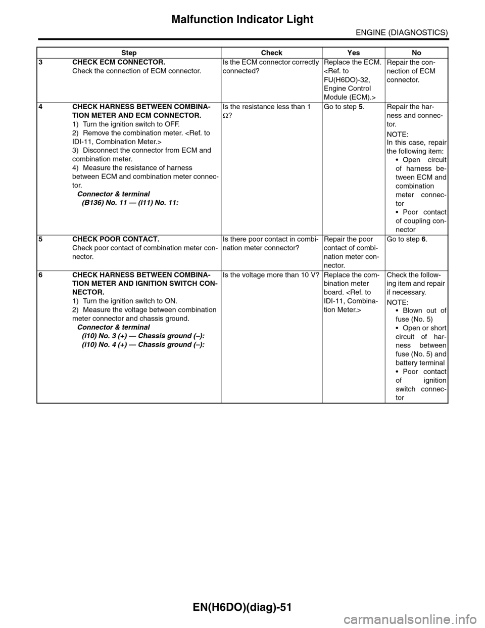
3CHECK ECM CONNECTOR.
Check the connection of ECM connector.
Is the ECM connector correctly
connected?
Replace the ECM.
FU(H6DO)-32,
Engine Control
Module (ECM).>
Repair the con-
nection of ECM
connector.
4CHECK HARNESS BETWEEN COMBINA-
TION METER AND ECM CONNECTOR.
1) Turn the ignition switch to OFF.
2) Remove the combination meter.
IDI-11, Combination Meter.>
3) Disconnect the connector from ECM and
combination meter.
4) Measure the resistance of harness
between ECM and combination meter connec-
tor.
Connector & terminal
(B136) No. 11 — (i11) No. 11:
Is the resistance less than 1
Ω?
Go to step 5.Repair the har-
ness and connec-
tor.
NOTE:In this case, repair
the following item:
•Open circuit
of harness be-
tween ECM and
combination
meter connec-
tor
•Poor contact
of coupling con-
nector
5CHECK POOR CONTACT.
Check poor contact of combination meter con-
nector.
Is there poor contact in combi-
nation meter connector?
Repair the poor
contact of combi-
nation meter con-
nector.
Go to step 6.
6CHECK HARNESS BETWEEN COMBINA-
TION METER AND IGNITION SWITCH CON-
NECTOR.
1) Turn the ignition switch to ON.
2) Measure the voltage between combination
meter connector and chassis ground.
Connector & terminal
(i10) No. 3 (+) — Chassis ground (–):
(i10) No. 4 (+) — Chassis ground (–):
Is the voltage more than 10 V? Replace the com-
bination meter
board.
IDI-11, Combina-
tion Meter.>
Check the follow-
ing item and repair
if necessary.
NOTE:
•Blown out of
fuse (No. 5)
•Open or short
circuit of har-
ness between
fuse (No. 5) and
battery terminal
•Poor contact
of ignition
switch connec-
tor
Step Check Yes No
Page 1213 of 2453
EN(H6DO)(diag)-52
Malfunction Indicator Light
ENGINE (DIAGNOSTICS)
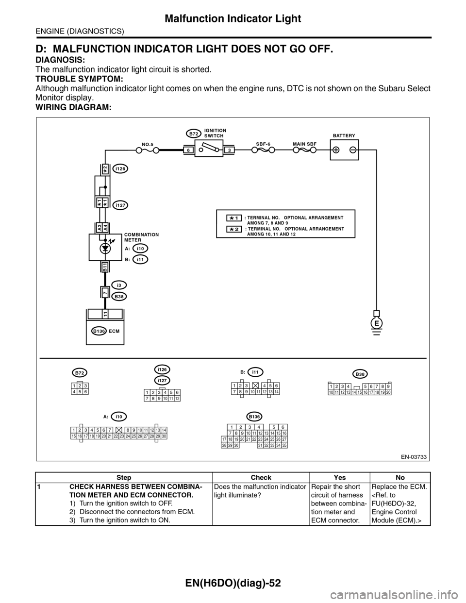
D: MALFUNCTION INDICATOR LIGHT DOES NOT GO OFF.
DIAGNOSIS:
The malfunction indicator light circuit is shorted.
TROUBLE SYMPTOM:
Although malfunction indicator light comes on when the engine runs, DTC is not shown on the Subaru Select
Monitor display.
WIRING DIAGRAM:
EN-03733
3
B72
i3
B38
B136
SBF-66
11
A4
7
MAIN SBFNO.5
B11
E
A3
B72
134562
B38
1234 5678910 11 12 13 14 15 16 17 18 19 20
ECM
COMBINATIONMETER
IGNITIONSWITCHBATTERY
i126
i1271*1*
2*
i10A:
i11B:
i127
i126
123456789101112
1234567891011121314
i11B:
123456789101112131415161718192021222324252627282930
i10A:
2* : TERMINAL NO. OPTIONAL ARRANGEMENT AMONG 10, 11 AND 12
1* : TERMINAL NO. OPTIONAL ARRANGEMENT AMONG 7, 8 AND 9
B136
16101112131415252430
9871718192028212223293231
123456
2726333435
Step Check Yes No
1CHECK HARNESS BETWEEN COMBINA-
TION METER AND ECM CONNECTOR.
1) Turn the ignition switch to OFF.
2) Disconnect the connectors from ECM.
3) Turn the ignition switch to ON.
Does the malfunction indicator
light illuminate?
Repair the short
circuit of harness
between combina-
tion meter and
ECM connector.
Replace the ECM.
FU(H6DO)-32,
Engine Control
Module (ECM).>
Page 1214 of 2453
EN(H6DO)(diag)-53
Malfunction Indicator Light
ENGINE (DIAGNOSTICS)
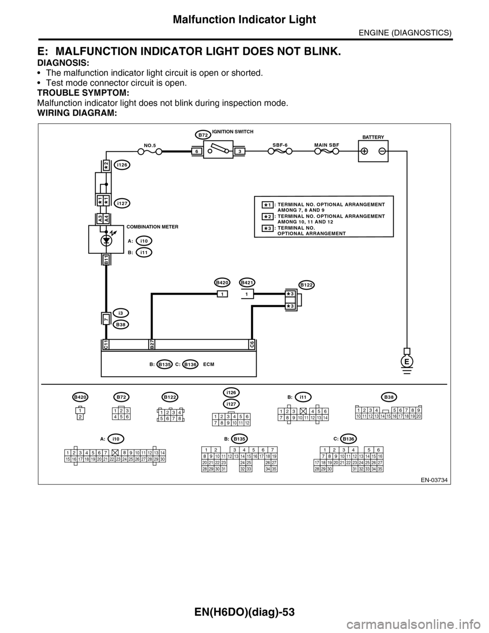
E: MALFUNCTION INDICATOR LIGHT DOES NOT BLINK.
DIAGNOSIS:
•The malfunction indicator light circuit is open or shorted.
•Test mode connector circuit is open.
TROUBLE SYMPTOM:
Malfunction indicator light does not blink during inspection mode.
WIRING DIAGRAM:
EN-03734
i126
i1271*1*
2*
i10A:
i11B:
BATTERY
3
B72
B420B421
IGNITION SWITCH
COMBINATION METER
B135B:
SBF-66
C11B27C6
ECM
B72
7
MAIN SBFNO.5
11
B420
1212
B11
i3
B38
E
A4A3
B136C:
134562
B38
1234 5678910 11 12 13 14 15 16 17 18 19 2012345678
B122
3*: TERMINAL NO. OPTIONAL ARRANGEMENT
2*: TERMINAL NO. OPTIONAL ARRANGEMENT AMONG 10, 11 AND 12
1*: TERMINAL NO. OPTIONAL ARRANGEMENT AMONG 7, 8 AND 9
B122
3*
3*
i127
i126
123456789101112
1234567891011121314
i11B:
123456789101112131415161718192021222324252627282930
i10A:B135
5672134
29
101112131415252416
30
98171819202821222332312627333435
B:B136
16101112131415252430
9871718192028212223293231
123456
2726333435
C: