2009 SUBARU TRIBECA connector
[x] Cancel search: connectorPage 1177 of 2453
EN(H6DO)(diag)-16
Engine Control Module (ECM) I/O Signal
ENGINE (DIAGNOSTICS)
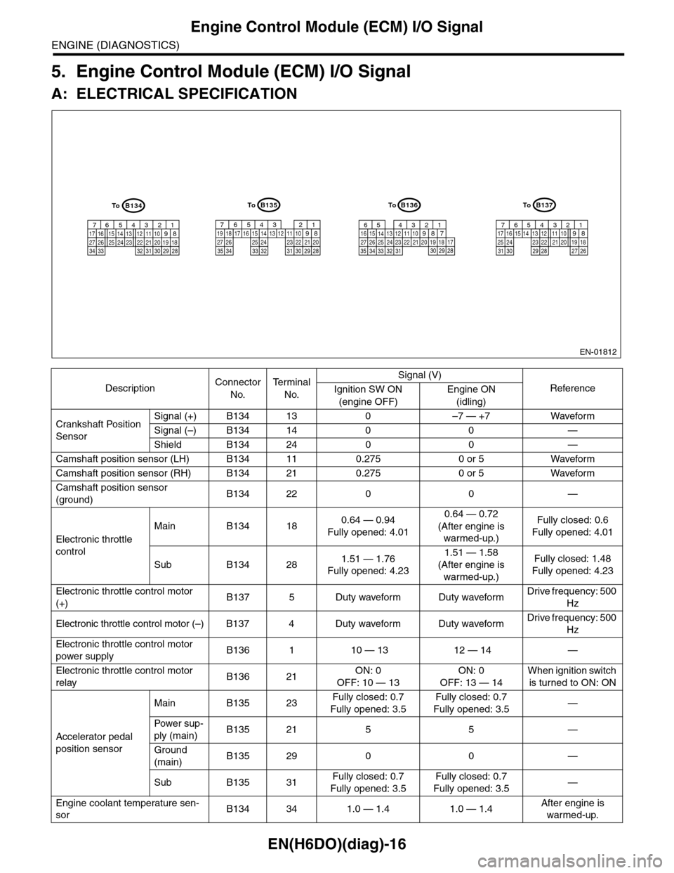
5. Engine Control Module (ECM) I/O Signal
A: ELECTRICAL SPECIFICATION
DescriptionConnector
No.
Te r m i n a l
No.
Signal (V)
ReferenceIgnition SW ON
(engine OFF)
Engine ON
(idling)
Crankshaft Position
Sensor
Signal (+) B134 13 0 –7 — +7 Waveform
Signal (–) B134 14 0 0 —
Shield B134 24 0 0 —
Camshaft position sensor (LH) B134 11 0.275 0 or 5 Waveform
Camshaft position sensor (RH) B134 21 0.275 0 or 5 Waveform
Camshaft position sensor
(ground)B134 22 0 0 —
Electronic throttle
control
Main B134 180.64 — 0.94
Fully opened: 4.01
0.64 — 0.72
(After engine is
warmed-up.)
Fully closed: 0.6
Fully opened: 4.01
Sub B134 281.51 — 1.76
Fully opened: 4.23
1.51 — 1.58
(After engine is
warmed-up.)
Fully closed: 1.48
Fully opened: 4.23
Electronic throttle control motor
(+)B137 5 Duty waveform Duty waveformDrive frequency: 500
Hz
Electronic throttle control motor (–) B137 4 Duty waveform Duty waveformDrive frequency: 500
Hz
Electronic throttle control motor
power supplyB136 1 10 — 13 12 — 14 —
Electronic throttle control motor
relayB136 21ON: 0
OFF: 10 — 13
ON: 0
OFF: 13 — 14
When ignition switch
is turned to ON: ON
Accelerator pedal
position sensor
Main B135 23Fully closed: 0.7
Fully opened: 3.5
Fully closed: 0.7
Fully opened: 3.5—
Powe r s up -
ply (main)B135 21 5 5 —
Ground
(main)B135 29 0 0 —
Sub B135 31Fully closed: 0.7
Fully opened: 3.5
Fully closed: 0.7
Fully opened: 3.5—
Engine coolant temperature sen-
sorB134 34 1.0 — 1.4 1.0 — 1.4After engine is
warmed-up.
EN-01812
B134
5678219431024 2223251112131415262728
1617181920213334 2932 3031
B136
5678219431024 2223251112131415262728
16171819202133342932303135
B135
5678219431024 2223251112131415262728
16171819202129303132333435
B137
5678219431022231112131415242526
1617181920212728293031
ToToToTo
Page 1178 of 2453
EN(H6DO)(diag)-17
Engine Control Module (ECM) I/O Signal
ENGINE (DIAGNOSTICS)
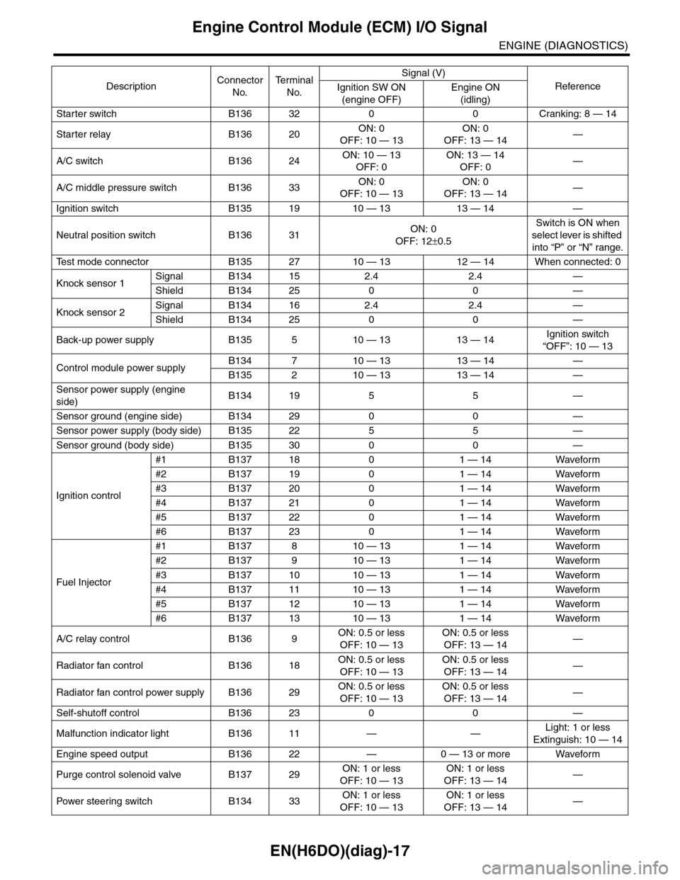
Starter switch B136 32 0 0 Cranking: 8 — 14
Starter relay B136 20ON: 0
OFF: 10 — 13
ON: 0
OFF: 13 — 14—
A/C switch B136 24ON: 10 — 13
OFF: 0
ON: 13 — 14
OFF: 0—
A/C middle pressure switch B136 33ON: 0
OFF: 10 — 13
ON: 0
OFF: 13 — 14—
Ignition switch B135 19 10 — 13 13 — 14 —
Neutral position switch B136 31ON: 0
OFF: 12±0.5
Switch is ON when
select lever is shifted
into “P” or “N” range.
Te s t m o d e c o n n e c t o r B 1 3 5 2 7 1 0 — 1 3 1 2 — 1 4 W h e n c o n n e c t e d : 0
Knock sensor 1Signal B134 15 2.4 2.4 —
Shield B134 25 0 0 —
Knock sensor 2Signal B134 16 2.4 2.4 —
Shield B134 25 0 0 —
Back-up power supply B135 5 10 — 13 13 — 14Ignition switch
“OFF”: 10 — 13
Control module power supplyB134 7 10 — 13 13 — 14 —
B135 2 10 — 13 13 — 14 —
Sensor power supply (engine
side)B134 19 5 5 —
Sensor ground (engine side) B134 29 0 0 —
Sensor power supply (body side) B135 22 5 5 —
Sensor ground (body side) B135 30 0 0 —
Ignition control
#1 B137 18 0 1 — 14 Waveform
#2 B137 19 0 1 — 14 Waveform
#3 B137 20 0 1 — 14 Waveform
#4 B137 21 0 1 — 14 Waveform
#5 B137 22 0 1 — 14 Waveform
#6 B137 23 0 1 — 14 Waveform
Fuel Injector
#1 B137 8 10 — 13 1 — 14 Waveform
#2 B137 9 10 — 13 1 — 14 Waveform
#3 B137 10 10 — 13 1 — 14 Waveform
#4 B137 11 10 — 13 1 — 14 Waveform
#5 B137 12 10 — 13 1 — 14 Waveform
#6 B137 13 10 — 13 1 — 14 Waveform
A/C relay control B136 9ON: 0.5 or less
OFF: 10 — 13
ON: 0.5 or less
OFF: 13 — 14—
Radiator fan control B136 18ON: 0.5 or less
OFF: 10 — 13
ON: 0.5 or less
OFF: 13 — 14—
Radiator fan control power supply B136 29ON: 0.5 or less
OFF: 10 — 13
ON: 0.5 or less
OFF: 13 — 14—
Self-shutoff control B136 23 0 0 —
Malfunction indicator light B136 11 — —Light: 1 or less
Extinguish: 10 — 14
Engine speed output B136 22 — 0 — 13 or more Waveform
Purge control solenoid valve B137 29ON: 1 or less
OFF: 10 — 13
ON: 1 or less
OFF: 13 — 14—
Pow er s te e r in g sw it c h B 1 3 4 33ON: 1 or less
OFF: 10 — 13
ON: 1 or less
OFF: 13 — 14—
DescriptionConnector
No.
Te r m i n a l
No.
Signal (V)
ReferenceIgnition SW ON
(engine OFF)
Engine ON
(idling)
Page 1179 of 2453
EN(H6DO)(diag)-18
Engine Control Module (ECM) I/O Signal
ENGINE (DIAGNOSTICS)
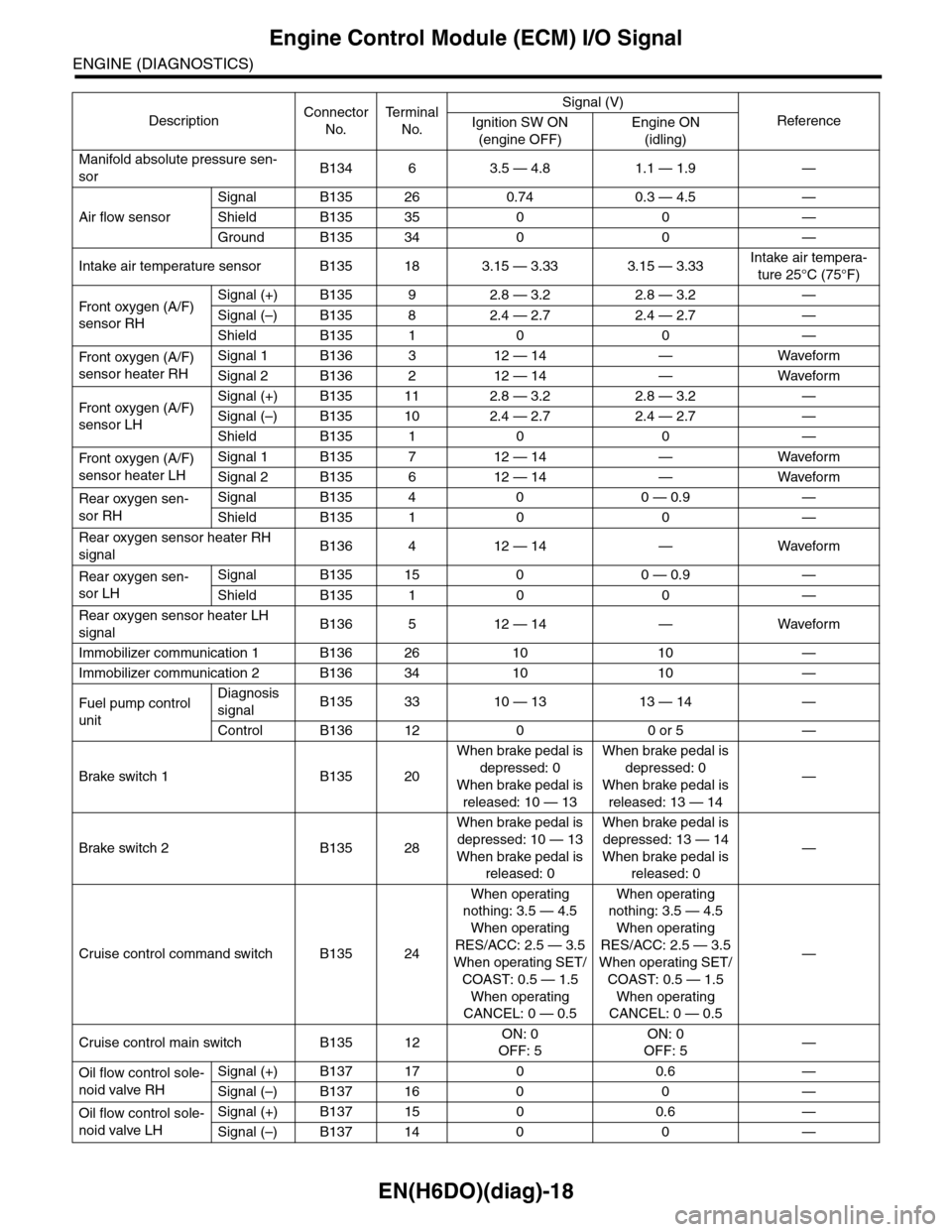
Manifold absolute pressure sen-
sorB134 6 3.5 — 4.8 1.1 — 1.9 —
Air flow sensor
Signal B135 26 0.74 0.3 — 4.5 —
Shield B135 35 0 0 —
Ground B135 34 0 0 —
Intake air temperature sensor B135 18 3.15 — 3.33 3.15 — 3.33Intake air tempera-
ture 25°C (75°F)
Fr o nt ox yg e n ( A / F)
sensor RH
Signal (+) B135 9 2.8 — 3.2 2.8 — 3.2 —
Signal (–) B135 8 2.4 — 2.7 2.4 — 2.7 —
Shield B135 1 0 0 —
Fr o nt ox yg e n ( A / F)
sensor heater RH
Signal 1 B136 3 12 — 14 — Waveform
Signal 2 B136 2 12 — 14 — Waveform
Fr o nt ox yg e n ( A / F)
sensor LH
Signal (+) B135 11 2.8 — 3.2 2.8 — 3.2 —
Signal (–) B135 10 2.4 — 2.7 2.4 — 2.7 —
Shield B135 1 0 0 —
Fr o nt ox yg e n ( A / F)
sensor heater LH
Signal 1 B135 7 12 — 14 — Waveform
Signal 2 B135 6 12 — 14 — Waveform
Rear oxygen sen-
sor RH
Signal B135 4 0 0 — 0.9 —
Shield B135 1 0 0 —
Rear oxygen sensor heater RH
signalB136 4 12 — 14 — Waveform
Rear oxygen sen-
sor LH
Signal B135 15 0 0 — 0.9 —
Shield B135 1 0 0 —
Rear oxygen sensor heater LH
signalB136 5 12 — 14 — Waveform
Immobilizer communication 1 B136 26 10 10 —
Immobilizer communication 2 B136 34 10 10 —
Fuel pump control
unit
Diagnosis
signalB135 33 10 — 13 13 — 14 —
Control B136 12 0 0 or 5 —
Brake switch 1 B135 20
When brake pedal is
depressed: 0
When brake pedal is
released: 10 — 13
When brake pedal is
depressed: 0
When brake pedal is
released: 13 — 14
—
Brake switch 2 B135 28
When brake pedal is
depressed: 10 — 13
When brake pedal is
released: 0
When brake pedal is
depressed: 13 — 14
When brake pedal is
released: 0
—
Cruise control command switch B135 24
When operating
nothing: 3.5 — 4.5
When operating
RES/ACC: 2.5 — 3.5
When operating SET/
COAST: 0.5 — 1.5
When operating
CANCEL: 0 — 0.5
When operating
nothing: 3.5 — 4.5
When operating
RES/ACC: 2.5 — 3.5
When operating SET/
COAST: 0.5 — 1.5
When operating
CANCEL: 0 — 0.5
—
Cruise control main switch B135 12ON: 0
OFF: 5
ON: 0
OFF: 5—
Oil flow control sole-
noid valve RH
Signal (+) B137 17 0 0.6 —
Signal (–) B137 16 0 0 —
Oil flow control sole-
noid valve LH
Signal (+) B137 15 0 0.6 —
Signal (–) B137 14 0 0 —
DescriptionConnector
No.
Te r m i n a l
No.
Signal (V)
ReferenceIgnition SW ON
(engine OFF)
Engine ON
(idling)
Page 1180 of 2453
EN(H6DO)(diag)-19
Engine Control Module (ECM) I/O Signal
ENGINE (DIAGNOSTICS)
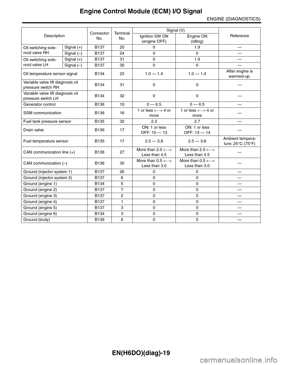
Oil switching sole-
noid valve RH
Signal (+) B137 25 0 1.9 —
Signal (–) B137 24 0 0 —
Oil switching sole-
noid valve LH
Signal (+) B137 31 0 1.9 —
Signal (–) B137 30 0 0 —
Oil temperature sensor signal B134 23 1.0 — 1.4 1.0 — 1.4After engine is
warmed-up.
Va r i a b l e va l v e l i f t d i a g n o s i s o i l
pressure switch RHB134 31 0 0 —
Va r i a b l e va l v e l i f t d i a g n o s i s o i l
pressure switch LHB134 32 0 0 —
Generator control B136 10 0 — 6.5 0 — 6.5 —
SSM communication B136 161 or less ←→ 4 or
more
1 or less ←→ 4 or
more—
Fuel tank pressure sensor B135 32 2.3 2.7 —
Drain valve B136 17ON: 1 or less
OFF: 10 — 13
ON: 1 or less
OFF: 13 — 14—
Fuel temperature sensor B135 17 2.5 — 3.8 2.5 — 3.8Ambient tempera-
ture: 25°C (75°F)
CAN communication line (+) B136 27More than 2.0 ←→
Less than 4.5
More than 2.0 ←→
Less than 4.5—
CAN communication (–) B136 35More than 0.5 ←→
Less than 3.0
More than 0.5 ←→
Less than 3.0—
Ground (injector system 1) B137 26 0 0 —
Ground (injector system 2) B137 6 0 0 —
Ground (engine 1) B134 5 0 0 —
Ground (engine 2) B137 7 0 0 —
Ground (engine 3) B137 2 0 0 —
Ground (engine 4) B137 1 0 0 —
Ground (engine 5) B137 3 0 0 —
Ground (engine 6) B134 3 0 0 —
Ground (body) B136 6 0 0 —
DescriptionConnector
No.
Te r m i n a l
No.
Signal (V)
ReferenceIgnition SW ON
(engine OFF)
Engine ON
(idling)
Page 1182 of 2453
EN(H6DO)(diag)-21
Data Link Connector
ENGINE (DIAGNOSTICS)
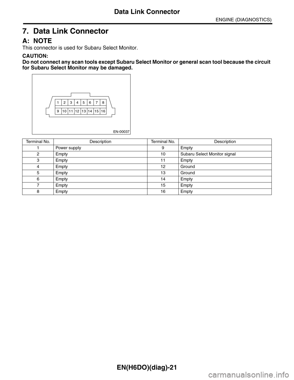
7. Data Link Connector
A: NOTE
This connector is used for Subaru Select Monitor.
CAUTION:
Do not connect any scan tools except Subaru Select Monitor or general scan tool because the circuit
for Subaru Select Monitor may be damaged.
EN-00037
12345 768
910111213 1514 16
Te r m i n a l N o . D e s c r i p t i o n Te r m i n a l N o . D e s c r i p t i o n
1Power supply 9Empty
2Empty 10Subaru Select Monitor signal
3Empty 11Empty
4Empty 12Ground
5Empty 13Ground
6Empty 14Empty
7Empty 15Empty
8Empty 16Empty
Page 1183 of 2453
EN(H6DO)(diag)-22
General Scan Tool
ENGINE (DIAGNOSTICS)
8. General Scan Tool
A: OPERATION
1. HOW TO USE GENERAL SCAN TOOL
1) Prepare a scan tool (general scan tool) required
by SAE J1978.
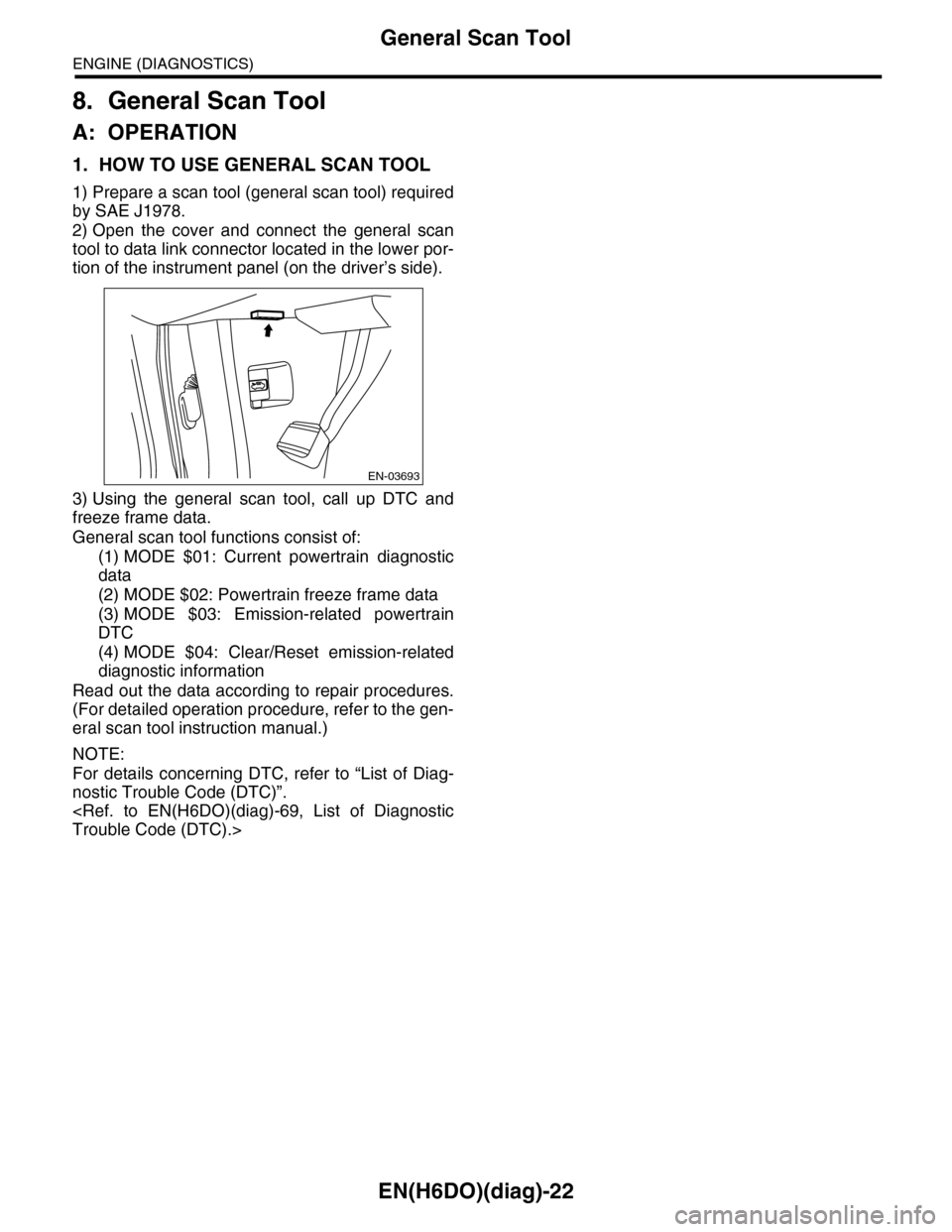
2) Open the cover and connect the general scan
tool to data link connector located in the lower por-
tion of the instrument panel (on the driver’s side).
3) Using the general scan tool, call up DTC and
freeze frame data.
General scan tool functions consist of:
(1) MODE $01: Current powertrain diagnostic
data
(2) MODE $02: Powertrain freeze frame data
(3) MODE $03: Emission-related powertrain
DTC
(4) MODE $04: Clear/Reset emission-related
diagnostic information
Read out the data according to repair procedures.
(For detailed operation procedure, refer to the gen-
eral scan tool instruction manual.)
NOTE:
For details concerning DTC, refer to “List of Diag-
nostic Trouble Code (DTC)”.
EN-03693
Page 1187 of 2453
EN(H6DO)(diag)-26
Subaru Select Monitor
ENGINE (DIAGNOSTICS)
9. Subaru Select Monitor
A: OPERATION
1. HOW TO USE SUBARU SELECT MONI-
TOR
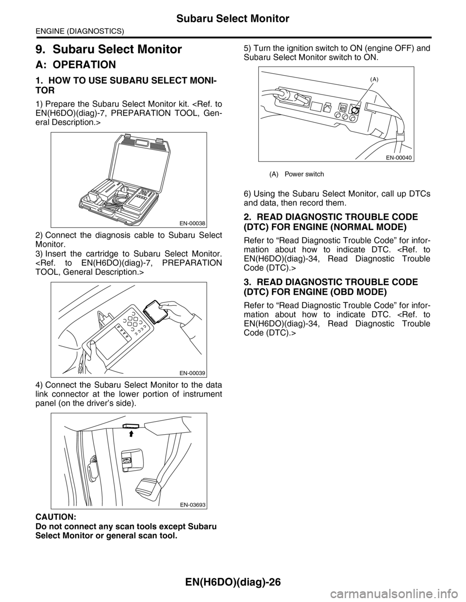
1) Prepare the Subaru Select Monitor kit.
eral Description.>
2) Connect the diagnosis cable to Subaru Select
Monitor.
3) Insert the cartridge to Subaru Select Monitor.
4) Connect the Subaru Select Monitor to the data
link connector at the lower portion of instrument
panel (on the driver’s side).
CAUTION:
Do not connect any scan tools except Subaru
Select Monitor or general scan tool.
5) Turn the ignition switch to ON (engine OFF) and
Subaru Select Monitor switch to ON.
6) Using the Subaru Select Monitor, call up DTCs
and data, then record them.
2. READ DIAGNOSTIC TROUBLE CODE
(DTC) FOR ENGINE (NORMAL MODE)
Refer to “Read Diagnostic Trouble Code” for infor-
mation about how to indicate DTC.
Code (DTC).>
3. READ DIAGNOSTIC TROUBLE CODE
(DTC) FOR ENGINE (OBD MODE)
Refer to “Read Diagnostic Trouble Code” for infor-
mation about how to indicate DTC.
Code (DTC).>
EN-00038
EN-00039
EN-03693
(A) Power switch
(A)
EN-00040
Page 1198 of 2453
EN(H6DO)(diag)-37
Inspection Mode
ENGINE (DIAGNOSTICS)
1. PREPARATION FOR THE INSPECTION
MODE
1) Check battery voltage is more than 12 V and fuel
remains half [20 to 40 2 (5.3 to 10.6 US gal, 4.4 to
8.8 Imp gal)].
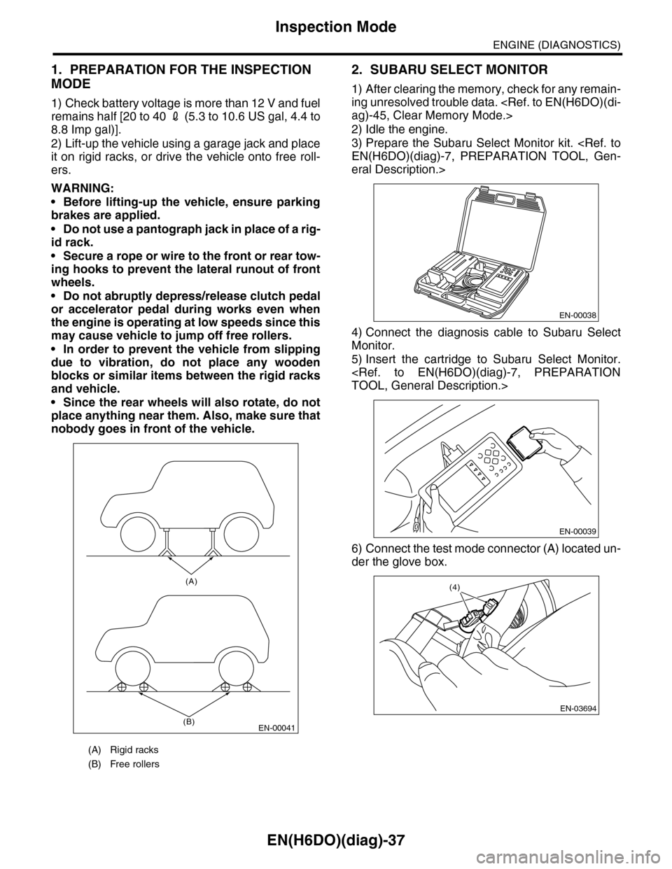
2) Lift-up the vehicle using a garage jack and place
it on rigid racks, or drive the vehicle onto free roll-
ers.
WARNING:
•Before lifting-up the vehicle, ensure parking
brakes are applied.
•Do not use a pantograph jack in place of a rig-
id rack.
•Secure a rope or wire to the front or rear tow-
ing hooks to prevent the lateral runout of front
wheels.
•Do not abruptly depress/release clutch pedal
or accelerator pedal during works even when
the engine is operating at low speeds since this
may cause vehicle to jump off free rollers.
•In order to prevent the vehicle from slipping
due to vibration, do not place any wooden
blocks or similar items between the rigid racks
and vehicle.
•Since the rear wheels will also rotate, do not
place anything near them. Also, make sure that
nobody goes in front of the vehicle.
2. SUBARU SELECT MONITOR
1) After clearing the memory, check for any remain-
ing unresolved trouble data.
2) Idle the engine.
3) Prepare the Subaru Select Monitor kit.
eral Description.>
4) Connect the diagnosis cable to Subaru Select
Monitor.
5) Insert the cartridge to Subaru Select Monitor.
6) Connect the test mode connector (A) located un-
der the glove box.
(A) Rigid racks
(B) Free rollers
EN-00041
(A)
(B)
EN-00038
EN-00039
EN-03694
(4)