2009 SUBARU TRIBECA connector
[x] Cancel search: connectorPage 1076 of 2453
VDC(diag)-84
Diagnostic Procedure with Diagnostic Trouble Code (DTC)
VEHICLE DYNAMICS CONTROL (VDC) (DIAGNOSTICS)
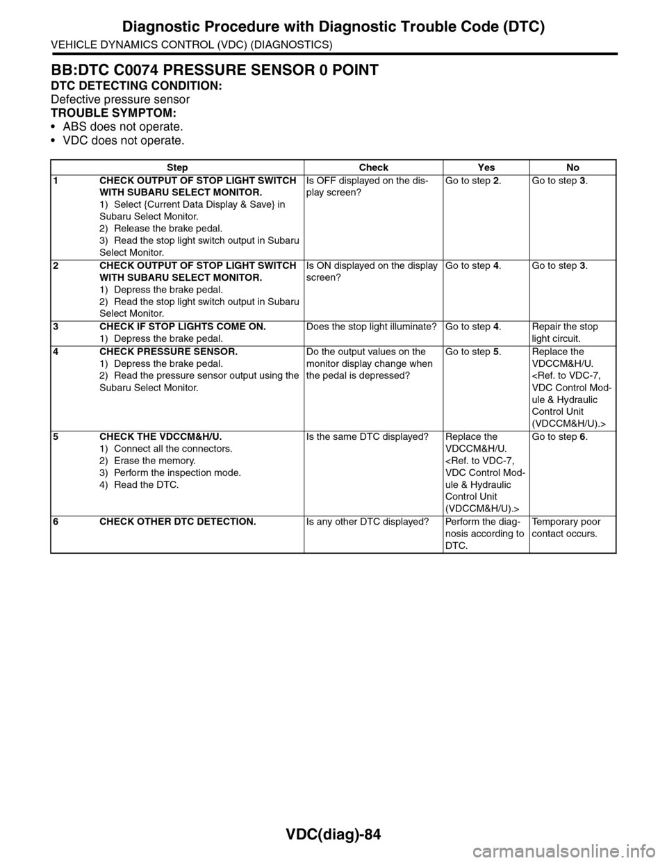
BB:DTC C0074 PRESSURE SENSOR 0 POINT
DTC DETECTING CONDITION:
Defective pressure sensor
TROUBLE SYMPTOM:
•ABS does not operate.
•VDC does not operate.
Step Check Yes No
1CHECK OUTPUT OF STOP LIGHT SWITCH
WITH SUBARU SELECT MONITOR.
1) Select {Current Data Display & Save} in
Subaru Select Monitor.
2) Release the brake pedal.
3) Read the stop light switch output in Subaru
Select Monitor.
Is OFF displayed on the dis-
play screen?
Go to step 2.Go to step 3.
2CHECK OUTPUT OF STOP LIGHT SWITCH
WITH SUBARU SELECT MONITOR.
1) Depress the brake pedal.
2) Read the stop light switch output in Subaru
Select Monitor.
Is ON displayed on the display
screen?
Go to step 4.Go to step 3.
3CHECK IF STOP LIGHTS COME ON.
1) Depress the brake pedal.
Does the stop light illuminate? Go to step 4.Repair the stop
light circuit.
4CHECK PRESSURE SENSOR.
1) Depress the brake pedal.
2) Read the pressure sensor output using the
Subaru Select Monitor.
Do the output values on the
monitor display change when
the pedal is depressed?
Go to step 5.Replace the
VDCCM&H/U.
ule & Hydraulic
Control Unit
(VDCCM&H/U).>
5CHECK THE VDCCM&H/U.
1) Connect all the connectors.
2) Erase the memory.
3) Perform the inspection mode.
4) Read the DTC.
Is the same DTC displayed? Replace the
VDCCM&H/U.
ule & Hydraulic
Control Unit
(VDCCM&H/U).>
Go to step 6.
6CHECK OTHER DTC DETECTION.Is any other DTC displayed? Perform the diag-
nosis according to
DTC.
Te m p o r a r y p o o r
contact occurs.
Page 1078 of 2453
VDC(diag)-86
Diagnostic Procedure with Diagnostic Trouble Code (DTC)
VEHICLE DYNAMICS CONTROL (VDC) (DIAGNOSTICS)
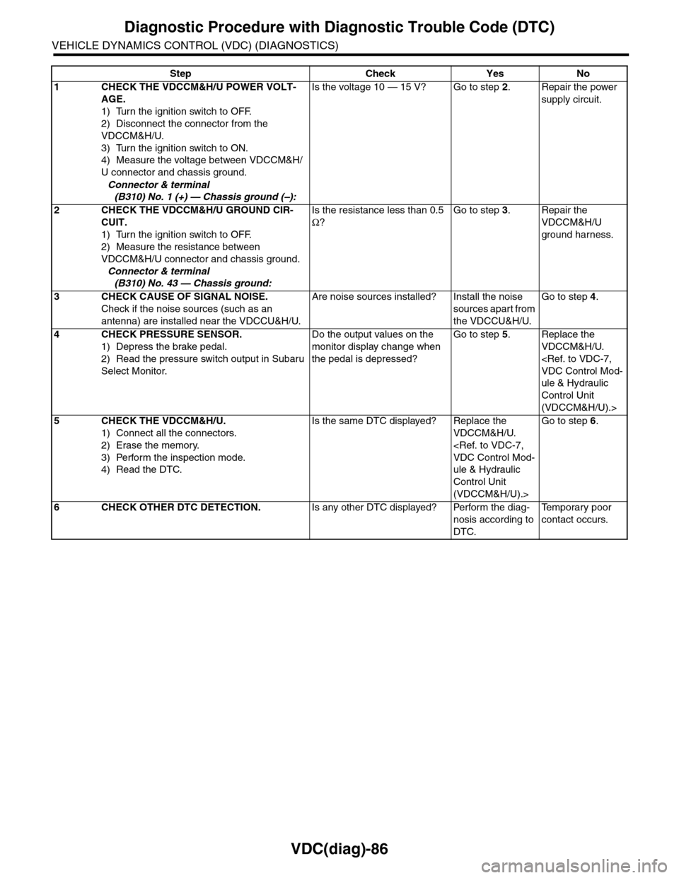
Step Check Yes No
1CHECK THE VDCCM&H/U POWER VOLT-
AGE.
1) Turn the ignition switch to OFF.
2) Disconnect the connector from the
VDCCM&H/U.
3) Turn the ignition switch to ON.
4) Measure the voltage between VDCCM&H/
U connector and chassis ground.
Connector & terminal
(B310) No. 1 (+) — Chassis ground (–):
Is the voltage 10 — 15 V? Go to step 2.Repair the power
supply circuit.
2CHECK THE VDCCM&H/U GROUND CIR-
CUIT.
1) Turn the ignition switch to OFF.
2) Measure the resistance between
VDCCM&H/U connector and chassis ground.
Connector & terminal
(B310) No. 43 — Chassis ground:
Is the resistance less than 0.5
Ω?
Go to step 3.Repair the
VDCCM&H/U
ground harness.
3CHECK CAUSE OF SIGNAL NOISE.
Check if the noise sources (such as an
antenna) are installed near the VDCCU&H/U.
Are noise sources installed? Install the noise
sources apart from
the VDCCU&H/U.
Go to step 4.
4CHECK PRESSURE SENSOR.
1) Depress the brake pedal.
2) Read the pressure switch output in Subaru
Select Monitor.
Do the output values on the
monitor display change when
the pedal is depressed?
Go to step 5.Replace the
VDCCM&H/U.
ule & Hydraulic
Control Unit
(VDCCM&H/U).>
5CHECK THE VDCCM&H/U.
1) Connect all the connectors.
2) Erase the memory.
3) Perform the inspection mode.
4) Read the DTC.
Is the same DTC displayed? Replace the
VDCCM&H/U.
ule & Hydraulic
Control Unit
(VDCCM&H/U).>
Go to step 6.
6CHECK OTHER DTC DETECTION.Is any other DTC displayed? Perform the diag-
nosis according to
DTC.
Te m p o r a r y p o o r
contact occurs.
Page 1086 of 2453
VDC-5
General Description
VEHICLE DYNAMICS CONTROL (VDC)
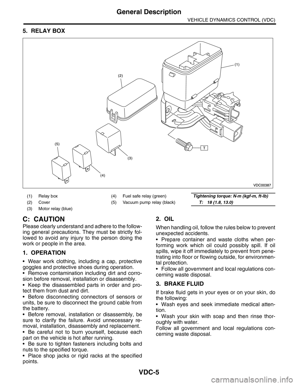
5. RELAY BOX
C: CAUTION
Please clearly understand and adhere to the follow-
ing general precautions. They must be strictly fol-
lowed to avoid any injury to the person doing the
work or people in the area.
1. OPERATION
•Wear work clothing, including a cap, protective
goggles and protective shoes during operation.
•Remove contamination including dirt and corro-
sion before removal, installation or disassembly.
•Keep the disassembled parts in order and pro-
tect them from dust and dirt.
•Before disconnecting connectors of sensors or
units, be sure to disconnect the ground cable from
the battery.
•Before removal, installation or disassembly, be
sure to clarify the failure. Avoid unnecessary re-
moval, installation, disassembly and replacement.
•Be careful not to burn yourself, because each
part on the vehicle is hot after running.
•Be sure to tighten fasteners including bolts and
nuts to the specified torque.
•Place shop jacks or rigid racks at the specified
points.
2. OIL
When handling oil, follow the rules below to prevent
unexpected accidents.
•Prepare container and waste cloths when per-
forming work which oil could possibly spill. If oil
spills, wipe it off immediately to prevent from pene-
trating into floor or flowing outside, for environmen-
tal protection.
•Follow all government and local regulations con-
cerning waste disposal.
3. BRAKE FLUID
If brake fluid gets in your eyes or on your skin, do
the following:
•Wash eyes and seek immediate medical atten-
tion.
•Wash your skin with soap and then rinse thor-
oughly with water.
Follow all government and local regulations con-
cerning waste disposal.
(1) Relay box (4) Fuel safe relay (green)Tightening torque: N·m (kgf-m, ft-lb)
(2) Cover (5) Vacuum pump relay (black)T: 18 (1.8, 13.0)
(3) Motor relay (blue)
Page 1088 of 2453
VDC-7
VDC Control Module & Hydraulic Control Unit (VDCCM&H/U)
VEHICLE DYNAMICS CONTROL (VDC)
2. VDC Control Module & Hy-
draulic Control Unit (VDC-
CM&H/U)
A: REMOVAL
1) Disconnect the ground cable from the battery.
2) Use compressed air to remove moisture and
dust around the VDCCM&H/U.
NOTE:
If the terminals become dirty, it may cause improp-
er contact.
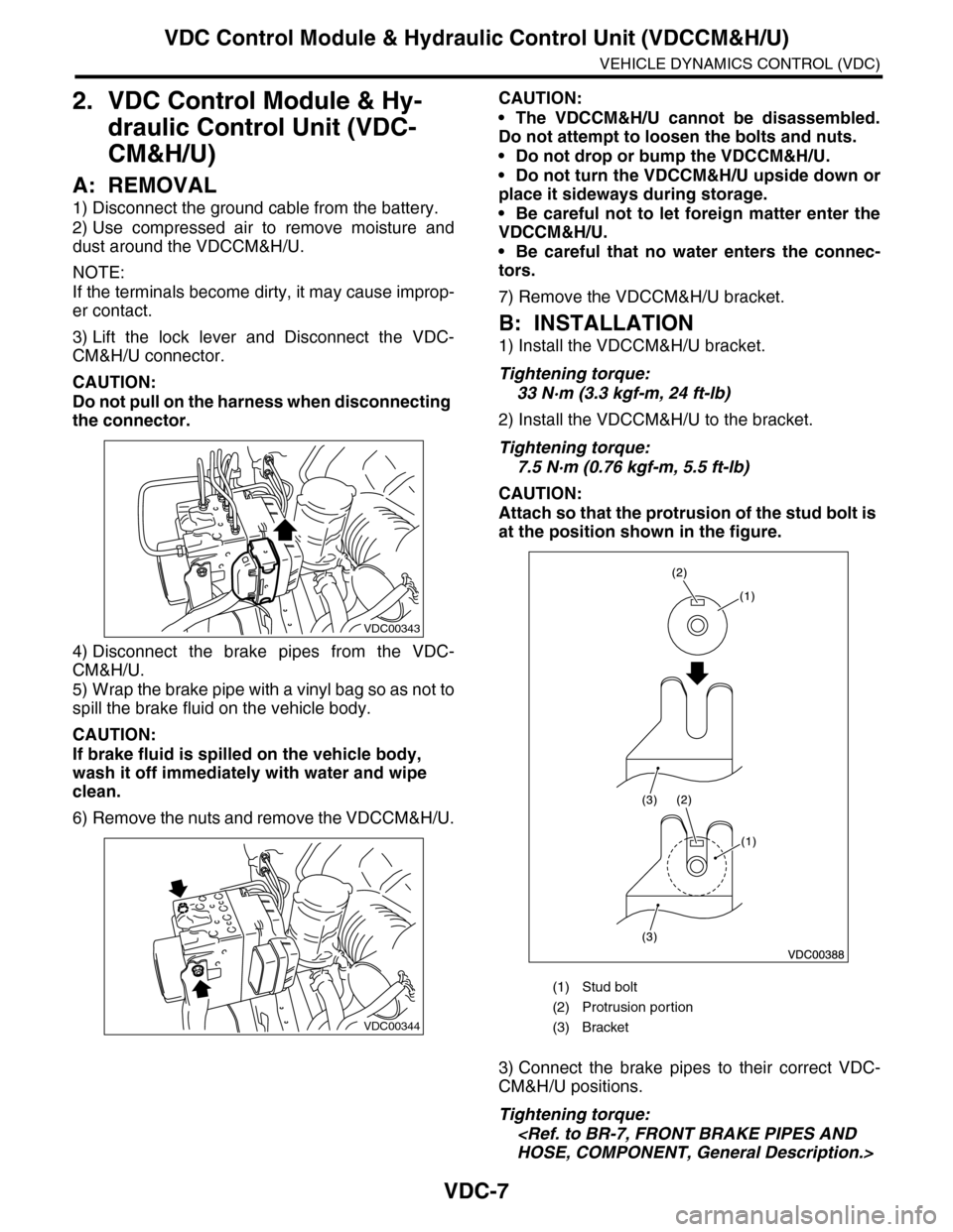
3) Lift the lock lever and Disconnect the VDC-
CM&H/U connector.
CAUTION:
Do not pull on the harness when disconnecting
the connector.
4) Disconnect the brake pipes from the VDC-
CM&H/U.
5) Wrap the brake pipe with a vinyl bag so as not to
spill the brake fluid on the vehicle body.
CAUTION:
If brake fluid is spilled on the vehicle body,
wash it off immediately with water and wipe
clean.
6) Remove the nuts and remove the VDCCM&H/U.
CAUTION:
•The VDCCM&H/U cannot be disassembled.
Do not attempt to loosen the bolts and nuts.
•Do not drop or bump the VDCCM&H/U.
•Do not turn the VDCCM&H/U upside down or
place it sideways during storage.
•Be careful not to let foreign matter enter the
VDCCM&H/U.
•Be careful that no water enters the connec-
tors.
7) Remove the VDCCM&H/U bracket.
B: INSTALLATION
1) Install the VDCCM&H/U bracket.
Tightening torque:
33 N·m (3.3 kgf-m, 24 ft-lb)
2) Install the VDCCM&H/U to the bracket.
Tightening torque:
7.5 N·m (0.76 kgf-m, 5.5 ft-lb)
CAUTION:
Attach so that the protrusion of the stud bolt is
at the position shown in the figure.
3) Connect the brake pipes to their correct VDC-
CM&H/U positions.
Tightening torque:
VDC00343
VDC00344
(1) Stud bolt
(2) Protrusion por tion
(3) Bracket
Page 1089 of 2453
VDC-8
VDC Control Module & Hydraulic Control Unit (VDCCM&H/U)
VEHICLE DYNAMICS CONTROL (VDC)
4) Connect the VDCCM&H/U connectors.
NOTE:
•Be sure to remove all foreign matter from inside
the connector before connecting.
•Make sure the VDCCM&H/U connector is se-
curely locked.
5) Bleed air from the brake system.
C: INSPECTION
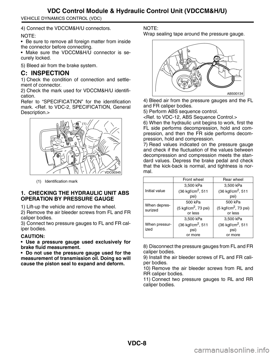
1) Check the condition of connection and settle-
ment of connector.
2) Check the mark used for VDCCM&H/U identifi-
cation.
Refer to “SPECIFICATION” for the identification
mark.
1. CHECKING THE HYDRAULIC UNIT ABS
OPERATION BY PRESSURE GAUGE
1) Lift-up the vehicle and remove the wheel.
2) Remove the air bleeder screws from FL and FR
caliper bodies.
3) Connect two pressure gauges to FL and FR cal-
iper bodies.
CAUTION:
•Use a pressure gauge used exclusively for
brake fluid measurement.
•Do not use the pressure gauge used for the
measurement of transmission oil. Doing so will
cause the piston seal to expand and deform.
NOTE:
Wrap sealing tape around the pressure gauge.
4) Bleed air from the pressure gauges and the FL
and FR caliper bodies.
5) Perform ABS sequence control.
6) When the hydraulic unit begins to work, first the
FL side performs decompression, hold and com-
pression, and then the FR side performs decom-
pression, hold and compression.
7) Read values indicated on the pressure gauge
and check if the fluctuation of the values between
decompression and compression meets the stan-
dard values. Depress the brake pedal and check
that the kick-back is normal, and tightness is nor-
mal.
8) Disconnect the pressure gauges from FL and FR
caliper bodies.
9) Install the air bleeder screws of FL and FR cali-
per bodies.
10) Remove the air bleeder screws from RL and
RR caliper bodies.
11) Connect two pressure gauges to RL and RR
caliper bodies.
(1) Identification mark
VDC00345
(1)
Front wheelRear wheel
Initial value
3,500 kPa
(36 kgf/cm2, 511
psi)
3,500 kPa
(36 kgf/cm2, 511
psi)
When depres-
surized
500 kPa
(5 kgf/cm2, 73 psi)
or less
500 kPa
(5 kgf/cm2, 73 psi)
or less
When pressur-
ized
3,500 kPa
(36 kgf/cm2, 511
psi)
or more
3,500 kPa
(36 kgf/cm2, 511
psi)
or more
ABS00134
Page 1093 of 2453
VDC-12
ABS Sequence Control
VEHICLE DYNAMICS CONTROL (VDC)
3. ABS Sequence Control
A: OPERATION
1) While the ABS sequence control is being per-
formed, the operation of the hydraulic unit can be
checked using the brake tester or pressure gauge
after the hydraulic unit solenoid valve operation.
2) ABS sequence control can be started by the
Subaru Select Monitor.
1. ABS SEQUENCE CONTROL WITH SUB-
ARU SELECT MONITOR
NOTE:
In the event of any trouble, the ABS sequence con-
trol will not operate.
1) Connect the Subaru Select Monitor to data link
connector under the driver's side instrument panel
lower cover.
2) Turn the ignition switch ON.
3) Set the Subaru Select Monitor switch to ON.
4) Set the Subaru Select Monitor to “Brake Control”
mode.
5) When the “Function check sequence” is select-
ed, the “ABS sequence control” will start.
6) Execute the following operations when the mes-
sage “Press the brake pedal so that the brake ped-
al force is between 100 and 150 kgf” is displayed.
(1) [When the brake tester is used, press brake
pedal pad with a force of 1,000 N (102 kgf, 225
lb). ]
(2) When using a pressure gauge, press the
brake pedal so that the pressure gauge indi-
cates 3,500 kPa (36 kg/cm2, 511 psi).
7) “Press the “YES” key” will be displayed. Press
the [YES] key.
8) The brake system being operated is displayed
on the Subaru Select Monitor.
Page 1096 of 2453
VDC-15
VDC Sequence Control
VEHICLE DYNAMICS CONTROL (VDC)
4. VDC Sequence Control
A: OPERATION
1) While the VDC sequence control is performed,
the operation of the hydraulic unit can be checked
using the brake tester or pressure gauge after the
hydraulic unit solenoid valve is operated.
2) VDC sequence control can be started by Subaru
Select Monitor.
1. VDC SEQUENCE CONTROL WITH SUB-
ARU SELECT MONITOR
NOTE:
In the event of any trouble, sequence control will
not operate.
1) Connect the Subaru Select Monitor to data link
connector under the driver's side instrument panel
lower cover.
2) Turn the ignition switch ON.
3) Set the Subaru Select Monitor switch to ON.
4) Set the Subaru Select Monitor to “Brake Control”
mode.
5) When the “VDC Inspection Mode” is selected
from the “Function check sequence” menu, the
“VDC sequence control” will start.
6) ”Press the “YES” key” will be displayed. Press
the [YES] key.
7) Operation points will be displayed on Subaru Se-
lect Monitor.
Page 1099 of 2453
VDC-18
Yaw Rate & Lateral G Sensor
VEHICLE DYNAMICS CONTROL (VDC)
5. Yaw Rate & Lateral G Sensor
A: REMOVAL
1) Disconnect the ground cable from the battery.
2) Remove the console box.
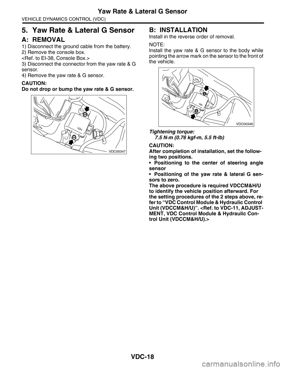
3) Disconnect the connector from the yaw rate & G
sensor.
4) Remove the yaw rate & G sensor.
CAUTION:
Do not drop or bump the yaw rate & G sensor.
B: INSTALLATION
Install in the reverse order of removal.
NOTE:
Install the yaw rate & G sensor to the body while
pointing the arrow mark on the sensor to the front of
the vehicle.
Tightening torque:
7.5 N·m (0.76 kgf-m, 5.5 ft-lb)
CAUTION:
After completion of installation, set the follow-
ing two positions.
•Positioning to the center of steering angle
sensor
•Positioning of the yaw rate & lateral G sen-
sors to zero.
The above procedure is required VDCCM&H/U
to identify the vehicle position afterward. For
the setting procedures of the 2 steps above, re-
fer to “VDC Control Module & Hydraulic Control
Unit (VDCCM&H/U)”.
trol Unit (VDCCM&H/U).>
VDC00347
VDC00346