Page 1127 of 2453

CO(H6DO)-8
Radiator Fan System
COOLING
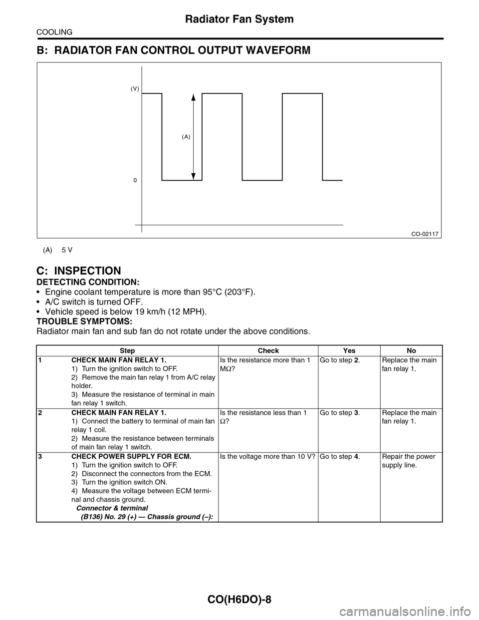
B: RADIATOR FAN CONTROL OUTPUT WAVEFORM
C: INSPECTION
DETECTING CONDITION:
•Engine coolant temperature is more than 95°C (203°F).
•A/C switch is turned OFF.
•Vehicle speed is below 19 km/h (12 MPH).
TROUBLE SYMPTOMS:
Radiator main fan and sub fan do not rotate under the above conditions.
(A) 5 V
Step Check Yes No
1CHECK MAIN FAN RELAY 1.
1) Turn the ignition switch to OFF.
2) Remove the main fan relay 1 from A/C relay
holder.
3) Measure the resistance of terminal in main
fan relay 1 switch.
Is the resistance more than 1
MΩ?
Go to step 2.Replace the main
fan relay 1.
2CHECK MAIN FAN RELAY 1.
1) Connect the battery to terminal of main fan
relay 1 coil.
2) Measure the resistance between terminals
of main fan relay 1 switch.
Is the resistance less than 1
Ω?
Go to step 3.Replace the main
fan relay 1.
3CHECK POWER SUPPLY FOR ECM.
1) Turn the ignition switch to OFF.
2) Disconnect the connectors from the ECM.
3) Turn the ignition switch ON.
4) Measure the voltage between ECM termi-
nal and chassis ground.
Connector & terminal
(B136) No. 29 (+) — Chassis ground (–):
Is the voltage more than 10 V? Go to step 4.Repair the power
supply line.
CO-02117
(V)
0
(A)
Page 1128 of 2453

CO(H6DO)-9
Radiator Fan System
COOLING
4CHECK POWER SUPPLY FOR RADIATOR
FAN CONTROL UNIT.
1) Turn the ignition switch to OFF.
2) Connect the connector to ECM.
3) Disconnect the connector from radiator fan
control unit.
4) Turn the ignition switch ON.
5) Measure the voltage between radiator fan
control unit terminal and chassis ground.
Connector & terminal
(F106) No. 3 (+) — Chassis ground (–):
Is the voltage more than 10 V? Go to step 5.Repair the power
supply line.
5CHECK HARNESS BETWEEN ECM AND RA-
DIATOR FAN CONTROL UNIT.
1) Turn the ignition switch to OFF.
2) Disconnect the connectors from the ECM.
3) Measure the resistance between radiator
fan control unit and ECM connector.
Connector & terminal
(B136) No. 18 — (F106) No. 2:
Is the resistance less than 1
Ω?
Go to step 6.Repair the open
circuit of harness
between ECM and
radiator fan con-
trol unit.
6CHECK RADIATOR FAN CONTROL UNIT
AND GROUND CIRCUIT.
1) Connect the connector to ECM and radiator
fan control unit.
2) Measure the resistance between radiator
fan control unit connector and chassis ground.
Connector & terminal
(F106) No. 1 — Chassis ground:
Is the resistance less than 5
Ω?
Go to step 7.Repair the open
circuit of harness
between radiator
fan control unit
connector and
chassis ground.
7CHECK MAIN FAN MOTOR.
1) Disconnect the connector from radiator fan
control unit.
2) Connect the battery positive (+) terminal to
terminal No. 1 of the main fan motor, and the
ground (–) terminal to terminal No. 2.
Does the main fan motor
rotate?
Go to step 8.Replace the main
fan motor.
8CHECK SUB FAN MOTOR.
1) Disconnect the connector from radiator fan
control unit.
2) Connect the battery positive (+) terminal to
terminal No. 1 of the sub fan motor, and the
ground (–) terminal to terminal No. 2.
Does the sub fan motor rotate? Go to step 9.Replace the sub
fan motor.
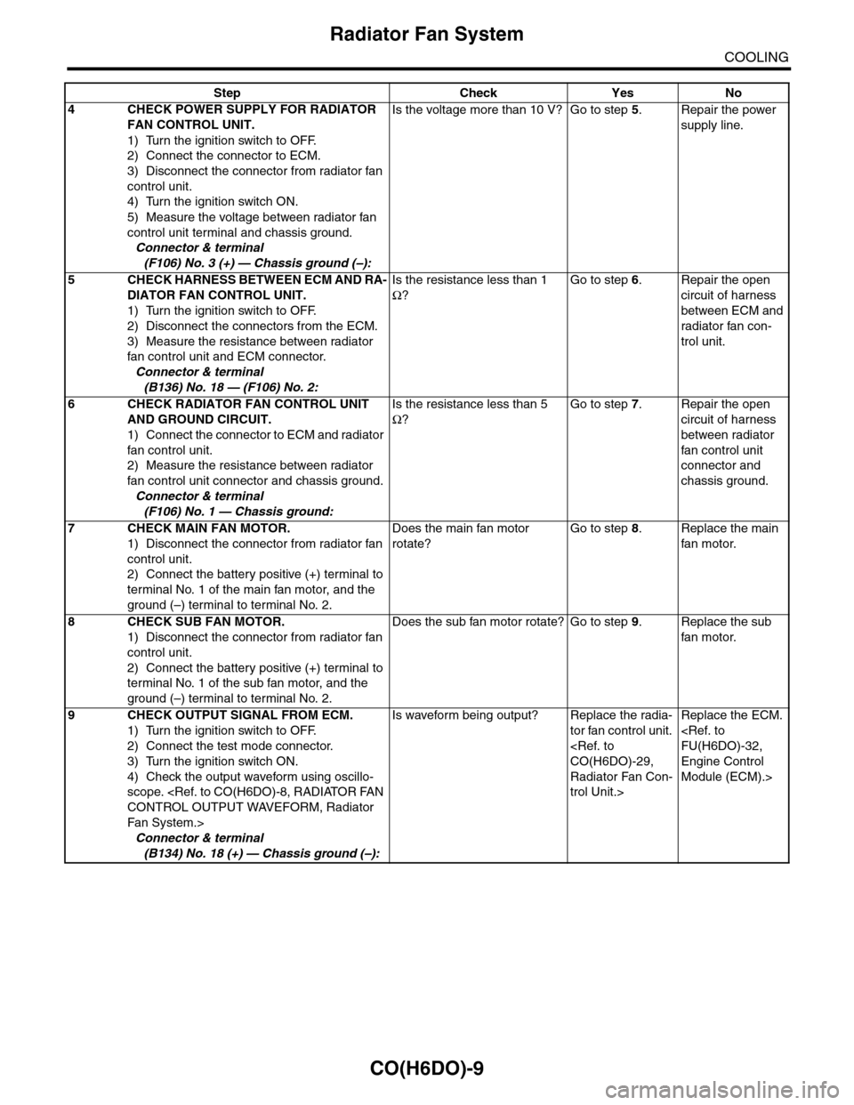
9CHECK OUTPUT SIGNAL FROM ECM.
1) Turn the ignition switch to OFF.
2) Connect the test mode connector.
3) Turn the ignition switch ON.
4) Check the output waveform using oscillo-
scope.
CONTROL OUTPUT WAVEFORM, Radiator
Fa n S y st e m. >
Connector & terminal
(B134) No. 18 (+) — Chassis ground (–):
Is waveform being output? Replace the radia-
tor fan control unit.
CO(H6DO)-29,
Radiator Fan Con-
trol Unit.>
Replace the ECM.
FU(H6DO)-32,
Engine Control
Module (ECM).>
Step Check Yes No
Page 1135 of 2453
CO(H6DO)-16
Radiator
COOLING
(5) Remove the bolts on the right side of the ra-
diator stay.
14) Disconnect the connector from radiator fan
control unit.
15) Remove the reservoir tank.
16) Disconnect the radiator hose from radiator.
17) Disconnect the ATF cooler hose from the radi-
ator.
NOTE:
Plug the ATF pipe to prevent ATF leaks.
18) Remove the front bumper.
MOVAL, Front Bumper.>
19) Remove the bolts which hold the radiator and
condenser.
20) Remove the clip holding the ambient tempera-
ture sensor harness.
21) Lift the radiator up and away from vehicle.
CO-02181
CO-02182
CO-02183
CO-02184
CO-02185
CO-02186
CO-02187
Page 1136 of 2453
CO(H6DO)-17
Radiator
COOLING
B: INSTALLATION
1) Install the radiator lower cushion to the vehicle.
2) Install the radiator to vehicle.
NOTE:
Insert the pins on the lower side of radiator into the
radiator lower cushions on the vehicle side.
3) Hold the harness of the ambient temperature
sensor with a clip.
4) Hold the radiator and condenser with bolts.
Tightening torque:
7.5 N·m (0.76 kgf-m, 5.5 ft-lb)
5) Install the front bumper.
LATION, Front Bumper.>
6) Connect the ATF cooler hoses.
7) Connect the radiator hose.
8) Install the reservoir tank.
9) Connect the connector of the radiator fan control
unit.
CO-02187
CO-02186
CO-02185
CO-02184
CO-02183
CO-02182
Page 1141 of 2453
CO(H6DO)-22
Radiator Main Fan and Fan Motor
COOLING
(5) Remove the bolts on the right side of the ra-
diator stay.
13) Disconnect the connector from radiator fan
control unit.
14) Remove the reservoir tank.
15) Remove the bolts on the upper side of the radi-
ator fan shroud.
16) Remove the radiator fan shroud.
NOTE:
When pulling the radiator fan shroud up, be careful
not to hit and damage the radiator and ATF hoses.
B: INSTALLATION
1) Tighten the bolts on the top side of the radiator
fan shroud.
Tightening torque:
7.5 N·m (0.76 kgf-m, 5.5 ft-lb)
2) Install the reservoir tank.
Tightening torque:
7.5 N·m (0.76 kgf-m, 5.5 ft-lb)
3) Connect the connector of the radiator fan control
unit.
CO-02181
CO-02182
CO-02183
CO-02189
CO-02189
CO-02183
CO-02182
Page 1143 of 2453
CO(H6DO)-24
Radiator Main Fan and Fan Motor
COOLING
9) Tighten the bolts on the lower side of the radiator
stay.
Tightening torque:
18 N·m (1.8 kgf-m, 13.3 ft-lb)
10) Tighten the bolts on the lower side of the radia-
tor fan shroud.
Tightening torque:
7.5 N·m (0.76 kgf-m, 5.5 ft-lb)
11) Install the under cover.
12) Lower the vehicle.
13) Connect the ground cable to battery.
14) Install the collector cover.
C: DISASSEMBLY
1) Disconnect the connector from radiator fan con-
trol unit.
2) Remove the radiator main fan.
3) Remove the radiator main fan motor.
D: ASSEMBLY
Assemble in the reverse order of disassembly.
Tightening torque:
3.8 N·m (0.39 kgf-m, 2.8 ft-lb)
Tightening torque:
6.3 N·m (0.64 kgf-m, 4.6 ft-lb)
(A) Connector
(B) Clip
CO-02175
CO-02188
CO-02190
(A)
(B)
CO-02199
CO-02200
CO-02200
CO-02199
Page 1144 of 2453
CO(H6DO)-25
Radiator Sub Fan and Fan Motor
COOLING
9. Radiator Sub Fan and Fan
Motor
A: REMOVAL
Refer to the radiator main fan & fan motor.
CO(H6DO)-21, REMOVAL, Radiator Main Fan and
Fan Motor.>
B: INSTALLATION
Refer to the radiator main fan & fan motor.
CO(H6DO)-22, INSTALLATION, Radiator Main
Fan and Fan Motor.>
C: DISASSEMBLY
1) Disconnect the connector from radiator fan con-
trol unit.
2) Remove the radiator sub fan.
3) Remove the radiator sub fan motor.
D: ASSEMBLY
Assemble in the reverse order of disassembly.
Tightening torque:
3.8 N·m (0.39 kgf-m, 2.8 ft-lb)
Tightening torque:
6.3 N·m (0.64 kgf-m, 4.6 ft-lb)
(A) Connector
(B) Clip
CO-02201
(A)(B)
CO-02202
CO-02203
CO-02203
CO-02202
Page 1148 of 2453
CO(H6DO)-29
Radiator Fan Control Unit
COOLING
11.Radiator Fan Control Unit
A: REMOVAL
1) Disconnect the ground cable from battery.
2) Remove the air intake duct.
7, REMOVAL, Air Intake Duct.>
3) Remove the front upper cover.
4) Remove the radiator fan control unit.
(1) Disconnect the connector from radiator fan
control unit.
(2) Remove the screws which hold the radiator
fan control unit.
B: INSTALLATION
Install in the reverse order of removal.
Tightening torque:
2.6 N·m (0.27 kgf-m, 1.9 ft-lb)
(A) Connector
(B) Screw
CO-02176
CO-02204
(A)
(B)