Page 1150 of 2453
EC(H6DO)-2
General Description
EMISSION CONTROL (AUX. EMISSION CONTROL DEVICES)
1. General Description
A: CAUTION
•Wear work clothing, including a cap, protective
goggles and protective shoes during operation.
•Remove contamination including dirt and corro-
sion before removal, installation or disassembly.
•Keep the disassembled parts in order and pro-
tect them from dust and dirt.
•Before removal, installation or disassembly, be
sure to clarify the failure. Avoid unnecessary re-
moval, installation, disassembly and replacement.
•Be careful not to burn yourself, because each
part on the vehicle is hot after running.
•Be sure to tighten fasteners including bolts and
nuts to the specified torque.
•Place shop jacks or rigid racks at the specified
points.
•Before disconnecting connectors of sensors or
units, be sure to disconnect the ground cable from
the battery.
Page 1153 of 2453
EC(H6DO)-5
Canister
EMISSION CONTROL (AUX. EMISSION CONTROL DEVICES)
4. Canister
A: REMOVAL
1) Disconnect the ground cable from battery.
2) Lift-up the vehicle.
3) Remove the clip holding the harness.
4) Remove the rear suspension assembly.
RS-16, REMOVAL, Rear Sub Frame.>
5) Disconnect the following hoses and connectors.
(1) Evaporation hose
(2) Connector
6) Remove the canister from body.
B: INSTALLATION
Install in the reverse order of removal.
Tightening torque:
8.0 N·m (0.82 kgf-m, 5.9 ft-lb)
C: INSPECTION
Make sure the canister and canister hoses are not
cracked or loose.
(A) Evaporation hose
(B) Connector
FU-02664
Page 1154 of 2453
EC(H6DO)-6
Purge Control Solenoid Valve
EMISSION CONTROL (AUX. EMISSION CONTROL DEVICES)
5. Purge Control Solenoid Valve
A: REMOVAL
1) Remove the collector cover.
2) Disconnect the ground cable from battery.
3) Remove the air intake chamber.
ber.>
4) Disconnect the connector and hoses of purge
control solenoid valve, and then remove the purge
control solenoid valve.
B: INSTALLATION
Install in the reverse order of removal.
Tightening torque:
19 N·m (1.9 kgf-m, 14.0 ft-lb)
NOTE:
Connect the evaporation hose as shown in the fig-
ure.
C: INSPECTION
Make sure the hoses are not cracked or loose.
(A) To fuel pipe (evaporation line)
(B) To intake manifold
EC-02019
EC-02019
EC-02020
(B)
(A)
Page 1158 of 2453
EC(H6DO)-10
Fuel Tank Pressure Sensor
EMISSION CONTROL (AUX. EMISSION CONTROL DEVICES)
9. Fuel Tank Pressure Sensor
A: REMOVAL
1) Set the vehicle on a lift.
2) Disconnect the ground cable from battery.
3) Open the fuel filler flap lid, and remove the fuel
filler cap.
4) Lift-up the vehicle.
5) Disconnect the connector from fuel tank pres-
sure sensor.
6) Disconnect the hose from the fuel tank pressure
sensor.
7) Remove the fuel tank pressure sensor along
with the bracket.
B: INSTALLATION
Install in the reverse order of removal.
Tightening torque:
7.4 N·m (0.75 kgf-m, 5.4 ft-lb)
C: INSPECTION
Make sure the hoses are not cracked or loose.
Page 1163 of 2453

EN(H6DO)(diag)-2
Basic Diagnostic Procedure
ENGINE (DIAGNOSTICS)
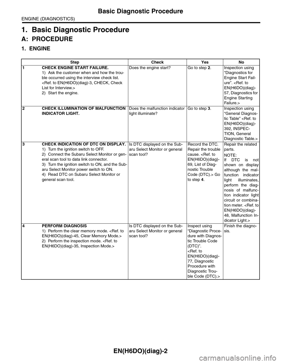
1. Basic Diagnostic Procedure
A: PROCEDURE
1. ENGINE
Step Check Yes No
1CHECK ENGINE START FAILURE.
1) Ask the customer when and how the trou-
ble occurred using the interview check list.
List for Interview.>
2) Start the engine.
Does the engine start? Go to step 2.Inspection using
“Diagnostics for
Engine Start Fail-
ure”.
EN(H6DO)(diag)-
57, Diagnostics for
Engine Starting
Fai lu r e.>
2CHECK ILLUMINATION OF MALFUNCTION
INDICATOR LIGHT.
Does the malfunction indicator
light illuminate?
Go to step 3.Inspection using
“General Diagnos-
tic Table”
EN(H6DO)(diag)-
392, INSPEC-
TION, General
Diagnostic Table.>
3CHECK INDICATION OF DTC ON DISPLAY.
1) Turn the ignition switch to OFF.
2) Connect the Subaru Select Monitor or gen-
eral scan tool to data link connector.
3) Turn the ignition switch to ON, and the Sub-
aru Select Monitor power switch to ON.
4) Read DTC on Subaru Select Monitor or
general scan tool.
Is DTC displayed on the Sub-
aru Select Monitor or general
scan tool?
Record the DTC.
Repair the trouble
cause.
EN(H6DO)(diag)-
69, List of Diag-
nostic Trouble
Code (DTC).> Go
to step 4.
Repair the related
parts.
NOTE:
If DTC is not
shown on display
although the mal-
function indicator
light illuminates,
perform the diag-
nosis of malfunc-
tion indicator light
circuit or combina-
tion meter.
EN(H6DO)(diag)-
48, Malfunction In-
dicator Light.>
4PERFORM DIAGNOSIS
1) Perform the clear memory mode.
EN(H6DO)(diag)-45, Clear Memory Mode.>
2) Perform the inspection mode.
EN(H6DO)(diag)-35, Inspection Mode.>
Is DTC displayed on the Sub-
aru Select Monitor or general
scan tool?
Inspect using
“Diagnostic Proce-
dure with Diagnos-
tic Trouble Code
(DTC)”.
EN(H6DO)(diag)-
77, Diagnostic
Procedure with
Diagnostic Trou-
ble Code (DTC).>
Finish the diagno-
sis.
Page 1165 of 2453

EN(H6DO)(diag)-4
Check List for Interview
ENGINE (DIAGNOSTICS)
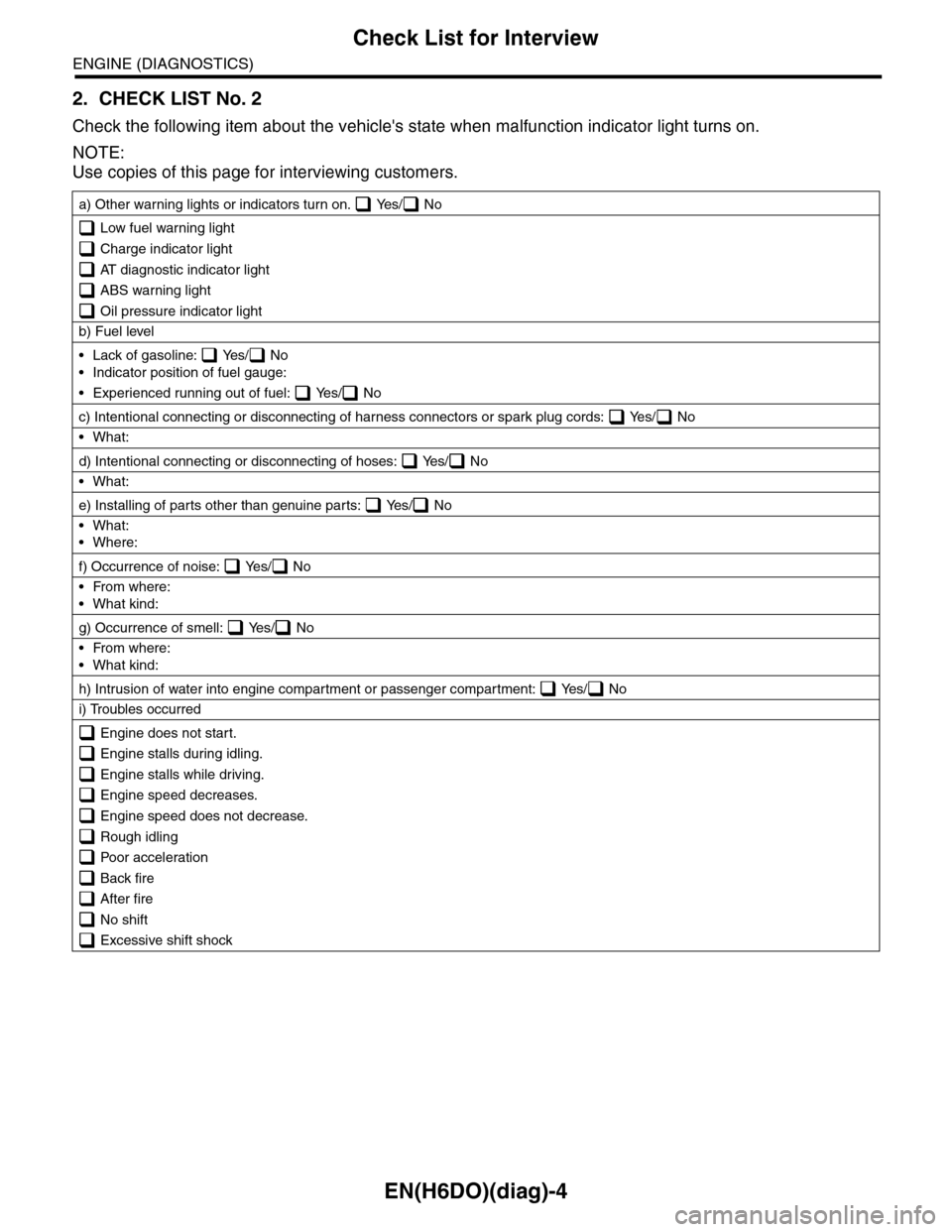
2. CHECK LIST No. 2
Check the following item about the vehicle's state when malfunction indicator light turns on.
NOTE:
Use copies of this page for interviewing customers.
a) Other warning lights or indicators turn on. Yes/ No
Low fuel warning light
Charge indicator light
AT diagnostic indicator light
ABS warning light
Oil pressure indicator light
b) Fuel level
•Lack of gasoline: Yes/ No
•Indicator position of fuel gauge:
•Experienced running out of fuel: Yes/ No
c) Intentional connecting or disconnecting of harness connectors or spark plug cords: Yes/ No
•What:
d) Intentional connecting or disconnecting of hoses: Yes/ No
•What:
e) Installing of parts other than genuine parts: Yes/ No
•What:
•Where:
f) Occurrence of noise: Yes/ No
•From where:
•What kind:
g) Occurrence of smell: Yes/ No
•From where:
•What kind:
h) Intrusion of water into engine compartment or passenger compartment: Yes/ No
i) Troubles occurred
Engine does not start.
Engine stalls during idling.
Engine stalls while driving.
Engine speed decreases.
Engine speed does not decrease.
Rough idling
Poor acceleration
Back fire
After fire
No shift
Excessive shift shock
Page 1166 of 2453

EN(H6DO)(diag)-5
General Description
ENGINE (DIAGNOSTICS)
3. General Description
A: CAUTION
1) Airbag system wiring harness is routed near the
ECM, main relay and fuel pump relay.
CAUTION:
•All airbag system wiring harnesses and con-
nectors are colored yellow. Do not use electri-
cal test equipment on these circuits.
•Be careful not to damage the airbag system
wiring harness when servicing the ECM, TCM,
main relay and fuel pump relay.
2) Never connect the battery in reverse polarity.
•The ECM will be destroyed instantly.
•The fuel injector and other parts will be dam-
aged.
3) Do not disconnect the battery terminals while the
engine is running.
A large counter electromotive force will be generat-
ed in the generator, and this voltage may damage
electronic parts such as ECM etc.
4) Before disconnecting the connectors of each
sensor and ECM, be sure to turn the ignition switch
to OFF. Perform the clear memory mode after con-
necting the connectors.
5) Poor contact has been identified as a primary
cause of this problem. Measure the voltage or re-
sistance of individual sensor or all electrical control
modules using a tapered pin with a diameter of less
than 0.64 mm (0.025 in). Do not insert the pin more
than 5 mm (0.20 in) into the part.
6) Remove the ECM from the located position after
disconnecting two cables on battery.
Otherwise, the ECM may be damaged.
CAUTION:
When replacing the ECM, be careful not to use
the wrong spec. ECM to avoid any damage on
the fuel injection system.
7) Connectors of each sensor in the engine com-
partment and the harness connectors on the en-
gine side and body side are all designed to be
waterproof. Even if the connectors are waterproof,
take care not to allow water to get into them when
washing the vehicle, or when servicing the vehicle
in rainy weather.
8) Use ECM mounting stud bolts as the grounding
point to chassis when measuring voltage and resis-
tance in the passenger compartment.
9) Use the engine ground terminal or engine as-
sembly as the grounding point to chassis when
measuring the voltage and resistance in engine
compartment.
10) Every MFI-related part is a precision part. Do
not drop them.
11) Observe the following cautions when installing
a radio in MFI equipped models.
CAUTION:
•The antenna must be kept as far apart as pos-
sible from control unit. (The ECM is located un-
der the steering column, inside of the
instrument panel lower trim panel.)
•The antenna feeder must be placed as far apart
as possible from the ECM and MFI harness.
•Carefully adjust the antenna for correct
matching.
•When mounting a large power type radio, pay
special attention to the three items mentioned
above.
•Incorrect installation of the radio may affect
the operation of ECM.
12) Release the pressure in the fuel system before
disconnecting the fuel hose. If engine starts during
this operation, run it until it stops.
13) For the model with ABS, the ABS warning light
may illuminate when performing driving test with
jacked-up or lifted-up condition, but this is not a
system malfunction. The reason for this is the
speed difference between the front and rear
wheels. After diagnosis of engine control system,
perform the ABS memory clear procedure of self-
diagnosis function.
B: INSPECTION
Before performing diagnostics, check the following
item which might affect engine problems.
1. BATTERY
1) Measure the battery voltage and specific gravity
of electrolyte.
Standard voltage: 12 V
Specific gravity: Above 1.260
2) Check the condition of the main and other fuses,
and harnesses and connectors. Also check for
proper grounding.
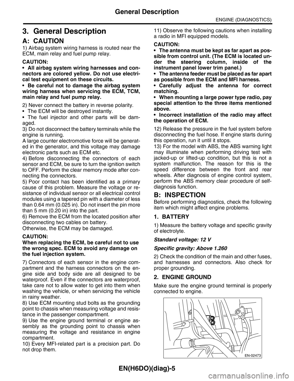
2. ENGINE GROUND
Make sure the engine ground terminal is properly
connected to engine.
EN-02473
Page 1169 of 2453
EN(H6DO)(diag)-8
Electrical Component Location
ENGINE (DIAGNOSTICS)
4. Electrical Component Location
A: LOCATION
1. ENGINE
•Control module
(1) Engine control module (ECM) (3) Test mode connector (4) Data link connector
(2) Malfunction indicator light
EN-03679
(1)
(4)
(3)
(2)
EN-03680
(1)
EN-03681
CHECKENGINE
(2)
x1000/min
EN-03682
(3)
EN-03683
(4)