2009 SUBARU TRIBECA connector
[x] Cancel search: connectorPage 1229 of 2453
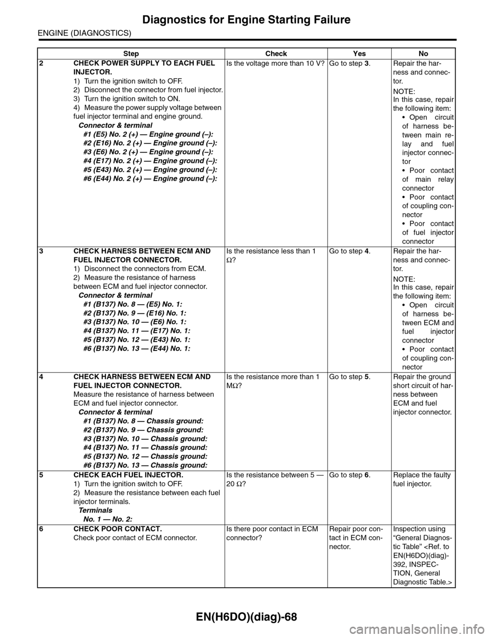
EN(H6DO)(diag)-68
Diagnostics for Engine Starting Failure
ENGINE (DIAGNOSTICS)
2CHECK POWER SUPPLY TO EACH FUEL
INJECTOR.
1) Turn the ignition switch to OFF.
2) Disconnect the connector from fuel injector.
3) Turn the ignition switch to ON.
4) Measure the power supply voltage between
fuel injector terminal and engine ground.
Connector & terminal
#1 (E5) No. 2 (+) — Engine ground (–):
#2 (E16) No. 2 (+) — Engine ground (–):
#3 (E6) No. 2 (+) — Engine ground (–):
#4 (E17) No. 2 (+) — Engine ground (–):
#5 (E43) No. 2 (+) — Engine ground (–):
#6 (E44) No. 2 (+) — Engine ground (–):
Is the voltage more than 10 V? Go to step 3.Repair the har-
ness and connec-
tor.
NOTE:In this case, repair
the following item:
•Open circuit
of harness be-
tween main re-
lay and fuel
injector connec-
tor
•Poor contact
of main relay
connector
•Poor contact
of coupling con-
nector
•Poor contact
of fuel injector
connector
3CHECK HARNESS BETWEEN ECM AND
FUEL INJECTOR CONNECTOR.
1) Disconnect the connectors from ECM.
2) Measure the resistance of harness
between ECM and fuel injector connector.
Connector & terminal
#1 (B137) No. 8 — (E5) No. 1:
#2 (B137) No. 9 — (E16) No. 1:
#3 (B137) No. 10 — (E6) No. 1:
#4 (B137) No. 11 — (E17) No. 1:
#5 (B137) No. 12 — (E43) No. 1:
#6 (B137) No. 13 — (E44) No. 1:
Is the resistance less than 1
Ω?
Go to step 4.Repair the har-
ness and connec-
tor.
NOTE:In this case, repair
the following item:
•Open circuit
of harness be-
tween ECM and
fuel injector
connector
•Poor contact
of coupling con-
nector
4CHECK HARNESS BETWEEN ECM AND
FUEL INJECTOR CONNECTOR.
Measure the resistance of harness between
ECM and fuel injector connector.
Connector & terminal
#1 (B137) No. 8 — Chassis ground:
#2 (B137) No. 9 — Chassis ground:
#3 (B137) No. 10 — Chassis ground:
#4 (B137) No. 11 — Chassis ground:
#5 (B137) No. 12 — Chassis ground:
#6 (B137) No. 13 — Chassis ground:
Is the resistance more than 1
MΩ?
Go to step 5.Repair the ground
short circuit of har-
ness between
ECM and fuel
injector connector.
5CHECK EACH FUEL INJECTOR.
1) Turn the ignition switch to OFF.
2) Measure the resistance between each fuel
injector terminals.
Te r m i n a l s
No. 1 — No. 2:
Is the resistance between 5 —
20 Ω?
Go to step 6.Replace the faulty
fuel injector.
6CHECK POOR CONTACT.
Check poor contact of ECM connector.
Is there poor contact in ECM
connector?
Repair poor con-
tact in ECM con-
nector.
Inspection using
“General Diagnos-
tic Table”
392, INSPEC-
TION, General
Diagnostic Table.>
Step Check Yes No
Page 1243 of 2453
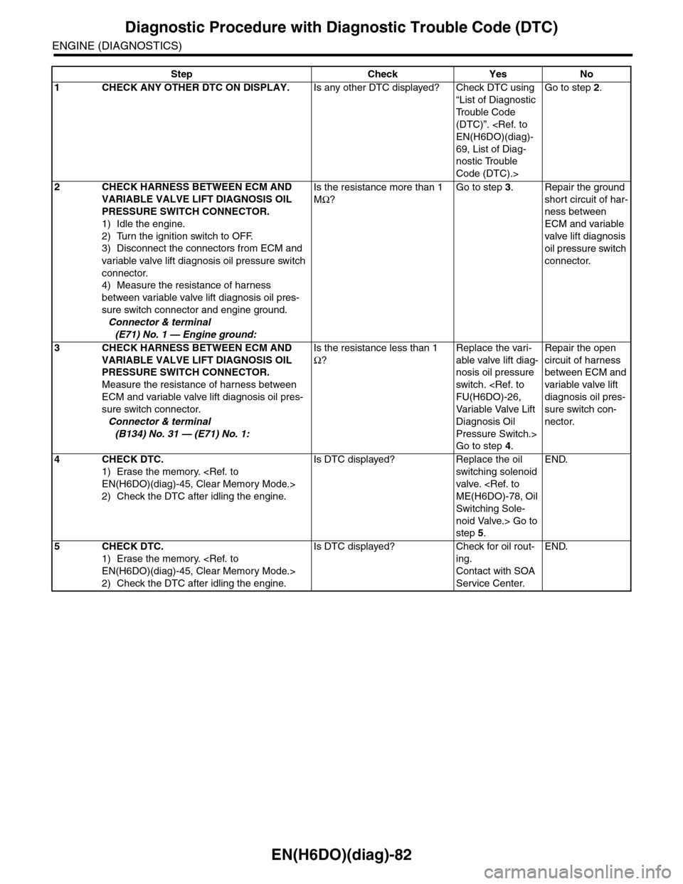
EN(H6DO)(diag)-82
Diagnostic Procedure with Diagnostic Trouble Code (DTC)
ENGINE (DIAGNOSTICS)
Step Check Yes No
1CHECK ANY OTHER DTC ON DISPLAY.Is any other DTC displayed? Check DTC using
“List of Diagnostic
Tr o u b l e C o d e
(DTC)”.
69, List of Diag-
nostic Trouble
Code (DTC).>
Go to step 2.
2CHECK HARNESS BETWEEN ECM AND
VARIABLE VALVE LIFT DIAGNOSIS OIL
PRESSURE SWITCH CONNECTOR.
1) Idle the engine.
2) Turn the ignition switch to OFF.
3) Disconnect the connectors from ECM and
variable valve lift diagnosis oil pressure switch
connector.
4) Measure the resistance of harness
between variable valve lift diagnosis oil pres-
sure switch connector and engine ground.
Connector & terminal
(E71) No. 1 — Engine ground:
Is the resistance more than 1
MΩ?
Go to step 3.Repair the ground
short circuit of har-
ness between
ECM and variable
valve lift diagnosis
oil pressure switch
connector.
3CHECK HARNESS BETWEEN ECM AND
VARIABLE VALVE LIFT DIAGNOSIS OIL
PRESSURE SWITCH CONNECTOR.
Measure the resistance of harness between
ECM and variable valve lift diagnosis oil pres-
sure switch connector.
Connector & terminal
(B134) No. 31 — (E71) No. 1:
Is the resistance less than 1
Ω?
Replace the vari-
able valve lift diag-
nosis oil pressure
switch.
Va r i a bl e Va l ve L i f t
Diagnosis Oil
Pressure Switch.>
Go to step 4.
Repair the open
circuit of harness
between ECM and
variable valve lift
diagnosis oil pres-
sure switch con-
nector.
4CHECK DTC.
1) Erase the memory.
2) Check the DTC after idling the engine.
Is DTC displayed? Replace the oil
switching solenoid
valve.
Switching Sole-
noid Valve.> Go to
step 5.
END.
5CHECK DTC.
1) Erase the memory.
2) Check the DTC after idling the engine.
Is DTC displayed? Check for oil rout-
ing.
Contact with SOA
Service Center.
END.
Page 1245 of 2453
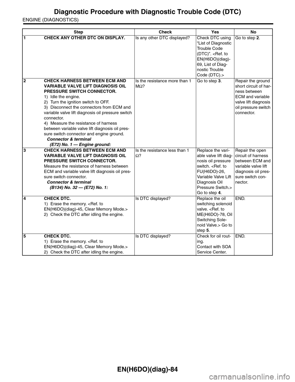
EN(H6DO)(diag)-84
Diagnostic Procedure with Diagnostic Trouble Code (DTC)
ENGINE (DIAGNOSTICS)
Step Check Yes No
1CHECK ANY OTHER DTC ON DISPLAY.Is any other DTC displayed? Check DTC using
“List of Diagnostic
Tr o u b l e C o d e
(DTC)”.
69, List of Diag-
nostic Trouble
Code (DTC).>
Go to step 2.
2CHECK HARNESS BETWEEN ECM AND
VARIABLE VALVE LIFT DIAGNOSIS OIL
PRESSURE SWITCH CONNECTOR.
1) Idle the engine.
2) Turn the ignition switch to OFF.
3) Disconnect the connectors from ECM and
variable valve lift diagnosis oil pressure switch
connector.
4) Measure the resistance of harness
between variable valve lift diagnosis oil pres-
sure switch connector and engine ground.
Connector & terminal
(E72) No. 1 — Engine ground:
Is the resistance more than 1
MΩ?
Go to step 3.Repair the ground
short circuit of har-
ness between
ECM and variable
valve lift diagnosis
oil pressure switch
connector.
3CHECK HARNESS BETWEEN ECM AND
VARIABLE VALVE LIFT DIAGNOSIS OIL
PRESSURE SWITCH CONNECTOR.
Measure the resistance of harness between
ECM and variable valve lift diagnosis oil pres-
sure switch connector.
Connector & terminal
(B134) No. 32 — (E72) No. 1:
Is the resistance less than 1
Ω?
Replace the vari-
able valve lift diag-
nosis oil pressure
switch.
Va r i a bl e Va l ve L i f t
Diagnosis Oil
Pressure Switch.>
Go to step 4.
Repair the open
circuit of harness
between ECM and
variable valve lift
diagnosis oil pres-
sure switch con-
nector.
4CHECK DTC.
1) Erase the memory.
2) Check the DTC after idling the engine.
Is DTC displayed? Replace the oil
switching solenoid
valve.
Switching Sole-
noid Valve.> Go to
step 5.
END.
5CHECK DTC.
1) Erase the memory.
2) Check the DTC after idling the engine.
Is DTC displayed? Check for oil rout-
ing.
Contact with SOA
Service Center.
END.
Page 1248 of 2453
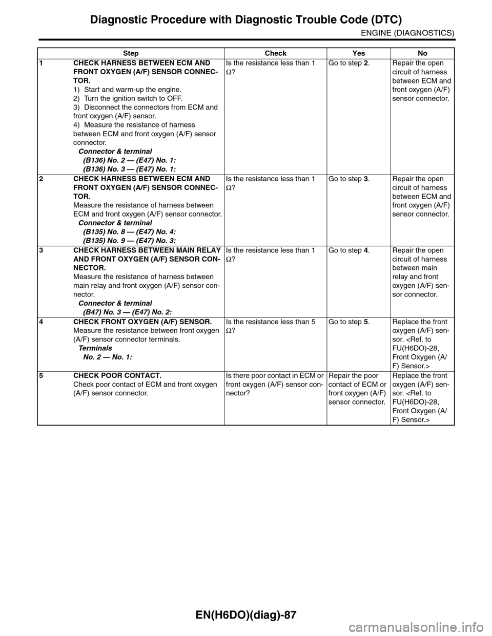
EN(H6DO)(diag)-87
Diagnostic Procedure with Diagnostic Trouble Code (DTC)
ENGINE (DIAGNOSTICS)
Step Check Yes No
1CHECK HARNESS BETWEEN ECM AND
FRONT OXYGEN (A/F) SENSOR CONNEC-
TOR.
1) Start and warm-up the engine.
2) Turn the ignition switch to OFF.
3) Disconnect the connectors from ECM and
front oxygen (A/F) sensor.
4) Measure the resistance of harness
between ECM and front oxygen (A/F) sensor
connector.
Connector & terminal
(B136) No. 2 — (E47) No. 1:
(B136) No. 3 — (E47) No. 1:
Is the resistance less than 1
Ω?
Go to step 2.Repair the open
circuit of harness
between ECM and
front oxygen (A/F)
sensor connector.
2CHECK HARNESS BETWEEN ECM AND
FRONT OXYGEN (A/F) SENSOR CONNEC-
TOR.
Measure the resistance of harness between
ECM and front oxygen (A/F) sensor connector.
Connector & terminal
(B135) No. 8 — (E47) No. 4:
(B135) No. 9 — (E47) No. 3:
Is the resistance less than 1
Ω?
Go to step 3.Repair the open
circuit of harness
between ECM and
front oxygen (A/F)
sensor connector.
3CHECK HARNESS BETWEEN MAIN RELAY
AND FRONT OXYGEN (A/F) SENSOR CON-
NECTOR.
Measure the resistance of harness between
main relay and front oxygen (A/F) sensor con-
nector.
Connector & terminal
(B47) No. 3 — (E47) No. 2:
Is the resistance less than 1
Ω?
Go to step 4.Repair the open
circuit of harness
between main
relay and front
oxygen (A/F) sen-
sor connector.
4CHECK FRONT OXYGEN (A/F) SENSOR.
Measure the resistance between front oxygen
(A/F) sensor connector terminals.
Te r m i n a l s
No. 2 — No. 1:
Is the resistance less than 5
Ω?
Go to step 5.Replace the front
oxygen (A/F) sen-
sor.
Fr o nt Ox yg en ( A /
F) Sensor.>
5CHECK POOR CONTACT.
Check poor contact of ECM and front oxygen
(A/F) sensor connector.
Is there poor contact in ECM or
front oxygen (A/F) sensor con-
nector?
Repair the poor
contact of ECM or
front oxygen (A/F)
sensor connector.
Replace the front
oxygen (A/F) sen-
sor.
Fr o nt Ox yg en ( A /
F) Sensor.>
Page 1251 of 2453
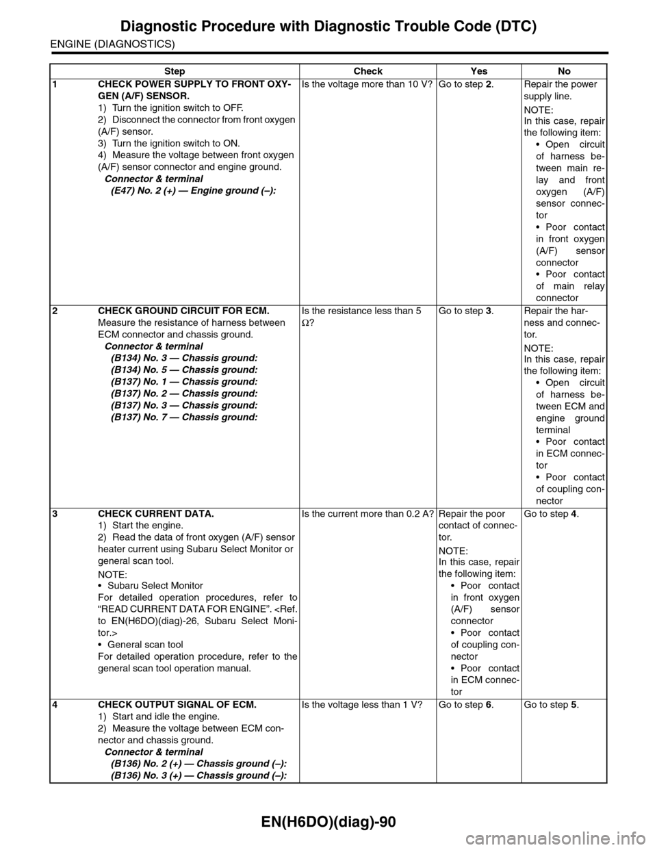
EN(H6DO)(diag)-90
Diagnostic Procedure with Diagnostic Trouble Code (DTC)
ENGINE (DIAGNOSTICS)
Step Check Yes No
1 CHECK POWER SUPPLY TO FRONT OXY-
GEN (A/F) SENSOR.
1) Turn the ignition switch to OFF.
2) Disconnect the connector from front oxygen
(A/F) sensor.
3) Turn the ignition switch to ON.
4) Measure the voltage between front oxygen
(A/F) sensor connector and engine ground.
Connector & terminal
(E47) No. 2 (+) — Engine ground (–):
Is the voltage more than 10 V? Go to step 2.Repair the power
supply line.
NOTE:
In this case, repair
the following item:
•Open circuit
of harness be-
tween main re-
lay and front
oxygen (A/F)
sensor connec-
tor
•Poor contact
in front oxygen
(A/F) sensor
connector
•Poor contact
of main relay
connector
2CHECK GROUND CIRCUIT FOR ECM.
Measure the resistance of harness between
ECM connector and chassis ground.
Connector & terminal
(B134) No. 3 — Chassis ground:
(B134) No. 5 — Chassis ground:
(B137) No. 1 — Chassis ground:
(B137) No. 2 — Chassis ground:
(B137) No. 3 — Chassis ground:
(B137) No. 7 — Chassis ground:
Is the resistance less than 5
Ω?
Go to step 3.Repair the har-
ness and connec-
tor.
NOTE:
In this case, repair
the following item:
•Open circuit
of harness be-
tween ECM and
engine ground
terminal
•Poor contact
in ECM connec-
tor
•Poor contact
of coupling con-
nector
3CHECK CURRENT DATA.
1) Start the engine.
2) Read the data of front oxygen (A/F) sensor
heater current using Subaru Select Monitor or
general scan tool.
NOTE:•Subaru Select Monitor
For detailed operation procedures, refer to
“READ CURRENT DATA FOR ENGINE”.
tor.>
•General scan tool
For detailed operation procedure, refer to the
general scan tool operation manual.
Is the current more than 0.2 A? Repair the poor
contact of connec-
tor.
NOTE:
In this case, repair
the following item:
•Poor contact
in front oxygen
(A/F) sensor
connector
•Poor contact
of coupling con-
nector
•Poor contact
in ECM connec-
tor
Go to step 4.
4CHECK OUTPUT SIGNAL OF ECM.
1) Start and idle the engine.
2) Measure the voltage between ECM con-
nector and chassis ground.
Connector & terminal
(B136) No. 2 (+) — Chassis ground (–):
(B136) No. 3 (+) — Chassis ground (–):
Is the voltage less than 1 V? Go to step 6.Go to step 5.
Page 1252 of 2453
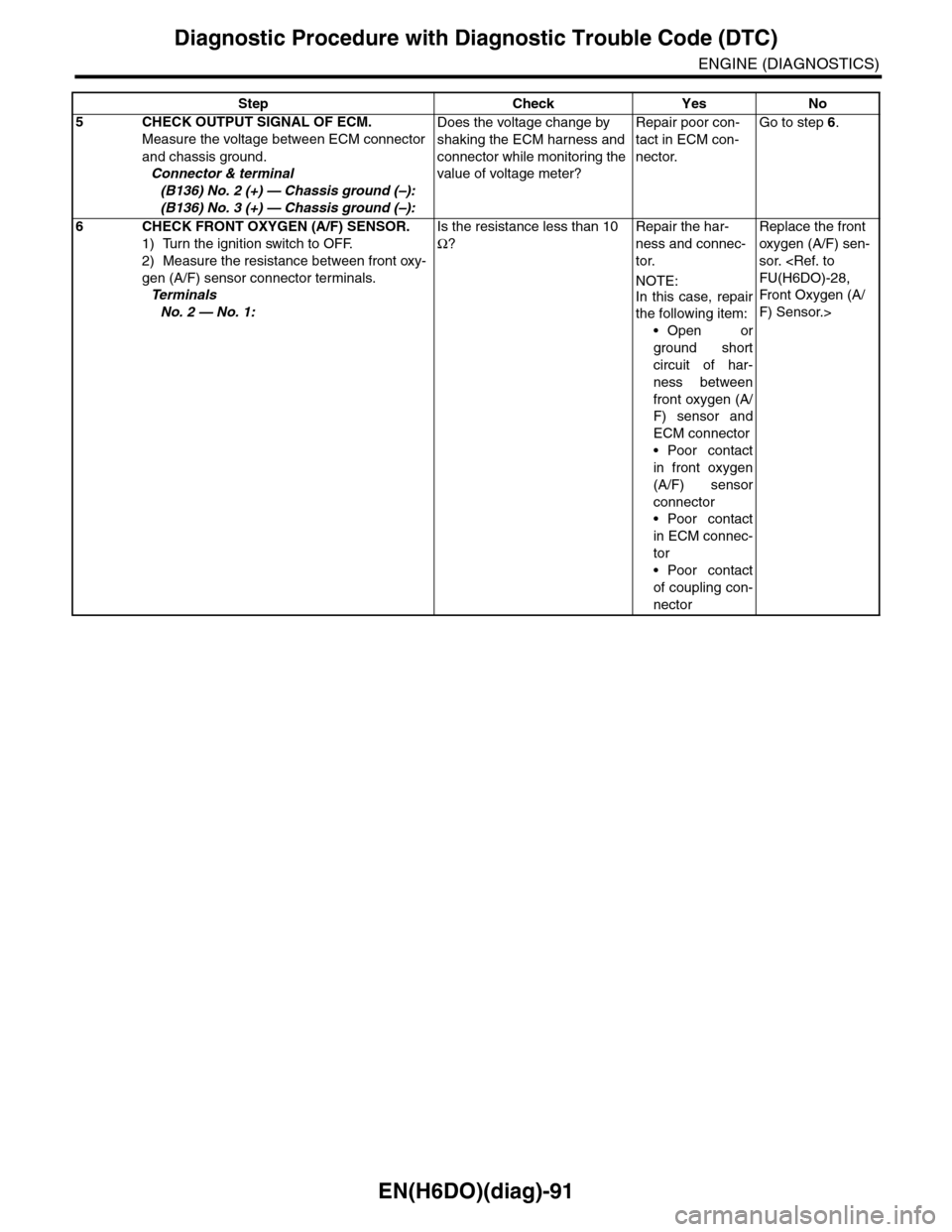
EN(H6DO)(diag)-91
Diagnostic Procedure with Diagnostic Trouble Code (DTC)
ENGINE (DIAGNOSTICS)
5CHECK OUTPUT SIGNAL OF ECM.
Measure the voltage between ECM connector
and chassis ground.
Connector & terminal
(B136) No. 2 (+) — Chassis ground (–):
(B136) No. 3 (+) — Chassis ground (–):
Does the voltage change by
shaking the ECM harness and
connector while monitoring the
value of voltage meter?
Repair poor con-
tact in ECM con-
nector.
Go to step 6.
6CHECK FRONT OXYGEN (A/F) SENSOR.
1) Turn the ignition switch to OFF.
2) Measure the resistance between front oxy-
gen (A/F) sensor connector terminals.
Te r m i n a l s
No. 2 — No. 1:
Is the resistance less than 10
Ω?
Repair the har-
ness and connec-
tor.
NOTE:
In this case, repair
the following item:
•Open or
ground short
circuit of har-
ness between
front oxygen (A/
F) sensor and
ECM connector
•Poor contact
in front oxygen
(A/F) sensor
connector
•Poor contact
in ECM connec-
tor
•Poor contact
of coupling con-
nector
Replace the front
oxygen (A/F) sen-
sor.
Fr o nt Ox yg en ( A /
F) Sensor.>
Step Check Yes No
Page 1254 of 2453
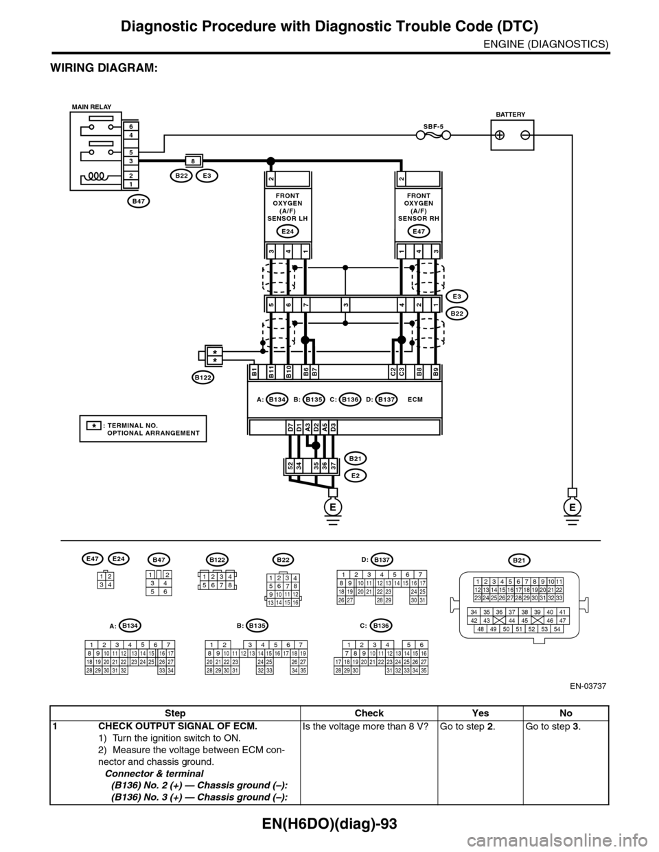
EN(H6DO)(diag)-93
Diagnostic Procedure with Diagnostic Trouble Code (DTC)
ENGINE (DIAGNOSTICS)
WIRING DIAGRAM:
EN-03737
SBF-5
B47
12
35
46
A3D1D7D2A5D3
2
3736353452B21
E2
ECM
B11B1B10B6B7C2C3B8B9
413
E24
2
431
E47
E3B22
8
56E3
B222134
B47
3456
12
B22
1234567891011 121314 15 16
3412
E47E24
B135
567821943102422 23 2511 12 13 14 1526 2728
16 17 18 1920 2129 30 31 32 33 34 35
B:
B21
123412131415567816171819910 1120212223 24 25 2627 28 29 3031 32 33
3534 37363938 41404342 4445 47464948 51505352 54
EE
B135B:B136C:B137D:B134A:
7
FRONTOXYGEN(A/F)SENSOR LH
FRONTOXYGEN(A/F)SENSOR RH
MAIN RELAYBATTERY
B136
16101112131415252430
9871718192028212223293231
123456
2726333435
C:
B137
85610 11 12 13 14 157213416
3019 20 2228 29
91718 2521 23 243126 27
D:B122
34561278
*: TERMINAL NO. OPTIONAL ARRANGEMENT
**
B122
A:B134
85610 11 12 13 14 157213416
3019 20 2228 29
91718252123 24323126 2733 34
Step Check Yes No
1CHECK OUTPUT SIGNAL OF ECM.
1) Turn the ignition switch to ON.
2) Measure the voltage between ECM con-
nector and chassis ground.
Connector & terminal
(B136) No. 2 (+) — Chassis ground (–):
(B136) No. 3 (+) — Chassis ground (–):
Is the voltage more than 8 V? Go to step 2.Go to step 3.
Page 1255 of 2453
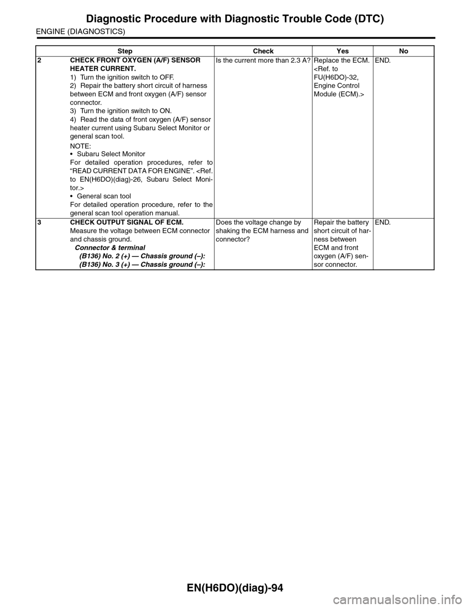
EN(H6DO)(diag)-94
Diagnostic Procedure with Diagnostic Trouble Code (DTC)
ENGINE (DIAGNOSTICS)
2CHECK FRONT OXYGEN (A/F) SENSOR
HEATER CURRENT.
1) Turn the ignition switch to OFF.
2) Repair the battery short circuit of harness
between ECM and front oxygen (A/F) sensor
connector.
3) Turn the ignition switch to ON.
4) Read the data of front oxygen (A/F) sensor
heater current using Subaru Select Monitor or
general scan tool.
NOTE:•Subaru Select Monitor
For detailed operation procedures, refer to
“READ CURRENT DATA FOR ENGINE”.
tor.>
•General scan tool
For detailed operation procedure, refer to the
general scan tool operation manual.
Is the current more than 2.3 A? Replace the ECM.
Engine Control
Module (ECM).>
END.
3CHECK OUTPUT SIGNAL OF ECM.
Measure the voltage between ECM connector
and chassis ground.
Connector & terminal
(B136) No. 2 (+) — Chassis ground (–):
(B136) No. 3 (+) — Chassis ground (–):
Does the voltage change by
shaking the ECM harness and
connector?
Repair the battery
short circuit of har-
ness between
ECM and front
oxygen (A/F) sen-
sor connector.
END.
Step Check Yes No