2009 SUBARU TRIBECA change time
[x] Cancel search: change timePage 1734 of 2453
GD(H6DO)-122
Diagnostic Trouble Code (DTC) Detecting Criteria
GENERAL DESCRIPTION
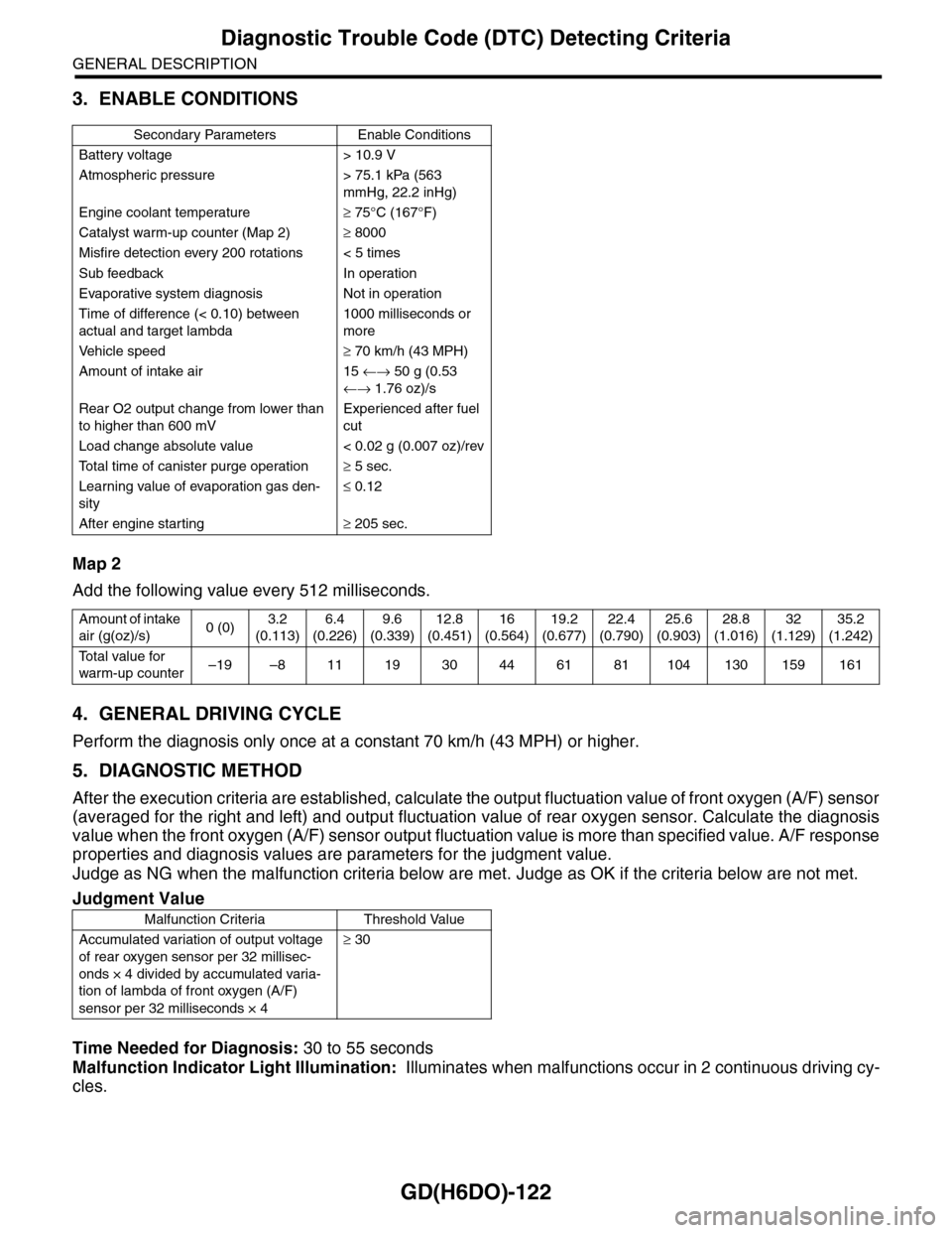
3. ENABLE CONDITIONS
Map 2
Add the following value every 512 milliseconds.
4. GENERAL DRIVING CYCLE
Perform the diagnosis only once at a constant 70 km/h (43 MPH) or higher.
5. DIAGNOSTIC METHOD
After the execution criteria are established, calculate the output fluctuation value of front oxygen (A/F) sensor
(averaged for the right and left) and output fluctuation value of rear oxygen sensor. Calculate the diagnosis
value when the front oxygen (A/F) sensor output fluctuation value is more than specified value. A/F response
properties and diagnosis values are parameters for the judgment value.
Judge as NG when the malfunction criteria below are met. Judge as OK if the criteria below are not met.
Time Needed for Diagnosis: 30 to 55 seconds
Malfunction Indicator Light Illumination: Illuminates when malfunctions occur in 2 continuous driving cy-
cles.
Secondary Parameters Enable Conditions
Battery voltage > 10.9 V
Atmospheric pressure > 75.1 kPa (563
mmHg, 22.2 inHg)
Engine coolant temperature≥ 75°C (167°F)
Catalyst warm-up counter (Map 2)≥ 8000
Misfire detection every 200 rotations < 5 times
Sub feedback In operation
Evaporative system diagnosis Not in operation
Time of difference (< 0.10) between
actual and target lambda
1000 milliseconds or
more
Ve h i c l e s p e e d≥ 70 km/h (43 MPH)
Amount of intake air 15 ←→ 50 g (0.53
←→ 1.76 oz)/s
Rear O2 output change from lower than
to higher than 600 mV
Experienced after fuel
cut
Load change absolute value < 0.02 g (0.007 oz)/rev
To t a l t i m e o f c a n i s t e r p u r g e o p e r a t i o n≥ 5 sec.
Learning value of evaporation gas den-
sity
≤ 0.12
After engine starting≥ 205 sec.
Amount of intake
air (g(oz)/s)0 (0)3.2
(0.113)
6.4
(0.226)
9.6
(0.339)
12.8
(0.451)
16
(0.564)
19.2
(0.677)
22.4
(0.790)
25.6
(0.903)
28.8
(1.016)
32
(1.129)
35.2
(1.242)
To t a l v a l u e f o r
warm-up counter–19 –8 11 19 30 44 61 81 104 130 159 161
Judgment Value
Malfunction Criteria Threshold Value
Accumulated variation of output voltage
of rear oxygen sensor per 32 millisec-
onds × 4 divided by accumulated varia-
tion of lambda of front oxygen (A/F)
sensor per 32 milliseconds × 4
≥ 30
Page 1738 of 2453
GD(H6DO)-126
Diagnostic Trouble Code (DTC) Detecting Criteria
GENERAL DESCRIPTION
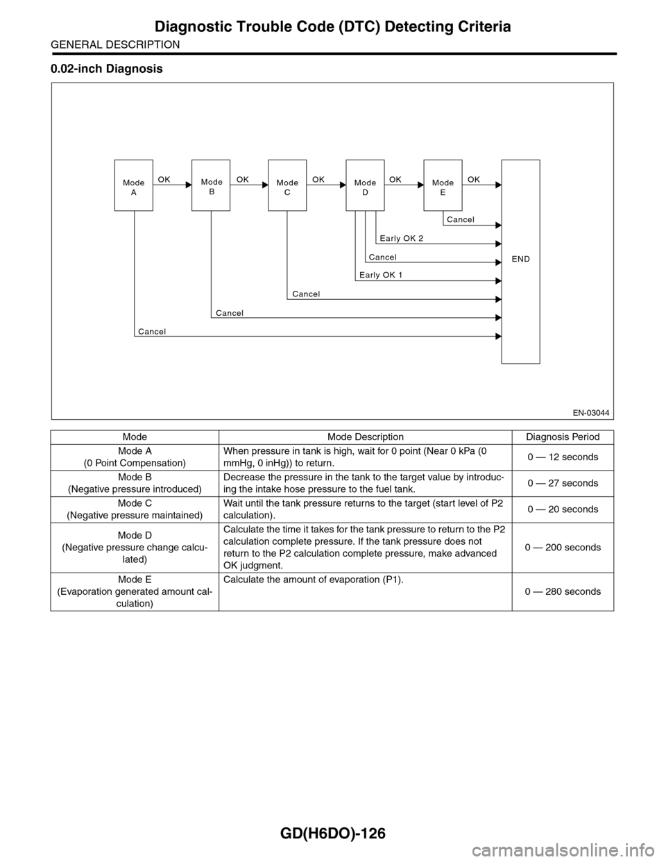
0.02-inch Diagnosis
Mode Mode Description Diagnosis Period
Mode A
(0 Point Compensation)
When pressure in tank is high, wait for 0 point (Near 0 kPa (0
mmHg, 0 inHg)) to return.0 — 12 seconds
Mode B
(Negative pressure introduced)
Decrease the pressure in the tank to the target value by introduc-
ing the intake hose pressure to the fuel tank.0 — 27 seconds
Mode C
(Negative pressure maintained)
Wa i t u nt i l t h e t a nk pr e ss ur e r et u r ns to t he t ar g e t ( s ta r t leve l o f P 2
calculation).0 — 20 seconds
Mode D
(Negative pressure change calcu-
lated)
Calculate the time it takes for the tank pressure to return to the P2
calculation complete pressure. If the tank pressure does not
return to the P2 calculation complete pressure, make advanced
OK judgment.
0 — 200 seconds
Mode E
(Evaporation generated amount cal-
culation)
Calculate the amount of evaporation (P1).
0 — 280 seconds
EN-03044
ModeAModeBModeCModeD
OKOKOK
Early OK 1
Cancel
Cancel
END
Cancel
Cancel
Early OK 2
OKModeE
Cancel
OK
Page 1740 of 2453
GD(H6DO)-128
Diagnostic Trouble Code (DTC) Detecting Criteria
GENERAL DESCRIPTION
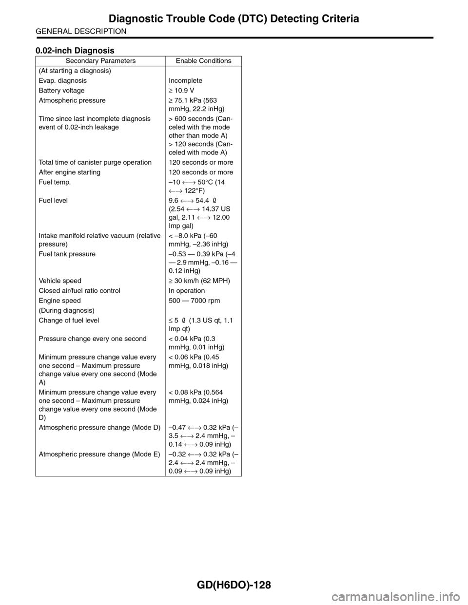
0.02-inch Diagnosis
Secondary Parameters Enable Conditions
(At starting a diagnosis)
Evap. diagnosis Incomplete
Battery voltage≥ 10.9 V
Atmospheric pressure≥ 75.1 kPa (563
mmHg, 22.2 inHg)
Time since last incomplete diagnosis
event of 0.02-inch leakage
> 600 seconds (Can-
celed with the mode
other than mode A)
> 120 seconds (Can-
celed with mode A)
To t a l t i m e o f c a n i s t e r p u r g e o p e r a t i o n 1 2 0 s e c o n d s o r m o r e
After engine starting 120 seconds or more
Fuel temp. –10 ←→ 50°C (14
←→ 122°F)
Fuel level 9.6 ←→ 54.4 2
(2.54 ←→ 14.37 US
gal, 2.11 ←→ 12.00
Imp gal)
Intake manifold relative vacuum (relative
pressure)
< –8.0 kPa (–60
mmHg, –2.36 inHg)
Fuel tank pressure –0.53 — 0.39 kPa (–4
— 2.9 mmHg, –0.16 —
0.12 inHg)
Ve h i c l e s p e e d≥ 30 km/h (62 MPH)
Closed air/fuel ratio control In operation
Engine speed 500 — 7000 rpm
(During diagnosis)
Change of fuel level≤ 5 2 (1.3 US qt, 1.1
Imp qt)
Pressure change every one second < 0.04 kPa (0.3
mmHg, 0.01 inHg)
Minimum pressure change value every
one second – Maximum pressure
change value every one second (Mode
A)
< 0.06 kPa (0.45
mmHg, 0.018 inHg)
Minimum pressure change value every
one second – Maximum pressure
change value every one second (Mode
D)
< 0.08 kPa (0.564
mmHg, 0.024 inHg)
Atmospheric pressure change (Mode D) –0.47 ←→ 0.32 kPa (–
3.5 ←→ 2.4 mmHg, –
0.14 ←→ 0.09 inHg)
Atmospheric pressure change (Mode E) –0.32 ←→ 0.32 kPa (–
2.4 ←→ 2.4 mmHg, –
0.09 ←→ 0.09 inHg)
Page 1742 of 2453
GD(H6DO)-130
Diagnostic Trouble Code (DTC) Detecting Criteria
GENERAL DESCRIPTION
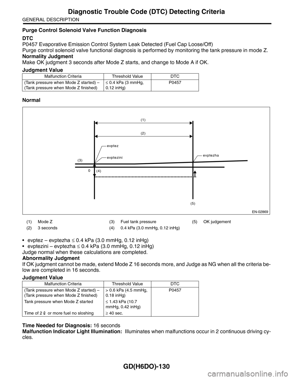
Purge Control Solenoid Valve Function Diagnosis
DTC
P0457 Evaporative Emission Control System Leak Detected (Fuel Cap Loose/Off)
Purge control solenoid valve functional diagnosis is performed by monitoring the tank pressure in mode Z.
Normality Judgment
Make OK judgment 3 seconds after Mode Z starts, and change to Mode A if OK.
Normal
•evptez – evptezha ≤ 0.4 kPa (3.0 mmHg, 0.12 inHg)
•evptezini – evptezha ≤ 0.4 kPa (3.0 mmHg, 0.12 inHg)
Judge normal when these calculations are completed.
Abnormality Judgment
If OK judgment cannot be made, extend Mode Z 16 seconds more, and Judge as NG when all the criteria be-
low are completed in 16 seconds.
Time Needed for Diagnosis: 16 seconds
Malfunction Indicator Light Illumination: Illuminates when malfunctions occur in 2 continuous driving cy-
cles.
Judgment Value
Malfunction Criteria Threshold Value DTC
(Tank pressure when Mode Z started) –
(Tank pressure when Mode Z finished)
≤ 0.4 kPa (3 mmHg,
0.12 inHg)
P0457
(1) Mode Z (3) Fuel tank pressure (5) OK judgement
(2) 3 seconds (4) 0.4 kPa (3.0 mmHg, 0.12 inHg)
Judgment Value
Malfunction Criteria Threshold Value DTC
(Tank pressure when Mode Z started) –
(Tank pressure when Mode Z finished)
> 0.6 kPa (4.5 mmHg,
0.18 inHg)
P0457
Ta n k p r e s s u r e w h e n M o d e Z s t a r t e d≤ 1.43 kPa (10.7
mmHg, 0.42 inHg)
Time of 22 or more fuel no sloshing≥ 40 sec.
EN-02869
(1)
(2)
(4)
evptez
evptezinievptezha
0
(3)
(5)
Page 1744 of 2453
GD(H6DO)-132
Diagnostic Trouble Code (DTC) Detecting Criteria
GENERAL DESCRIPTION
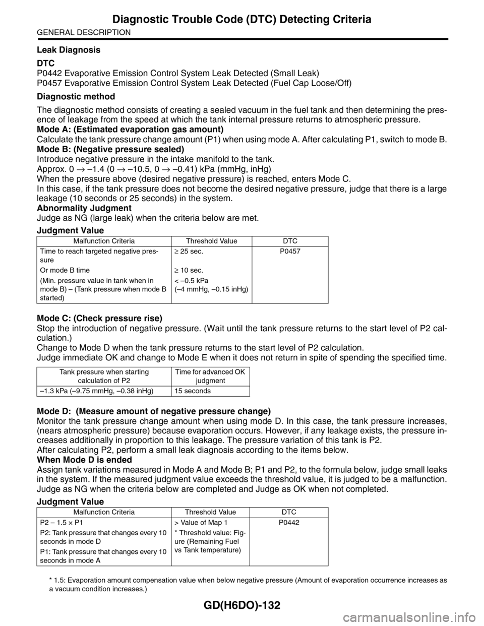
Leak Diagnosis
DTC
P0442 Evaporative Emission Control System Leak Detected (Small Leak)
P0457 Evaporative Emission Control System Leak Detected (Fuel Cap Loose/Off)
Diagnostic method
The diagnostic method consists of creating a sealed vacuum in the fuel tank and then determining the pres-
ence of leakage from the speed at which the tank internal pressure returns to atmospheric pressure.
Mode A: (Estimated evaporation gas amount)
Calculate the tank pressure change amount (P1) when using mode A. After calculating P1, switch to mode B.
Mode B: (Negative pressure sealed)
Introduce negative pressure in the intake manifold to the tank.
Approx. 0 → –1.4 (0 → –10.5, 0 → –0.41) kPa (mmHg, inHg)
When the pressure above (desired negative pressure) is reached, enters Mode C.
In this case, if the tank pressure does not become the desired negative pressure, judge that there is a large
leakage (10 seconds or 25 seconds) in the system.
Abnormality Judgment
Judge as NG (large leak) when the criteria below are met.
Mode C: (Check pressure rise)
Stop the introduction of negative pressure. (Wait until the tank pressure returns to the start level of P2 cal-
culation.)
Change to Mode D when the tank pressure returns to the start level of P2 calculation.
Judge immediate OK and change to Mode E when it does not return in spite of spending the specified time.
Mode D: (Measure amount of negative pressure change)
Monitor the tank pressure change amount when using mode D. In this case, the tank pressure increases,
(nears atmospheric pressure) because evaporation occurs. However, if any leakage exists, the pressure in-
creases additionally in proportion to this leakage. The pressure variation of this tank is P2.
After calculating P2, perform a small leak diagnosis according to the items below.
When Mode D is ended
Assign tank variations measured in Mode A and Mode B; P1 and P2, to the formula below, judge small leaks
in the system. If the measured judgment value exceeds the threshold value, it is judged to be a malfunction.
Judge as NG when the criteria below are completed and Judge as OK when not completed.
* 1.5: Evaporation amount compensation value when below negative pressure (Amount of evaporation occurrence increases as
a vacuum condition increases.)
Judgment Value
Malfunction Criteria Threshold Value DTC
Time to reach targeted negative pres-
sure
≥ 25 sec. P0457
Or mode B time≥ 10 sec.
(Min. pressure value in tank when in
mode B) – (Tank pressure when mode B
started)
< –0.5 kPa
(–4 mmHg, –0.15 inHg)
Ta n k p r e s s u r e w h e n s t a r t i n g
calculation of P2
Time for advanced OK
judgment
–1.3 kPa (–9.75 mmHg, –0.38 inHg) 15 seconds
Judgment Value
Malfunction Criteria Threshold Value DTC
P2 – 1.5 × P1 > Value of Map 1 P0442
P2: Tank pressure that changes every 10
seconds in mode D
* Threshold value: Fig-
ure (Remaining Fuel
vs Tank temperature)
P1: Tank pressure that changes every 10
seconds in mode A
Page 1745 of 2453
GD(H6DO)-133
Diagnostic Trouble Code (DTC) Detecting Criteria
GENERAL DESCRIPTION
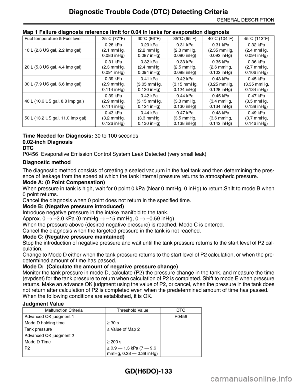
Time Needed for Diagnosis: 30 to 100 seconds
0.02-inch Diagnosis
DTC
P0456 Evaporative Emission Control System Leak Detected (very small leak)
Diagnostic method
The diagnostic method consists of creating a sealed vacuum in the fuel tank and then determining the pres-
ence of leakage from the speed at which the tank internal pressure returns to atmospheric pressure.
Mode A: (0 Point Compensation)
When pressure in tank is high, wait for 0 point 0 kPa (Near 0 mmHg, 0 inHg) to return.Shift to mode B when
0 point returns.
Cancel the diagnosis when 0 point does not return in the specified time.
Mode B: (Negative pressure introduced)
Introduce negative pressure in the intake manifold to the tank.
Approx. 0 → –2.0 kPa (0 mmHg → –15 mmHg, 0 → –0.59 inHg)
When the pressure above (desired negative pressure) is reached, Mode C is entered.
Cancel the diagnosis when the targeted pressure in the tank is not reached.
Mode C: (Negative pressure maintained)
Stop the introduction of negative pressure and wait until the tank pressure returns to the start level of P2 cal-
culation.
Change to Mode D either when the tank pressure returns to the start level of P2 calculation, or when the pre-
determined amount of time has passed.
Mode D: (Calculate the amount of negative pressure change)
Monitor the tank pressure in mode D, calculate (P2) the pressure change in the tank, and measure the time
(evpdset) for the tank pressure to return when calculation of P2 is completed. Shift to mode E when pressure
returns. Make an advance OK judgment using the value of P2, or cancel, when the pressure in the tank does
not return after calculation of P2 is completed even when the predetermined amount of time has passed.
When the following conditions are established, it is OK.
Map 1 Failure diagnosis reference limit for 0.04 in leaks for evaporation diagnosis
Fuel temperature & Fuel level 25°C (77°F) 30°C (86°F) 35°C (95°F) 40°C (104°F) 45°C (113°F)
10 L (2.6 US gal, 2.2 Imp gal)
0.28 kPa
(2.1 mmHg,
0.083 inHg)
0.29 kPa
(2.2 mmHg,
0.087 inHg)
0.31 kPa
(2.3 mmHg,
0.090 inHg)
0.31 kPa
(2.35 mmHg,
0.092 inHg)
0.32 kPa
(2.4 mmHg,
0.094 inHg)
20 L (5.3 US gal, 4.4 Imp gal)
0.31 kPa
(2.3 mmHg,
0.091 inHg)
0.32 kPa
(2.4 mmHg,
0.094 inHg)
0.33 kPa
(2.5 mmHg,
0.098 inHg)
0.35 kPa
(2.6 mmHg,
0.102 inHg)
0.36 kPa
(2.7 mmHg,
0.106 inHg)
30 L (7.9 US gal, 6.6 Imp gal)
0.39 kPa
(2.9 mmHg,
0.114 inHg)
0.41 kPa
(3.05 mmHg,
0.120 inHg)
0.42 kPa
(3.15 mmHg,
0.124 inHg)
0.43 kPa
(3.25 mmHg,
0.128 inHg)
0.45 kPa
(3.35 mmHg,
0.134 inHg)
40 L (10.6 US gal, 8.8 Imp gal)
0.39 kPa
(2.9 mmHg,
0.114 inHg)
0.42 kPa
(3.15 mmHg,
0.124 inHg)
0.44 kPa
(3.3 mmHg,
0.130 inHg)
0.45 kPa
(3.4 mmHg,
0.134 inHg)
0.47 kPa
(3.5 mmHg,
0.138 inHg)
50 L (13.2 US gal, 11.0 Imp gal)
0.43 kPa
(3.2 mmHg,
0.126 inHg)
0.44 kPa
(3.3 mmHg,
0.130 inHg)
0.47 kPa
(3.5 mmHg,
0.138 inHg)
0.48 kPa
(3.6 mmHg,
0.142 inHg)
0.49 kPa
(3.7 mmHg,
0.146 inHg)
Judgment Value
Malfunction Criteria Threshold Value DTC
Advanced OK judgment 1 P0456
Mode D holding time≥ 30 s
Ta n k p r e s s u r e≤ Value of Map 2
Advanced OK judgment 2
Mode D Time≥ 200 s
P2≥ 0.9 — 1.3 kPa (7 — 9.6
mmHg, 0.28 — 0.38 inHg)
Page 1746 of 2453
GD(H6DO)-134
Diagnostic Trouble Code (DTC) Detecting Criteria
GENERAL DESCRIPTION
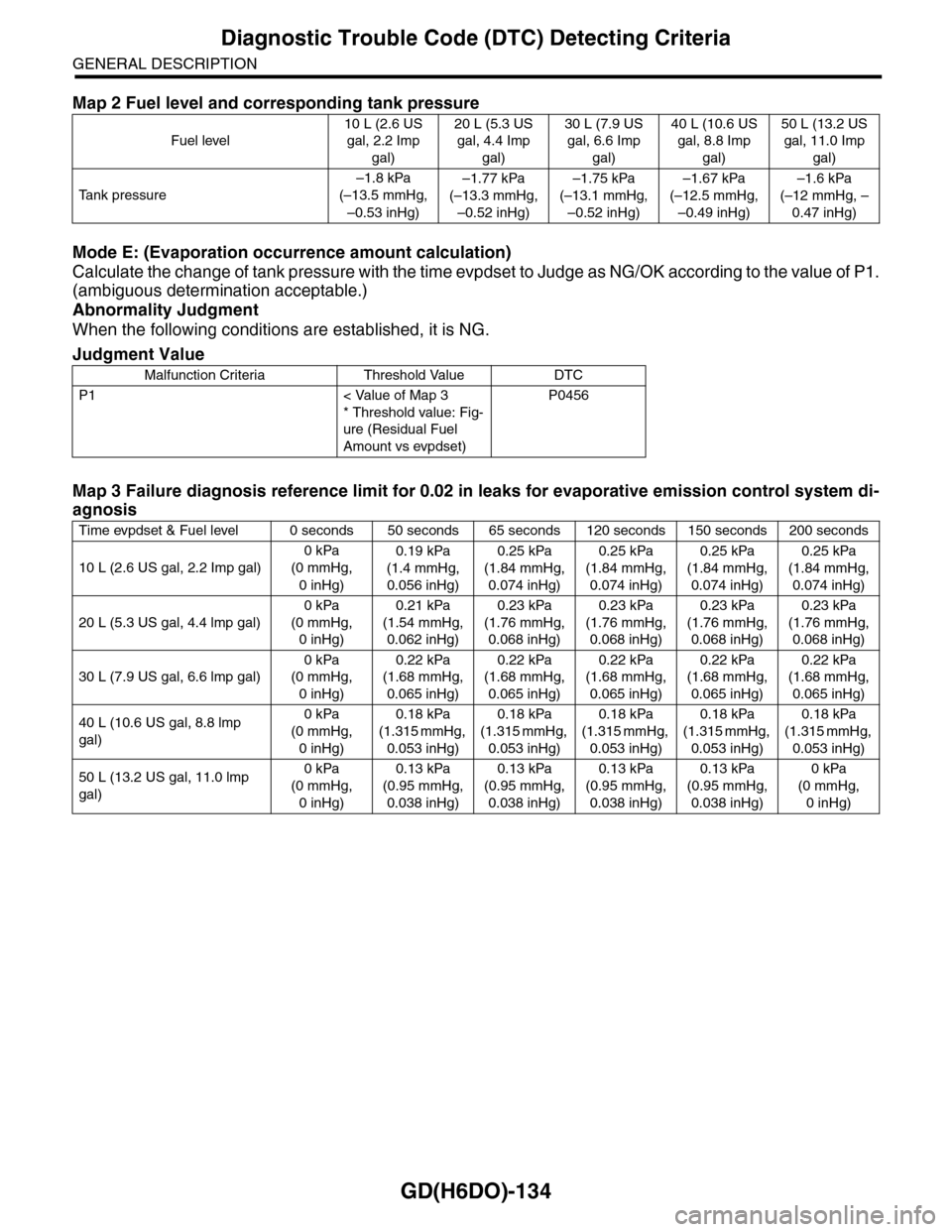
Mode E: (Evaporation occurrence amount calculation)
Calculate the change of tank pressure with the time evpdset to Judge as NG/OK according to the value of P1.
(ambiguous determination acceptable.)
Abnormality Judgment
When the following conditions are established, it is NG.
Map 2 Fuel level and corresponding tank pressure
Fuel level
10 L (2.6 US
gal, 2.2 Imp
gal)
20 L (5.3 US
gal, 4.4 Imp
gal)
30 L (7.9 US
gal, 6.6 Imp
gal)
40 L (10.6 US
gal, 8.8 Imp
gal)
50 L (13.2 US
gal, 11.0 Imp
gal)
Ta n k p r e s s u r e
–1.8 kPa
(–13.5 mmHg,
–0.53 inHg)
–1.77 kPa
(–13.3 mmHg,
–0.52 inHg)
–1.75 kPa
(–13.1 mmHg,
–0.52 inHg)
–1.67 kPa
(–12.5 mmHg,
–0.49 inHg)
–1.6 kPa
(–12 mmHg, –
0.47 inHg)
Judgment Value
Malfunction Criteria Threshold Value DTC
P1 < Value of Map 3
* Threshold value: Fig-
ure (Residual Fuel
Amount vs evpdset)
P0456
Map 3 Failure diagnosis reference limit for 0.02 in leaks for evaporative emission control system di-
agnosis
Time evpdset & Fuel level 0 seconds 50 seconds 65 seconds 120 seconds 150 seconds 200 seconds
10 L (2.6 US gal, 2.2 Imp gal)
0 kPa
(0 mmHg,
0 inHg)
0.19 kPa
(1.4 mmHg,
0.056 inHg)
0.25 kPa
(1.84 mmHg,
0.074 inHg)
0.25 kPa
(1.84 mmHg,
0.074 inHg)
0.25 kPa
(1.84 mmHg,
0.074 inHg)
0.25 kPa
(1.84 mmHg,
0.074 inHg)
20 L (5.3 US gal, 4.4 lmp gal)
0 kPa
(0 mmHg,
0 inHg)
0.21 kPa
(1.54 mmHg,
0.062 inHg)
0.23 kPa
(1.76 mmHg,
0.068 inHg)
0.23 kPa
(1.76 mmHg,
0.068 inHg)
0.23 kPa
(1.76 mmHg,
0.068 inHg)
0.23 kPa
(1.76 mmHg,
0.068 inHg)
30 L (7.9 US gal, 6.6 lmp gal)
0 kPa
(0 mmHg,
0 inHg)
0.22 kPa
(1.68 mmHg,
0.065 inHg)
0.22 kPa
(1.68 mmHg,
0.065 inHg)
0.22 kPa
(1.68 mmHg,
0.065 inHg)
0.22 kPa
(1.68 mmHg,
0.065 inHg)
0.22 kPa
(1.68 mmHg,
0.065 inHg)
40 L (10.6 US gal, 8.8 lmp
gal)
0 kPa
(0 mmHg,
0 inHg)
0.18 kPa
(1.315 mmHg,
0.053 inHg)
0.18 kPa
(1.315 mmHg,
0.053 inHg)
0.18 kPa
(1.315 mmHg,
0.053 inHg)
0.18 kPa
(1.315 mmHg,
0.053 inHg)
0.18 kPa
(1.315 mmHg,
0.053 inHg)
50 L (13.2 US gal, 11.0 lmp
gal)
0 kPa
(0 mmHg,
0 inHg)
0.13 kPa
(0.95 mmHg,
0.038 inHg)
0.13 kPa
(0.95 mmHg,
0.038 inHg)
0.13 kPa
(0.95 mmHg,
0.038 inHg)
0.13 kPa
(0.95 mmHg,
0.038 inHg)
0 kPa
(0 mmHg,
0 inHg)
Page 1771 of 2453
GD(H6DO)-159
Diagnostic Trouble Code (DTC) Detecting Criteria
GENERAL DESCRIPTION
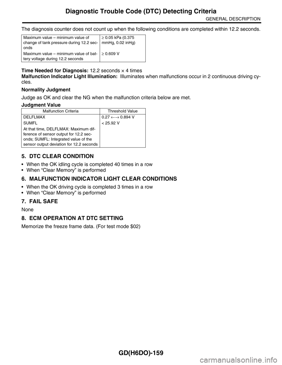
The diagnosis counter does not count up when the following conditions are completed within 12.2 seconds.
Time Needed for Diagnosis: 12.2 seconds × 4 times
Malfunction Indicator Light Illumination: Illuminates when malfunctions occur in 2 continuous driving cy-
cles.
Normality Judgment
Judge as OK and clear the NG when the malfunction criteria below are met.
5. DTC CLEAR CONDITION
•When the OK idling cycle is completed 40 times in a row
•When “Clear Memory” is performed
6. MALFUNCTION INDICATOR LIGHT CLEAR CONDITIONS
•When the OK driving cycle is completed 3 times in a row
•When “Clear Memory” is performed
7. FAIL SAFE
None
8. ECM OPERATION AT DTC SETTING
Memorize the freeze frame data. (For test mode $02)
Maximum value – minimum value of
change of tank pressure during 12.2 sec-
onds
≥ 0.05 kPa (0.375
mmHg, 0.02 inHg)
Maximum value – minimum value of bat-
tery voltage during 12.2 seconds
≥ 0.609 V
Judgment Value
Malfunction Criteria Threshold Value
DELFLMAX 0.27 ←→ 0.894 V
SUMFL < 25.92 V
At that time, DELFLMAX: Maximum dif-
ference of sensor output for 12.2 sec-
onds; SUMFL: Integrated value of the
sensor output deviation for 12.2 seconds