2009 SUBARU TRIBECA change time
[x] Cancel search: change timePage 1772 of 2453
GD(H6DO)-160
Diagnostic Trouble Code (DTC) Detecting Criteria
GENERAL DESCRIPTION
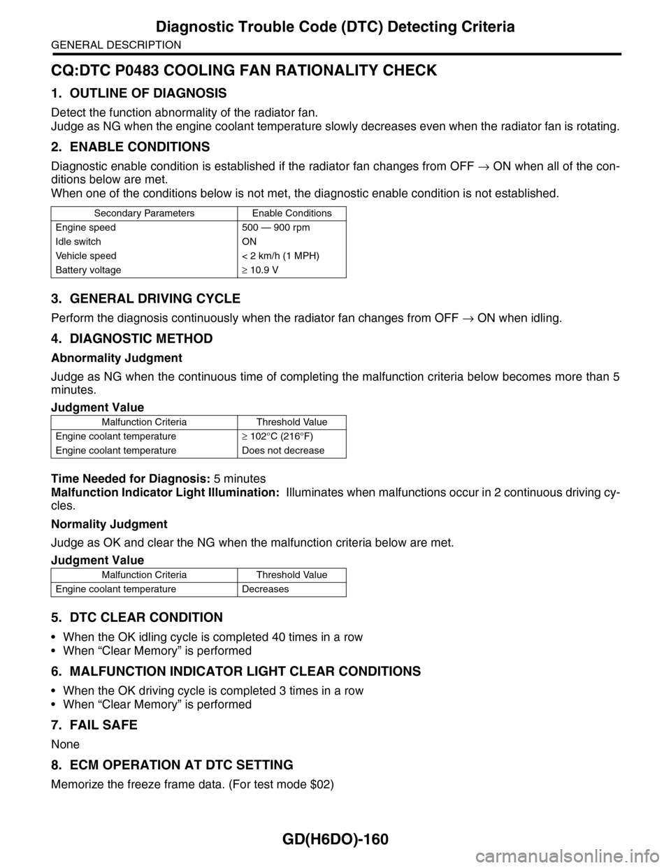
CQ:DTC P0483 COOLING FAN RATIONALITY CHECK
1. OUTLINE OF DIAGNOSIS
Detect the function abnormality of the radiator fan.
Judge as NG when the engine coolant temperature slowly decreases even when the radiator fan is rotating.
2. ENABLE CONDITIONS
Diagnostic enable condition is established if the radiator fan changes from OFF → ON when all of the con-
ditions below are met.
When one of the conditions below is not met, the diagnostic enable condition is not established.
3. GENERAL DRIVING CYCLE
Perform the diagnosis continuously when the radiator fan changes from OFF → ON when idling.
4. DIAGNOSTIC METHOD
Abnormality Judgment
Judge as NG when the continuous time of completing the malfunction criteria below becomes more than 5
minutes.
Time Needed for Diagnosis: 5 minutes
Malfunction Indicator Light Illumination: Illuminates when malfunctions occur in 2 continuous driving cy-
cles.
Normality Judgment
Judge as OK and clear the NG when the malfunction criteria below are met.
5. DTC CLEAR CONDITION
•When the OK idling cycle is completed 40 times in a row
•When “Clear Memory” is performed
6. MALFUNCTION INDICATOR LIGHT CLEAR CONDITIONS
•When the OK driving cycle is completed 3 times in a row
•When “Clear Memory” is performed
7. FAIL SAFE
None
8. ECM OPERATION AT DTC SETTING
Memorize the freeze frame data. (For test mode $02)
Secondary Parameters Enable Conditions
Engine speed 500 — 900 rpm
Idle switch ON
Ve h i c l e s p e e d < 2 k m / h ( 1 M P H )
Battery voltage≥ 10.9 V
Judgment Value
Malfunction Criteria Threshold Value
Engine coolant temperature≥ 102°C (216°F)
Engine coolant temperature Does not decrease
Judgment Value
Malfunction Criteria Threshold Value
Engine coolant temperature Decreases
Page 1775 of 2453
GD(H6DO)-163
Diagnostic Trouble Code (DTC) Detecting Criteria
GENERAL DESCRIPTION
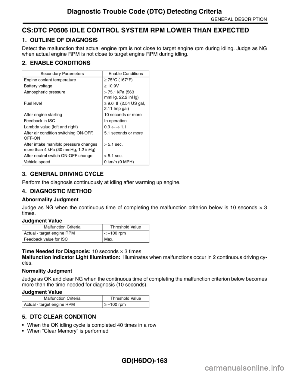
CS:DTC P0506 IDLE CONTROL SYSTEM RPM LOWER THAN EXPECTED
1. OUTLINE OF DIAGNOSIS
Detect the malfunction that actual engine rpm is not close to target engine rpm during idling. Judge as NG
when actual engine RPM is not close to target engine RPM during idling.
2. ENABLE CONDITIONS
3. GENERAL DRIVING CYCLE
Perform the diagnosis continuously at idling after warming up engine.
4. DIAGNOSTIC METHOD
Abnormality Judgment
Judge as NG when the continuous time of completing the malfunction criterion below is 10 seconds × 3
times.
Time Needed for Diagnosis: 10 seconds × 3 times
Malfunction Indicator Light Illumination: Illuminates when malfunctions occur in 2 continuous driving cy-
cles.
Normality Judgment
Judge as OK and clear NG when the continuous time of completing the malfunction criterion below becomes
more than the time needed for diagnosis (10 seconds).
5. DTC CLEAR CONDITION
•When the OK idling cycle is completed 40 times in a row
•When “Clear Memory” is performed
Secondary Parameters Enable Conditions
Engine coolant temperature≥ 75°C (167°F)
Battery voltage≥ 10.9V
Atmospheric pressure > 75.1 kPa (563
mmHg, 22.2 inHg)
Fuel level≥ 9.6 2 (2.54 US gal,
2.11 Imp gal)
After engine starting 10 seconds or more
Feedback in ISC In operation
Lambda value (left and right) 0.9 ←→ 1.1
After air condition switching ON-OFF,
OFF-ON
5.1 seconds or more
After intake manifold pressure changes
more than 4 kPa (30 mmHg, 1.2 inHg)
> 5.1 sec.
After neutral switch ON-OFF change > 5.1 sec.
Ve h i c l e s p e e d 0 k m / h ( 0 M P H )
Judgment Value
Malfunction Criteria Threshold Value
Actual - target engine RPM < –100 rpm
Feedback value for ISC Max.
Judgment Value
Malfunction Criteria Threshold Value
Actual - target engine RPM≥ –100 rpm
Page 1777 of 2453
GD(H6DO)-165
Diagnostic Trouble Code (DTC) Detecting Criteria
GENERAL DESCRIPTION
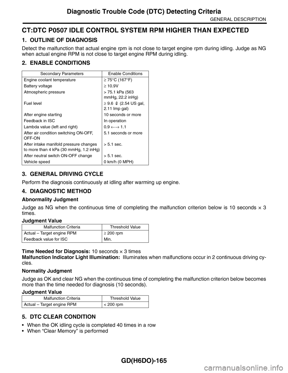
CT:DTC P0507 IDLE CONTROL SYSTEM RPM HIGHER THAN EXPECTED
1. OUTLINE OF DIAGNOSIS
Detect the malfunction that actual engine rpm is not close to target engine rpm during idling. Judge as NG
when actual engine RPM is not close to target engine RPM during idling.
2. ENABLE CONDITIONS
3. GENERAL DRIVING CYCLE
Perform the diagnosis continuously at idling after warming up engine.
4. DIAGNOSTIC METHOD
Abnormality Judgment
Judge as NG when the continuous time of completing the malfunction criterion below is 10 seconds × 3
times.
Time Needed for Diagnosis: 10 seconds × 3 times
Malfunction Indicator Light Illumination: Illuminates when malfunctions occur in 2 continuous driving cy-
cles.
Normality Judgment
Judge as OK and clear NG when the continuous time of completing the malfunction criterion below becomes
more than the time needed for diagnosis (10 seconds).
5. DTC CLEAR CONDITION
•When the OK idling cycle is completed 40 times in a row
•When “Clear Memory” is performed
Secondary Parameters Enable Conditions
Engine coolant temperature≥ 75°C (167°F)
Battery voltage≥ 10.9V
Atmospheric pressure > 75.1 kPa (563
mmHg, 22.2 inHg)
Fuel level≥ 9.6 2 (2.54 US gal,
2.11 Imp gal)
After engine starting 10 seconds or more
Feedback in ISC In operation
Lambda value (left and right) 0.9 ←→ 1.1
After air condition switching ON-OFF,
OFF-ON
5.1 seconds or more
After intake manifold pressure changes
to more than 4 kPa (30 mmHg, 1.2 inHg)
> 5.1 sec.
After neutral switch ON-OFF change > 5.1 sec.
Ve h i c l e s p e e d 0 k m / h ( 0 M P H )
Judgment Value
Malfunction Criteria Threshold Value
Actual – Target engine RPM≥ 200 rpm
Feedback value for ISC Min.
Judgment Value
Malfunction Criteria Threshold Value
Actual – Target engine RPM < 200 rpm
Page 1781 of 2453
GD(H6DO)-169
Diagnostic Trouble Code (DTC) Detecting Criteria
GENERAL DESCRIPTION
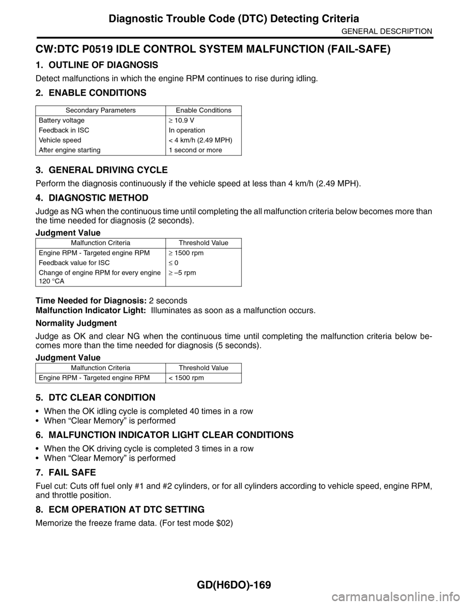
CW:DTC P0519 IDLE CONTROL SYSTEM MALFUNCTION (FAIL-SAFE)
1. OUTLINE OF DIAGNOSIS
Detect malfunctions in which the engine RPM continues to rise during idling.
2. ENABLE CONDITIONS
3. GENERAL DRIVING CYCLE
Perform the diagnosis continuously if the vehicle speed at less than 4 km/h (2.49 MPH).
4. DIAGNOSTIC METHOD
Judge as NG when the continuous time until completing the all malfunction criteria below becomes more than
the time needed for diagnosis (2 seconds).
Time Needed for Diagnosis: 2 seconds
Malfunction Indicator Light: Illuminates as soon as a malfunction occurs.
Normality Judgment
Judge as OK and clear NG when the continuous time until completing the malfunction criteria below be-
comes more than the time needed for diagnosis (5 seconds).
5. DTC CLEAR CONDITION
•When the OK idling cycle is completed 40 times in a row
•When “Clear Memory” is performed
6. MALFUNCTION INDICATOR LIGHT CLEAR CONDITIONS
•When the OK driving cycle is completed 3 times in a row
•When “Clear Memory” is performed
7. FAIL SAFE
Fuel cut: Cuts off fuel only #1 and #2 cylinders, or for all cylinders according to vehicle speed, engine RPM,
and throttle position.
8. ECM OPERATION AT DTC SETTING
Memorize the freeze frame data. (For test mode $02)
Secondary Parameters Enable Conditions
Battery voltage≥ 10.9 V
Feedback in ISC In operation
Ve h i c l e s p e e d < 4 k m / h ( 2 . 4 9 M P H )
After engine starting 1 second or more
Judgment Value
Malfunction Criteria Threshold Value
Engine RPM - Targeted engine RPM≥ 1500 rpm
Feedback value for ISC≤ 0
Change of engine RPM for every engine
120 °CA
≥ –5 rpm
Judgment Value
Malfunction Criteria Threshold Value
Engine RPM - Targeted engine RPM < 1500 rpm
Page 1795 of 2453
GD(H6DO)-183
Diagnostic Trouble Code (DTC) Detecting Criteria
GENERAL DESCRIPTION
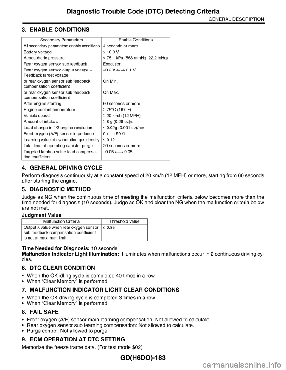
3. ENABLE CONDITIONS
4. GENERAL DRIVING CYCLE
Perform diagnosis continuously at a constant speed of 20 km/h (12 MPH) or more, starting from 60 seconds
after starting the engine.
5. DIAGNOSTIC METHOD
Judge as NG when the continuous time of meeting the malfunction criteria below becomes more than the
time needed for diagnosis (10 seconds). Judge as OK and clear the NG when the malfunction criteria below
are not met.
Time Needed for Diagnosis: 10 seconds
Malfunction Indicator Light Illumination: Illuminates when malfunctions occur in 2 continuous driving cy-
cles.
6. DTC CLEAR CONDITION
•When the OK idling cycle is completed 40 times in a row
•When “Clear Memory” is performed
7. MALFUNCTION INDICATOR LIGHT CLEAR CONDITIONS
•When the OK driving cycle is completed 3 times in a row
•When “Clear Memory” is performed
8. FAIL SAFE
•Front oxygen (A/F) sensor main learning compensation: Not allowed to calculate.
•Rear oxygen sensor sub learning compensation: Not allowed to calculate.
•Purge control: Not allowed to purge
9. ECM OPERATION AT DTC SETTING
Memorize the freeze frame data. (For test mode $02)
Secondary Parameters Enable Conditions
All secondary parameters enable conditions4 seconds or more
Battery voltage > 10.9 V
Atmospheric pressure > 75.1 kPa (563 mmHg, 22.2 inHg)
Rear oxygen sensor sub feedback Execution
Rear oxygen sensor output voltage –
Feedback target voltage
–0.2 V ←→ 0.1 V
or rear oxygen sensor sub feedback
compensation coefficient
On Min.
or rear oxygen sensor sub feedback
compensation coefficient
On Max.
After engine starting 60 seconds or more
Engine coolant temperature≥ 75°C (167°F)
Ve h i c l e s p e e d≥ 20 km/h (12 MPH)
Amount of intake air≥ 8 g (0.28 oz)/s
Load change in 1/3 engine revolution.≤ 0.02g (0.001 oz)/rev
Fr o nt ox yg e n ( A / F) s en so r im pe d an c e 0 ←→ 50 Ω
Learning value of evaporation gas density≤ 0.12
To t a l t i m e o f o p e r a t i n g c a n i s t e r p u r g e 2 0 s e c o n d s o r m o r e
Ta r g e t e d l a m b d a v a l u e l o a d c o m p e n s a -
tion coefficient
–0.05 ←→ 0.05
Judgment Value
Malfunction Criteria Threshold Value
Output λ value when rear oxygen sensor
sub feedback compensation coefficient
is not at maximum limit
≤ 0.85
Page 1797 of 2453
GD(H6DO)-185
Diagnostic Trouble Code (DTC) Detecting Criteria
GENERAL DESCRIPTION
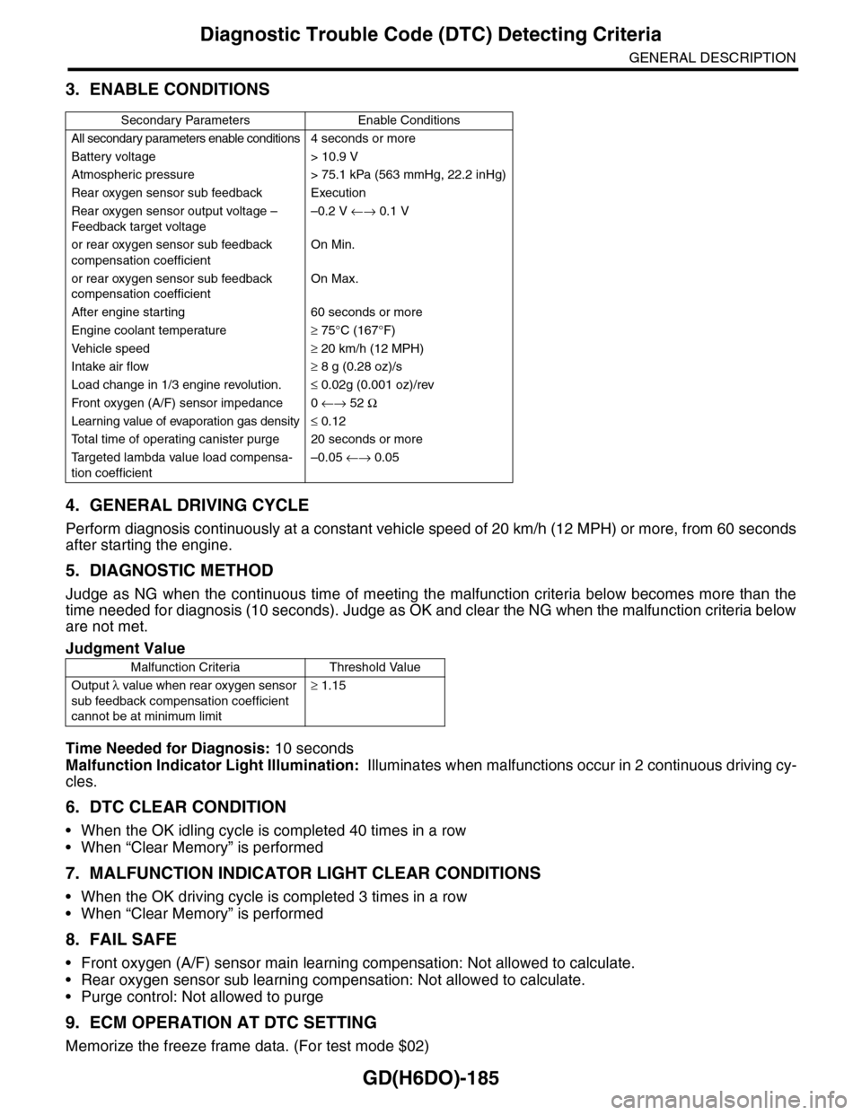
3. ENABLE CONDITIONS
4. GENERAL DRIVING CYCLE
Perform diagnosis continuously at a constant vehicle speed of 20 km/h (12 MPH) or more, from 60 seconds
after starting the engine.
5. DIAGNOSTIC METHOD
Judge as NG when the continuous time of meeting the malfunction criteria below becomes more than the
time needed for diagnosis (10 seconds). Judge as OK and clear the NG when the malfunction criteria below
are not met.
Time Needed for Diagnosis: 10 seconds
Malfunction Indicator Light Illumination: Illuminates when malfunctions occur in 2 continuous driving cy-
cles.
6. DTC CLEAR CONDITION
•When the OK idling cycle is completed 40 times in a row
•When “Clear Memory” is performed
7. MALFUNCTION INDICATOR LIGHT CLEAR CONDITIONS
•When the OK driving cycle is completed 3 times in a row
•When “Clear Memory” is performed
8. FAIL SAFE
•Front oxygen (A/F) sensor main learning compensation: Not allowed to calculate.
•Rear oxygen sensor sub learning compensation: Not allowed to calculate.
•Purge control: Not allowed to purge
9. ECM OPERATION AT DTC SETTING
Memorize the freeze frame data. (For test mode $02)
Secondary Parameters Enable Conditions
All secondary parameters enable conditions4 seconds or more
Battery voltage > 10.9 V
Atmospheric pressure > 75.1 kPa (563 mmHg, 22.2 inHg)
Rear oxygen sensor sub feedback Execution
Rear oxygen sensor output voltage –
Feedback target voltage
–0.2 V ←→ 0.1 V
or rear oxygen sensor sub feedback
compensation coefficient
On Min.
or rear oxygen sensor sub feedback
compensation coefficient
On Max.
After engine starting 60 seconds or more
Engine coolant temperature≥ 75°C (167°F)
Ve h i c l e s p e e d≥ 20 km/h (12 MPH)
Intake air flow≥ 8 g (0.28 oz)/s
Load change in 1/3 engine revolution.≤ 0.02g (0.001 oz)/rev
Fr o nt ox yg e n ( A / F) s en so r im pe d an c e 0 ←→ 52 Ω
Learning value of evaporation gas density≤ 0.12
To t a l t i m e o f o p e r a t i n g c a n i s t e r p u r g e 2 0 s e c o n d s o r m o r e
Ta r g e t e d l a m b d a v a l u e l o a d c o m p e n s a -
tion coefficient
–0.05 ←→ 0.05
Judgment Value
Malfunction Criteria Threshold Value
Output λ value when rear oxygen sensor
sub feedback compensation coefficient
cannot be at minimum limit
≥ 1.15
Page 2003 of 2453
PM-20
Brake Line
PERIODIC MAINTENANCE SERVICES
3) Check the pedal stroke.
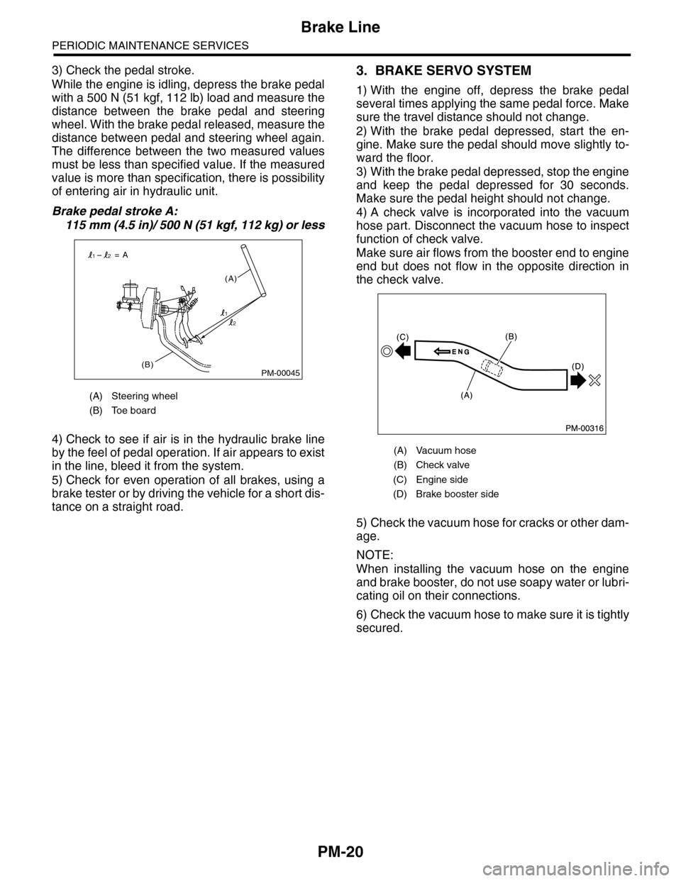
While the engine is idling, depress the brake pedal
with a 500 N (51 kgf, 112 lb) load and measure the
distance between the brake pedal and steering
wheel. With the brake pedal released, measure the
distance between pedal and steering wheel again.
The difference between the two measured values
must be less than specified value. If the measured
value is more than specification, there is possibility
of entering air in hydraulic unit.
Brake pedal stroke A:
115 mm (4.5 in)/ 500 N (51 kgf, 112 kg) or less
4) Check to see if air is in the hydraulic brake line
by the feel of pedal operation. If air appears to exist
in the line, bleed it from the system.
5) Check for even operation of all brakes, using a
brake tester or by driving the vehicle for a short dis-
tance on a straight road.
3. BRAKE SERVO SYSTEM
1) With the engine off, depress the brake pedal
several times applying the same pedal force. Make
sure the travel distance should not change.
2) With the brake pedal depressed, start the en-
gine. Make sure the pedal should move slightly to-
ward the floor.
3) With the brake pedal depressed, stop the engine
and keep the pedal depressed for 30 seconds.
Make sure the pedal height should not change.
4) A check valve is incorporated into the vacuum
hose part. Disconnect the vacuum hose to inspect
function of check valve.
Make sure air flows from the booster end to engine
end but does not flow in the opposite direction in
the check valve.
5) Check the vacuum hose for cracks or other dam-
age.
NOTE:
When installing the vacuum hose on the engine
and brake booster, do not use soapy water or lubri-
cating oil on their connections.
6) Check the vacuum hose to make sure it is tightly
secured.
(A) Steering wheel
(B) Toe board
PM-00045(B)
(A)
= A
1
12
2
(A) Vacuum hose
(B) Check valve
(C) Engine side
(D) Brake booster side
Page 2106 of 2453
5AT-90
Front Differential Assembly
AUTOMATIC TRANSMISSION
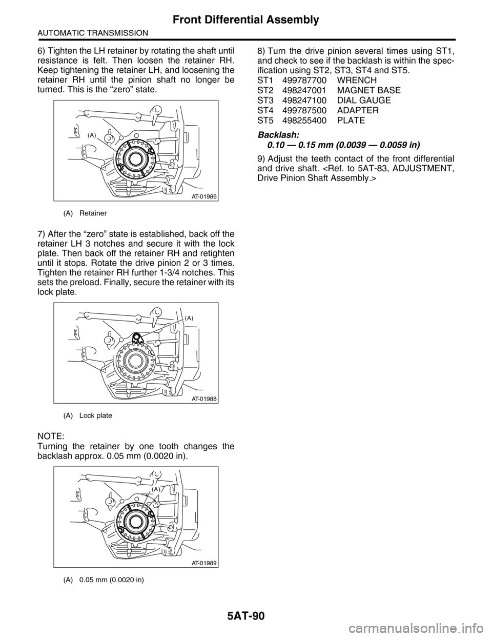
6) Tighten the LH retainer by rotating the shaft until
resistance is felt. Then loosen the retainer RH.
Keep tightening the retainer LH, and loosening the
retainer RH until the pinion shaft no longer be
turned. This is the “zero” state.
7) After the “zero” state is established, back off the
retainer LH 3 notches and secure it with the lock
plate. Then back off the retainer RH and retighten
until it stops. Rotate the drive pinion 2 or 3 times.
Tighten the retainer RH further 1-3/4 notches. This
sets the preload. Finally, secure the retainer with its
lock plate.
NOTE:
Turning the retainer by one tooth changes the
backlash approx. 0.05 mm (0.0020 in).
8) Turn the drive pinion several times using ST1,
and check to see if the backlash is within the spec-
ification using ST2, ST3, ST4 and ST5.
ST1 499787700 WRENCH
ST2 498247001 MAGNET BASE
ST3 498247100 DIAL GAUGE
ST4 499787500 ADAPTER
ST5 498255400 PLATE
Backlash:
0.10 — 0.15 mm (0.0039 — 0.0059 in)
9) Adjust the teeth contact of the front differential
and drive shaft.
(A) Retainer
(A) Lock plate
(A) 0.05 mm (0.0020 in)
AT-01986
(A)
AT-01988
(A)
AT-01989
(A)