2009 SUBARU TRIBECA change time
[x] Cancel search: change timePage 1687 of 2453
GD(H6DO)-75
Diagnostic Trouble Code (DTC) Detecting Criteria
GENERAL DESCRIPTION
AQ:DTC P0139 O2 SENSOR CIRCUIT SLOW RESPONSE (BANK 1 SENSOR 2)
1. OUTLINE OF DIAGNOSIS
Detect the slow response of the oxygen sensor.
Judge as NG if either the rich to lean response diagnosis or lean to rich response diagnosis is NG, and Judge
as OK if both are OK.
[Rich → Lean diagnosis response]
1. Measure the response time for oxygen sensor output changes when the A/F ratio changes to rich to lean.
If the measured response time is larger than the threshold value, it is NG. If it is smaller, it is OK.
2. Judge as NG when the oxygen sensor voltage is large (rich) when recovering from a deceleration fuel cut.
[Lean → Rich diagnosis response]
1. Measure the response time for oxygen sensor output changes when the A/F ratio changes to lean to rich.
If the measured response time is larger than the threshold value, it is NG.
2. Judge as NG when the oxygen sensor voltage remains small when recovering from a deceleration fuel cut.
Diagnostic method
Measure the response time of the output change of the oxygen sensor when the A/F ratio changes to rich to
lean. And Judge as NG when the measured response time is larger than the threshold value.
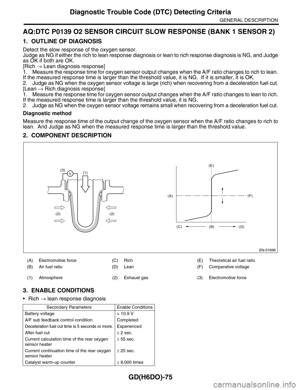
2. COMPONENT DESCRIPTION
3. ENABLE CONDITIONS
•Rich → lean response diagnosis
(A) Electromotive force (C) Rich (E) Theoretical air fuel ratio
(B) Air fuel ratio (D) Lean (F) Comparative voltage
(1) Atmosphere (2) Exhaust gas (3) Electromotive force
Secondary Parameters Enable Conditions
Battery voltage > 10.9 V
A/F sub feedback control condition Completed
Deceleration fuel cut time is 5 seconds or more. Experienced
After fuel cut≥ 2 sec.
Current calculation time of the rear oxygen
sensor heater
≥ 55 sec.
Current continuation time of the rear oxygen
sensor heater
≥ 25 sec.
Catalyst warm-up counter≥ 8,000 times
EN-01696
(3)V(1)
(2) (2)
(E)
(F)
(C) (B) (D)
(A)
Page 1688 of 2453
GD(H6DO)-76
Diagnostic Trouble Code (DTC) Detecting Criteria
GENERAL DESCRIPTION
4. GENERAL DRIVING CYCLE
Perform the diagnosis only once when deceleration fuel cut occurs after rapid acceleration. (Pay attention to
the oxygen sensor voltage for the timing of the deceleration.)
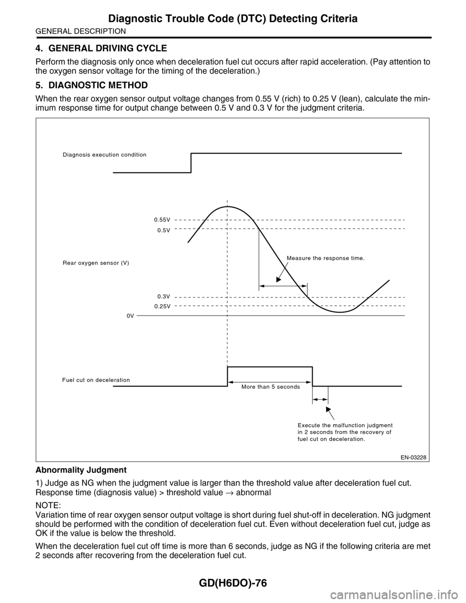
5. DIAGNOSTIC METHOD
When the rear oxygen sensor output voltage changes from 0.55 V (rich) to 0.25 V (lean), calculate the min-
imum response time for output change between 0.5 V and 0.3 V for the judgment criteria.
Abnormality Judgment
1) Judge as NG when the judgment value is larger than the threshold value after deceleration fuel cut.
Response time (diagnosis value) > threshold value → abnormal
NOTE:
Variation time of rear oxygen sensor output voltage is short during fuel shut-off in deceleration. NG judgment
should be performed with the condition of deceleration fuel cut. Even without deceleration fuel cut, judge as
OK if the value is below the threshold.
When the deceleration fuel cut off time is more than 6 seconds, judge as NG if the following criteria are met
2 seconds after recovering from the deceleration fuel cut.
0.55V
0.5V
0.3V
0.25V
0V
Diagnosis execution condition
Rear oxygen sensor (V)Measure the response time.
Fuel cut on decelerationMore than 5 seconds
Execute the malfunction judgment in 2 seconds from the recovery of fuel cut on deceleration.
EN-03228
Page 1689 of 2453
GD(H6DO)-77
Diagnostic Trouble Code (DTC) Detecting Criteria
GENERAL DESCRIPTION
2) Judge as NG when the oxygen sensor voltage at recovery from a deceleration fuel cut, is large.
If the fuel cut time in a deceleration fuel cut is long (more than 6 s), and even after recovering from a decel-
eration fuel cut, the oxygen sensor voltage is high (0.55 V or more), judge as NG.
Time Needed for Diagnosis: 1 time
Malfunction Indicator Light Illumination: Illuminates when malfunctions occur in 2 continuous driving cy-
cles.
Normality Judgment
1) Regardless of a deceleration fuel cut, if the response time (diagnosis value) when the oxygen sensor volt-
age has changed from rich to lean is shorter than the threshold value (judgment value), judge as a normal
condition.
Response time (diagnosis value) ≤ threshold value → normal
2) Do not judge as a normal condition.
Judge as OK when the criteria below are met.
6. DTC CLEAR CONDITION
•When the OK idling cycle is completed 40 times in a row
•When “Clear Memory” is performed
7. MALFUNCTION INDICATOR LIGHT CLEAR CONDITIONS
•When the OK driving cycle is completed 3 times in a row
•When “Clear Memory” is performed
8. FAIL SAFE
Sub feedback control: Not allowed
9. ECM OPERATION AT DTC SETTING
•Memorize the freeze frame data. (For test mode $02)
•Memorize the diagnostic value and trouble standard value. (For test mode $06)
10.ENABLE CONDITIONS
•Lean → rich response diagnosis
11.GENERAL DRIVING CYCLE
Perform the diagnosis only once when deceleration fuel cut occurs after rapid acceleration. (Pay attention to
the oxygen sensor voltage for the timing of the deceleration.)
Judgment Value
Malfunction Criteria Threshold Value
Shortest time change from rich (500 mV
O2 output) to lean (300 mV) if voltage
reduces from 550 mV to 250 mV.
> 0.327 sec.
or
Longest time over 550 mV > 2 sec.
Judgment Value
Malfunction Criteria Threshold Value
Shortest time change from rich (500 mV
O2 output) to lean (300 mV) if voltage
reduces from 550 mV to 250 mV.
≤ 0.327 sec.
Secondary Parameters Enable Conditions
Battery voltage > 10.9 V
A/F main feedback control condition Complete
5 seconds or more deceleration fuel cut. Experienced
After fuel cut≥ 2 sec.
Page 1690 of 2453
GD(H6DO)-78
Diagnostic Trouble Code (DTC) Detecting Criteria
GENERAL DESCRIPTION
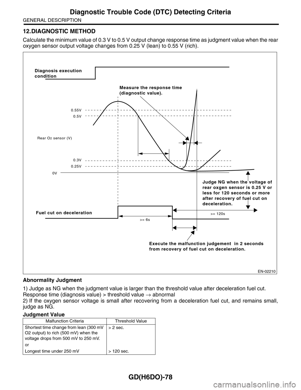
12.DIAGNOSTIC METHOD
Calculate the minimum value of 0.3 V to 0.5 V output ch a n g e r e s p on s e t im e a s ju d g m e n t v a lu e w h en th e re a r
oxygen sensor output voltage changes from 0.25 V (lean) to 0.55 V (rich).
Abnormality Judgment
1) Judge as NG when the judgment value is larger than the threshold value after deceleration fuel cut.
Response time (diagnosis value) > threshold value → abnormal
2) If the oxygen sensor voltage is small after recovering from a deceleration fuel cut, and remains small,
judge as NG.
Judgment Value
Malfunction Criteria Threshold Value
Shortest time change from lean (300 mV
O2 output) to rich (500 mV) when the
voltage drops from 500 mV to 250 mV.
> 2 sec.
or
Longest time under 250 mV > 120 sec.
EN-02210
Fuel cut on deceleration
Execute the malfunction judgement in 2 seconds
from recovery of fuel cut on deceleration.
Rear O2 sensor (V)
0V
>= 6s
>= 120s
0.25V
0.3V
0.5V
0.55V
Measure the response time
(diagnostic value).
Diagnosis execution
condition
Judge NG when the voltage of
rear oxgen sensor is 0.25 V or
less for 120 seconds or more
after recovery of fuel cut on
deceleration.
Page 1691 of 2453
GD(H6DO)-79
Diagnostic Trouble Code (DTC) Detecting Criteria
GENERAL DESCRIPTION
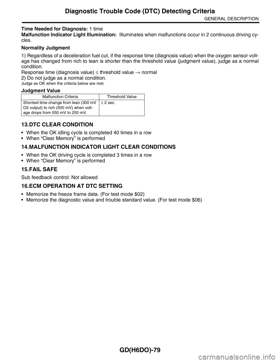
Time Needed for Diagnosis: 1 time
Malfunction Indicator Light Illumination: Illuminates when malfunctions occur in 2 continuous driving cy-
cles.
Normality Judgment
1) Regardless of a deceleration fuel cut, if the response time (diagnosis value) when the oxygen sensor volt-
age has changed from rich to lean is shorter than the threshold value (judgment value), judge as a normal
condition.
Response time (diagnosis value) ≤ threshold value → normal
2) Do not judge as a normal condition.
Judge as OK when the criteria below are met.
13.DTC CLEAR CONDITION
•When the OK idling cycle is completed 40 times in a row
•When “Clear Memory” is performed
14.MALFUNCTION INDICATOR LIGHT CLEAR CONDITIONS
•When the OK driving cycle is completed 3 times in a row
•When “Clear Memory” is performed
15.FAIL SAFE
Sub feedback control: Not allowed
16.ECM OPERATION AT DTC SETTING
•Memorize the freeze frame data. (For test mode $02)
•Memorize the diagnostic value and trouble standard value. (For test mode $06)
Judgment Value
Malfunction Criteria Threshold Value
Shortest time change from lean (300 mV
O2 output) to rich (500 mV) when volt-
age drops from 550 mV to 250 mV.
≤ 2 sec.
Page 1716 of 2453
GD(H6DO)-104
Diagnostic Trouble Code (DTC) Detecting Criteria
GENERAL DESCRIPTION
BN:DTC P0301 CYLINDER 1 MISFIRE DETECTED
1. OUTLINE OF DIAGNOSIS
Detect the presence of misfire occurrence. (Revolution fluctuation method)
Monitoring Misfire which influences exhaust deterioration (1.5 times of FTP) and catalyst damage is made
obligatory by the law. Misfire affecting these two has three patterns below. Intermittent misfire (Different cyl-
inders misfire intermittently.):
•Intermittent misfire (The same cylinder misfires in random, or different cylinders misfire in random.): FTP
1.5 times misfire
•Every time misfire (The same cylinder misfires every time.): FTP 1.5 times misfire, Catalyst damage misfire
The following detecting methods are adopted for these detection.
1) Intermittent misfire: FTP 1.5 times misfire
•120° Interval Difference Method
•360° Interval Difference Method (whole range)
•720° Interval Difference Method (3,000 rpm or less)
2) Misfire every time: FTP 1.5 times misfire, Catalyst damage misfire
•360° Interval Difference Method
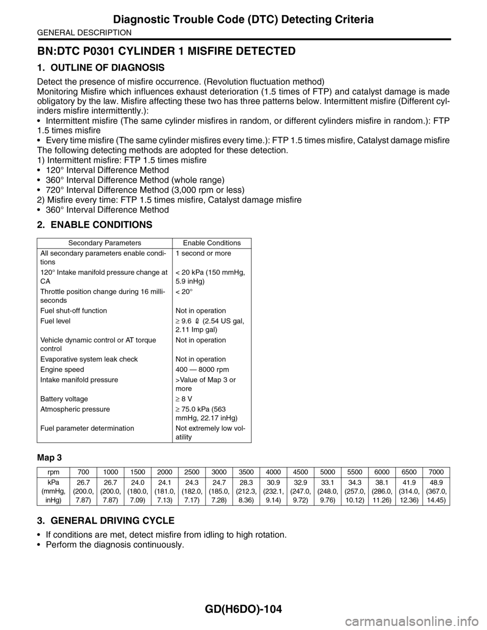
2. ENABLE CONDITIONS
Map 3
3. GENERAL DRIVING CYCLE
•If conditions are met, detect misfire from idling to high rotation.
•Perform the diagnosis continuously.
Secondary Parameters Enable Conditions
All secondary parameters enable condi-
tions
1 second or more
120° Intake manifold pressure change at
CA
< 20 kPa (150 mmHg,
5.9 inHg)
Throttle position change during 16 milli-
seconds
< 20°
Fuel shut-off function Not in operation
Fuel level≥ 9.6 2 (2.54 US gal,
2.11 Imp gal)
Ve h i c l e d y n a m i c c o n t r o l o r AT t o r q u e
control
Not in operation
Evaporative system leak check Not in operation
Engine speed 400 — 8000 rpm
Intake manifold pressure >Value of Map 3 or
more
Battery voltage≥ 8 V
Atmospheric pressure≥ 75.0 kPa (563
mmHg, 22.17 inHg)
Fuel parameter determination Not extremely low vol-
atility
rpm 700 1000 1500 2000 2500 3000 3500 4000 4500 5000 5500 6000 6500 7000
kPa
(mmHg,
inHg)
26.7
(200.0,
7.87)
26.7
(200.0,
7.87)
24.0
(180.0,
7.09)
24.1
(181.0,
7.13)
24.3
(182.0,
7.17)
24.7
(185.0,
7.28)
28.3
(212.3,
8.36)
30.9
(232.1,
9.14)
32.9
(247.0,
9.72)
33.1
(248.0,
9.76)
34.3
(257.0,
10.12)
38.1
(286.0,
11.26)
41.9
(314.0,
12.36)
48.9
(367.0,
14.45)
Page 1717 of 2453
GD(H6DO)-105
Diagnostic Trouble Code (DTC) Detecting Criteria
GENERAL DESCRIPTION
4. DIAGNOSTIC METHOD
When a misfire occurs, the engine RPM will decreased and the crankshaft position speed will change. Cal-
culate the interval difference value (diagnostic value) from crankshaft position speed by the following formu-
la, and judge whether a misfire is occurring or not comparing the calculated result with judgment value.
Counting the number of misfires, if the misfire ratio is higher during 1000 rev. or 200 rev. Judge correspond-
ing cylinders as NG.
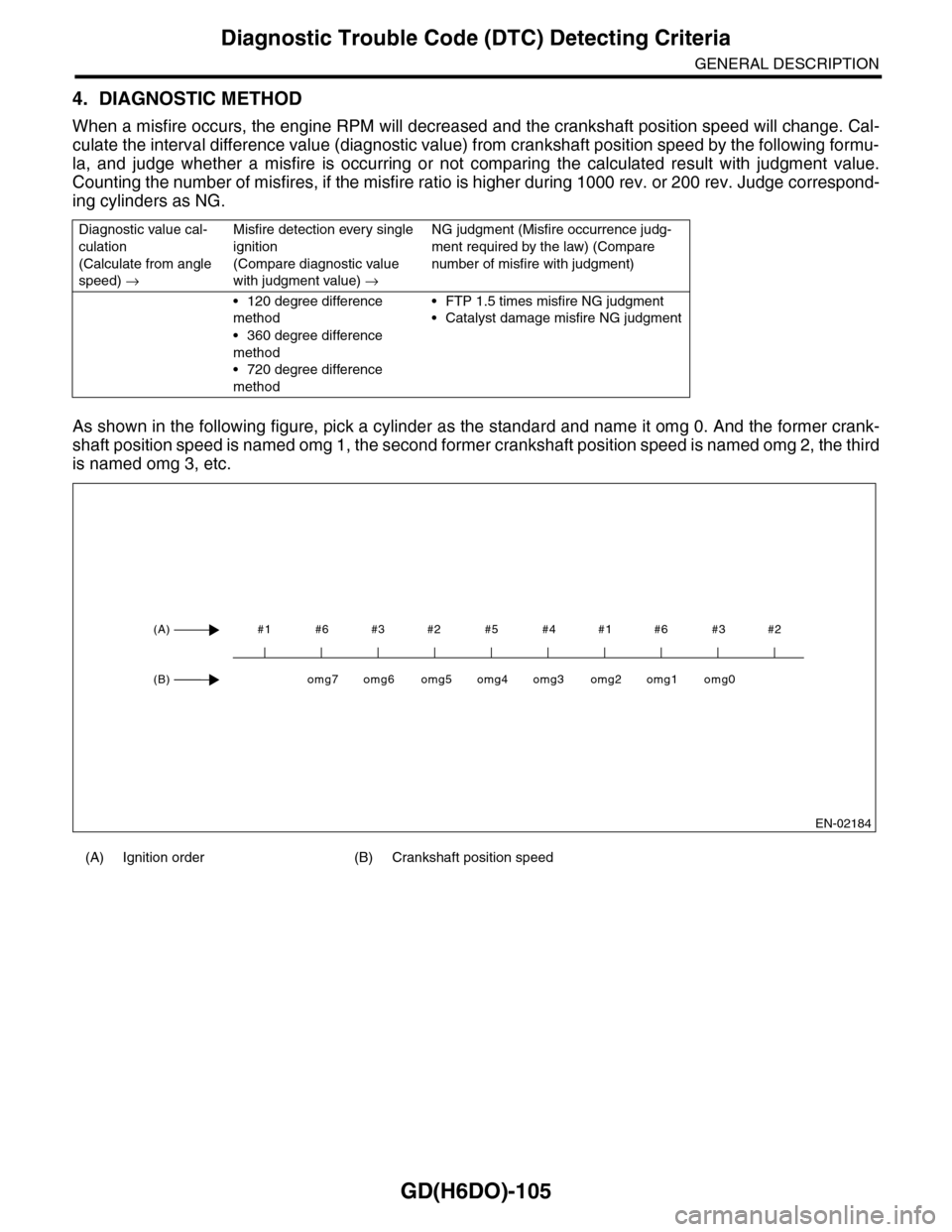
As shown in the following figure, pick a cylinder as the standard and name it omg 0. And the former crank-
shaft position speed is named omg 1, the second former crankshaft position speed is named omg 2, the third
is named omg 3, etc.
Diagnostic value cal-
culation
(Calculate from angle
speed) →
Misfire detection every single
ignition
(Compare diagnostic value
with judgment value) →
NG judgment (Misfire occurrence judg-
ment required by the law) (Compare
number of misfire with judgment)
•120 degree difference
method
•360 degree difference
method
•720 degree difference
method
•FTP 1.5 times misfire NG judgment
•Catalyst damage misfire NG judgment
(A) Ignition order (B) Crankshaft position speed
EN-02184
#1 #6 #3 #2 #5 #4 #1 #6 #3 #2(A)
(B)omg0omg1omg2omg3omg4omg5omg6omg7
Page 1733 of 2453
GD(H6DO)-121
Diagnostic Trouble Code (DTC) Detecting Criteria
GENERAL DESCRIPTION
CB:DTC P0420 CATALYST SYSTEM EFFICIENCY BELOW THRESHOLD (BANK 1)
1. OUTLINE OF DIAGNOSIS
Detect the deterioration of the catalyst function.
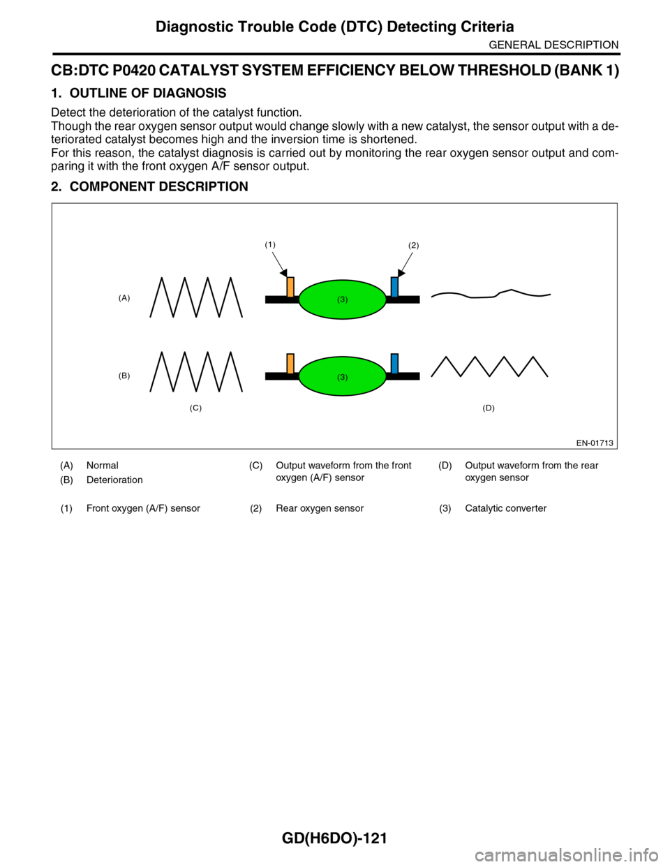
Though the rear oxygen sensor output would change slowly with a new catalyst, the sensor output with a de-
teriorated catalyst becomes high and the inversion time is shortened.
For this reason, the catalyst diagnosis is carried out by monitoring the rear oxygen sensor output and com-
paring it with the front oxygen A/F sensor output.
2. COMPONENT DESCRIPTION
(A) Normal (C) Output waveform from the front
oxygen (A/F) sensor
(D) Output waveform from the rear
oxygen sensor(B) Deterioration
(1) Front oxygen (A/F) sensor (2) Rear oxygen sensor (3) Catalytic converter
EN-01713
(A)
(B)
(C)(D)
(1)(2)
(3)
(3)