Page 2070 of 2453
5AT-54
Control Valve Body
AUTOMATIC TRANSMISSION
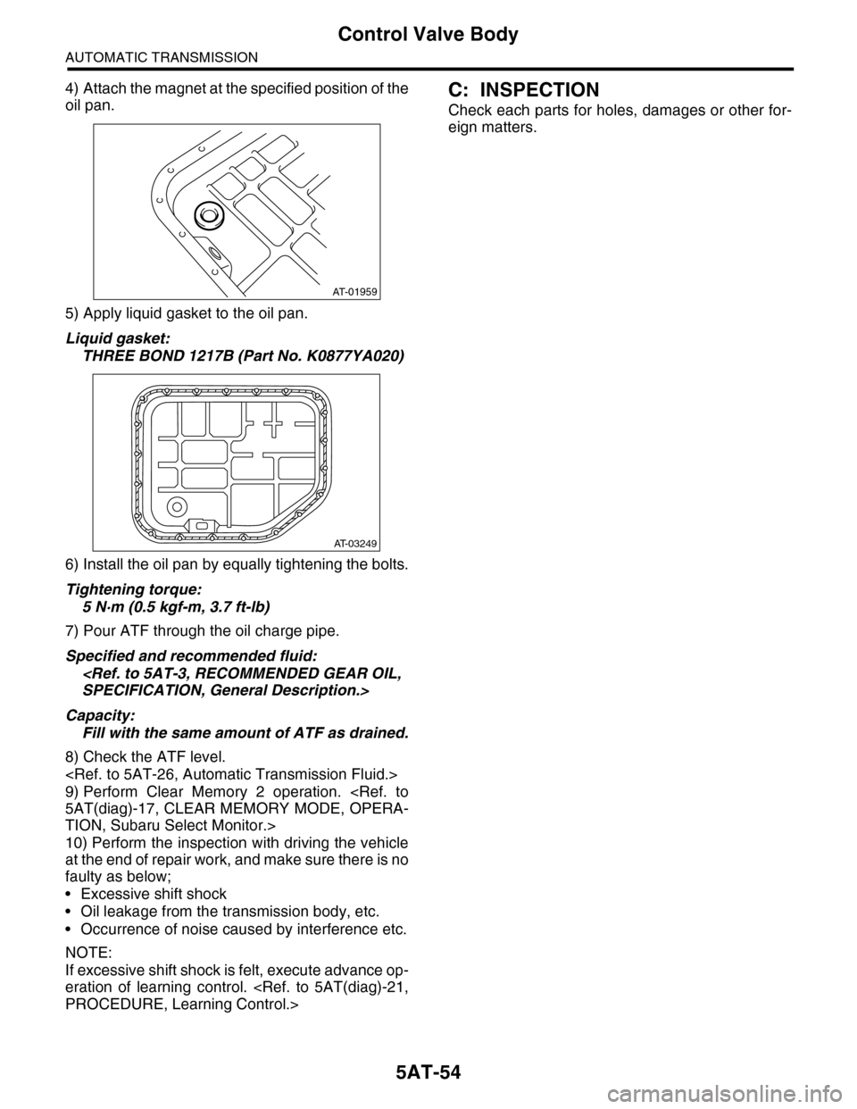
4) Attach the magnet at the specified position of the
oil pan.
5) Apply liquid gasket to the oil pan.
Liquid gasket:
THREE BOND 1217B (Part No. K0877YA020)
6) Install the oil pan by equally tightening the bolts.
Tightening torque:
5 N·m (0.5 kgf-m, 3.7 ft-lb)
7) Pour ATF through the oil charge pipe.
Specified and recommended fluid:
SPECIFICATION, General Description.>
Capacity:
Fill with the same amount of ATF as drained.
8) Check the ATF level.
9) Perform Clear Memory 2 operation.
5AT(diag)-17, CLEAR MEMORY MODE, OPERA-
TION, Subaru Select Monitor.>
10) Perform the inspection with driving the vehicle
at the end of repair work, and make sure there is no
faulty as below;
•Excessive shift shock
•Oil leakage from the transmission body, etc.
•Occurrence of noise caused by interference etc.
NOTE:
If excessive shift shock is felt, execute advance op-
eration of learning control.
PROCEDURE, Learning Control.>
C: INSPECTION
Check each parts for holes, damages or other for-
eign matters.
AT-01959
AT-03249
Page 2072 of 2453
5AT-56
Transmission Control Module (TCM)
AUTOMATIC TRANSMISSION
19.Transmission Control Mod-
ule (TCM)
A: REMOVAL
1) Disconnect the ground cable from battery.
2) Remove the lower cover and then disconnect
the connector.
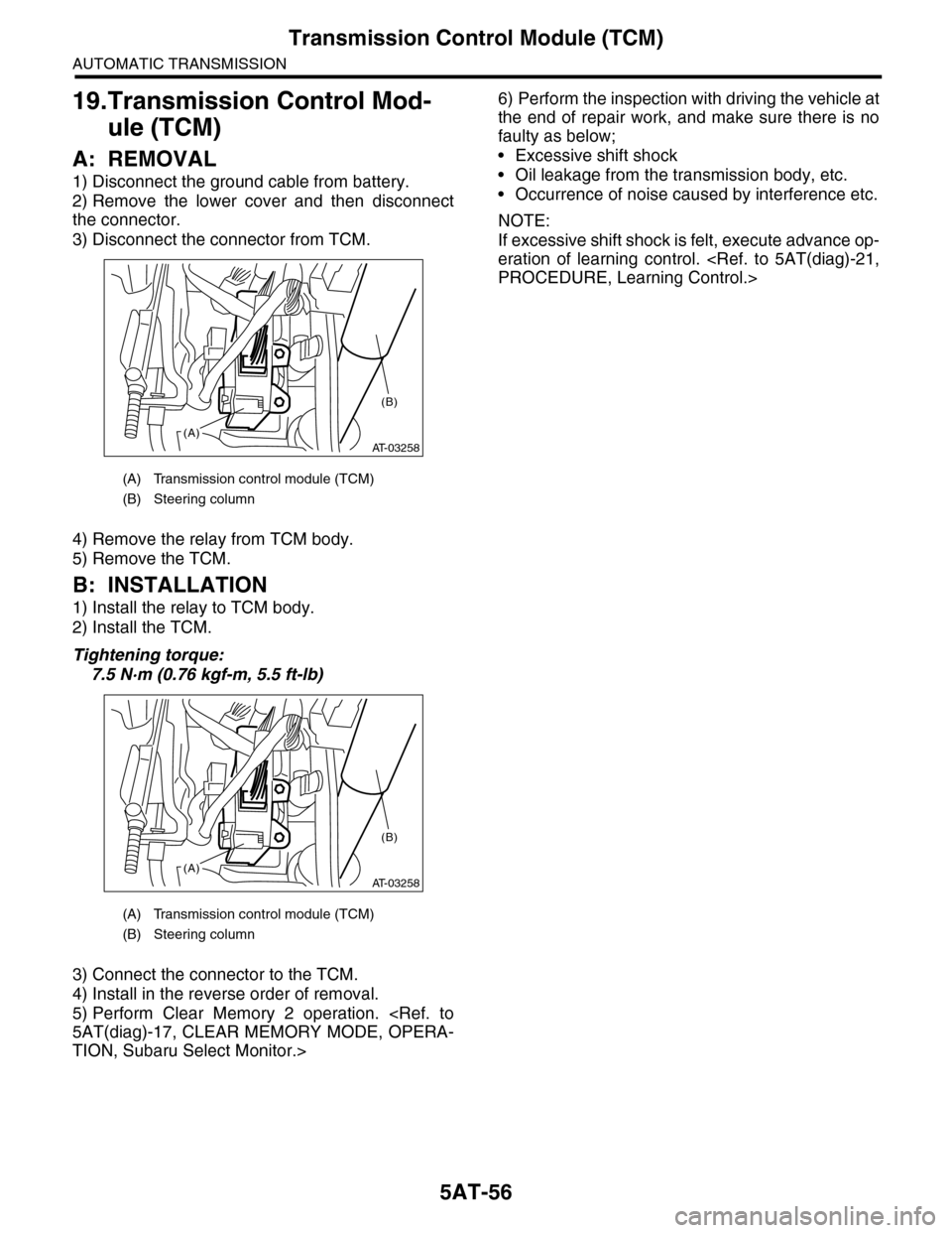
3) Disconnect the connector from TCM.
4) Remove the relay from TCM body.
5) Remove the TCM.
B: INSTALLATION
1) Install the relay to TCM body.
2) Install the TCM.
Tightening torque:
7.5 N·m (0.76 kgf-m, 5.5 ft-lb)
3) Connect the connector to the TCM.
4) Install in the reverse order of removal.
5) Perform Clear Memory 2 operation.
5AT(diag)-17, CLEAR MEMORY MODE, OPERA-
TION, Subaru Select Monitor.>
6) Perform the inspection with driving the vehicle at
the end of repair work, and make sure there is no
faulty as below;
•Excessive shift shock
•Oil leakage from the transmission body, etc.
•Occurrence of noise caused by interference etc.
NOTE:
If excessive shift shock is felt, execute advance op-
eration of learning control.
PROCEDURE, Learning Control.>
(A) Transmission control module (TCM)
(B) Steering column
(A) Transmission control module (TCM)
(B) Steering column
AT-03258(A)
(B)
AT-03258(A)
(B)
Page 2073 of 2453
5AT-57
ATF Cooler Pipe & Hose
AUTOMATIC TRANSMISSION
20.ATF Cooler Pipe & Hose
A: REMOVAL
1) Set the vehicle on a lift.
2) Lift-up the vehicle.
3) Remove the under cover.
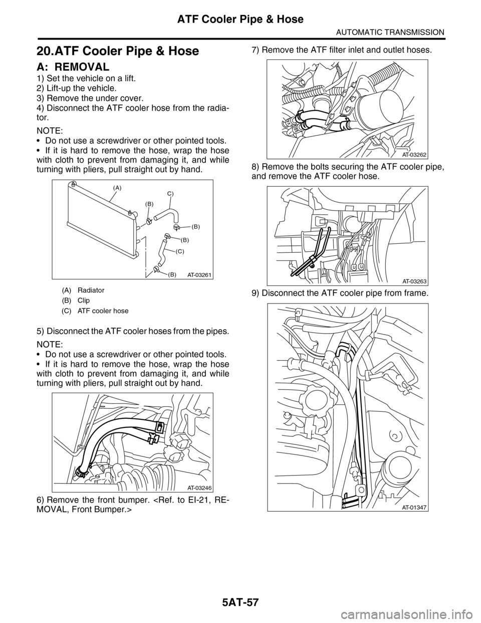
4) Disconnect the ATF cooler hose from the radia-
tor.
NOTE:
•Do not use a screwdriver or other pointed tools.
•If it is hard to remove the hose, wrap the hose
with cloth to prevent from damaging it, and while
turning with pliers, pull straight out by hand.
5) Disconnect the ATF cooler hoses from the pipes.
NOTE:
•Do not use a screwdriver or other pointed tools.
•If it is hard to remove the hose, wrap the hose
with cloth to prevent from damaging it, and while
turning with pliers, pull straight out by hand.
6) Remove the front bumper.
MOVAL, Front Bumper.>
7) Remove the ATF filter inlet and outlet hoses.
8) Remove the bolts securing the ATF cooler pipe,
and remove the ATF cooler hose.
9) Disconnect the ATF cooler pipe from frame.(A) Radiator
(B) Clip
(C) ATF cooler hose
AT-03261
(A)
(B)
C)
(C)
(B)
(B)
(B)
AT-03246
AT-03262
AT-03263
AT-01347
Page 2074 of 2453
5AT-58
ATF Cooler Pipe & Hose
AUTOMATIC TRANSMISSION
10) Remove the oil cooler inlet and outlet pipes.
NOTE:
When disconnecting the outlet pipe, be careful not
to lose the ball and spring used with retaining
screw.
B: INSTALLATION
1) Install the oil cooler inlet and outlet pipes with
new washer.
Tightening torque:
T1: 40 N·m (4.1 kgf-m, 29.5 ft-lb)
T2: 41 N·m (4.2 kgf-m, 30.4 ft-lb)
T3: 45 N·m (4.6 kgf-m, 33.2 ft-lb)
2) Install the ATF cooler pipe to frame.
3) Attach the bolts securing the ATF cooler pipe,
and attach the ATF cooler hose.
4) Attach the ATF filter inlet and outlet hoses.
5) Install the front bumper.
LATION, Front Bumper.>
(A) Outlet pipe
(B) Inlet pipe
AT-01383
(A)
(B)
AT-03133
T2
T1 T2
T3
AT-01347
AT-03263
AT-03262
Page 2078 of 2453
5AT-62
Torque Converter Assembly
AUTOMATIC TRANSMISSION
23.Torque Converter Assembly
A: REMOVAL
1) Remove the transmission assembly from vehicle
body.
Transmission Assembly.>
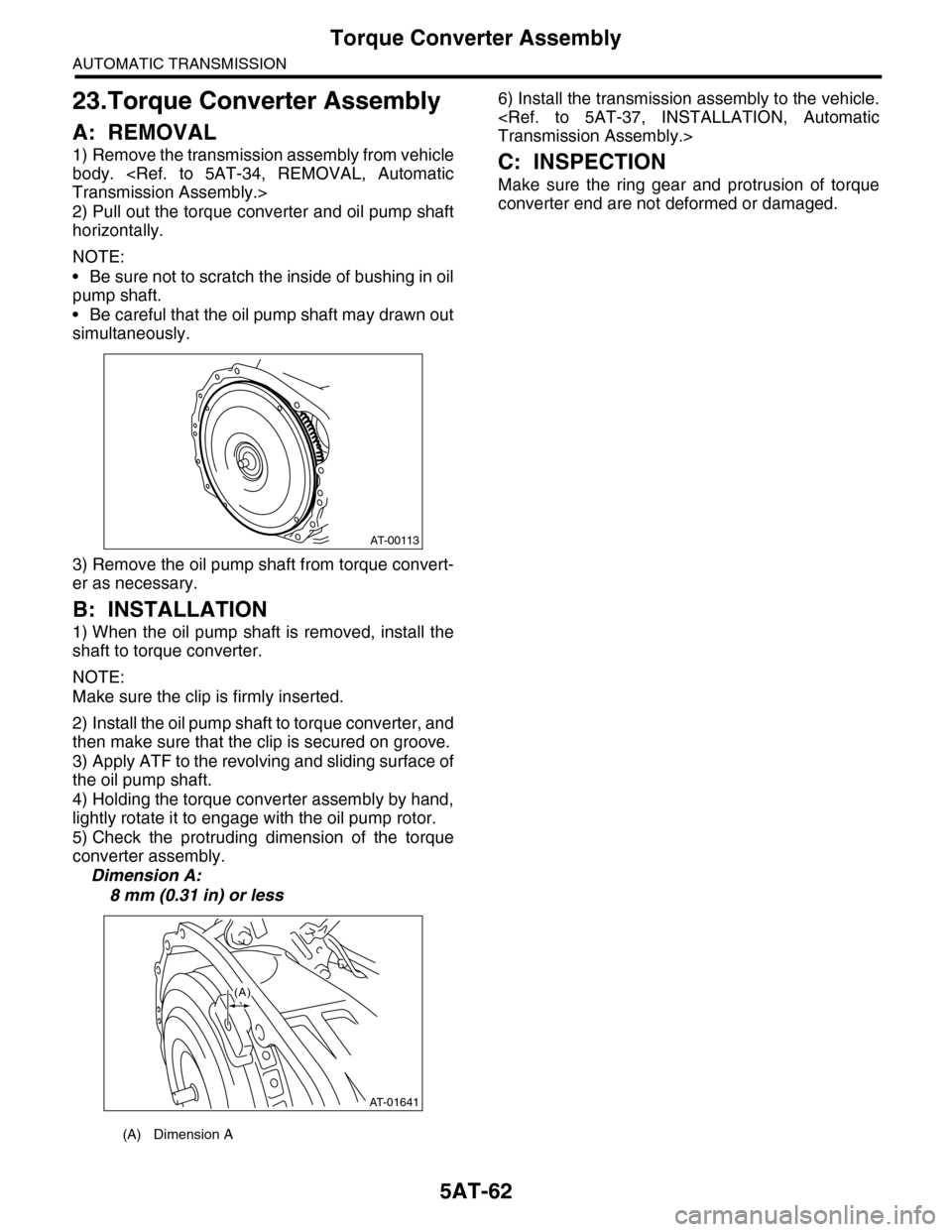
2) Pull out the torque converter and oil pump shaft
horizontally.
NOTE:
•Be sure not to scratch the inside of bushing in oil
pump shaft.
•Be careful that the oil pump shaft may drawn out
simultaneously.
3) Remove the oil pump shaft from torque convert-
er as necessary.
B: INSTALLATION
1) When the oil pump shaft is removed, install the
shaft to torque converter.
NOTE:
Make sure the clip is firmly inserted.
2) Install the oil pump shaft to torque converter, and
then make sure that the clip is secured on groove.
3) Apply ATF to the revolving and sliding surface of
the oil pump shaft.
4) Holding the torque converter assembly by hand,
lightly rotate it to engage with the oil pump rotor.
5) Check the protruding dimension of the torque
converter assembly.
Dimension A:
8 mm (0.31 in) or less
6) Install the transmission assembly to the vehicle.
Transmission Assembly.>
C: INSPECTION
Make sure the ring gear and protrusion of torque
converter end are not deformed or damaged.
(A) Dimension A
AT-00113
AT-01641
(A)
Page 2093 of 2453
5AT-77
Oil Pump Cover
AUTOMATIC TRANSMISSION
31.Oil Pump Cover
A: REMOVAL
1) Remove the transmission assembly from vehicle
body.
Transmission Assembly.>
2) Pull out the torque converter assembly.
5AT-62, REMOVAL, Torque Converter Assembly.>
3) Remove the transmission harness connector
from stay.
4) Remove the oil charge pipe.
REMOVAL, Oil Charge Pipe.>
5) Remove the ATF filter inlet and outlet pipes.
Hose.>
6) Separate the converter case and transmission
case.
Case.>
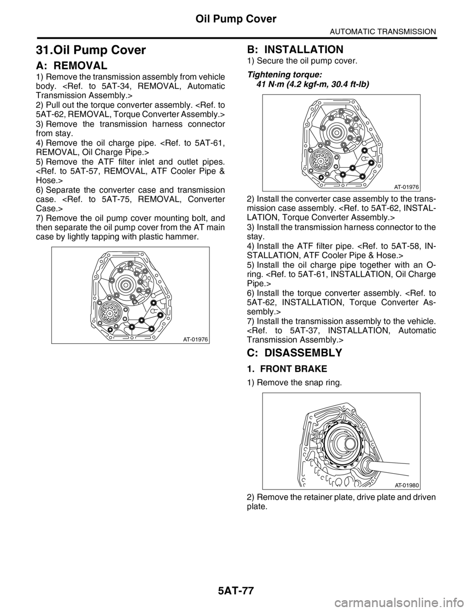
7) Remove the oil pump cover mounting bolt, and
then separate the oil pump cover from the AT main
case by lightly tapping with plastic hammer.
B: INSTALLATION
1) Secure the oil pump cover.
Tightening torque:
41 N·m (4.2 kgf-m, 30.4 ft-lb)
2) Install the converter case assembly to the trans-
mission case assembly.
LATION, Torque Converter Assembly.>
3) Install the transmission harness connector to the
stay.
4) Install the ATF filter pipe.
STALLATION, ATF Cooler Pipe & Hose.>
5) Install the oil charge pipe together with an O-
ring.
Pipe.>
6) Install the torque converter assembly.
5AT-62, INSTALLATION, Torque Converter As-
sembly.>
7) Install the transmission assembly to the vehicle.
Transmission Assembly.>
C: DISASSEMBLY
1. FRONT BRAKE
1) Remove the snap ring.
2) Remove the retainer plate, drive plate and driven
plate.
AT-01976
AT-01976
AT-01980
Page 2099 of 2453
5AT-83
Drive Pinion Shaft Assembly
AUTOMATIC TRANSMISSION
7) Measure dimension “B” of the drive pinion shaft
ST 398643600 GAUGE
8) Calculate the thickness “t” (mm) of the drive pin-
ion shim.
t = 6.5 ± 0.0625 – (B – A)
9) Select three or less shims from following table.
E: INSPECTION
•Make sure that all component parts are free of
scratches, holes and other faults.
•Adjust the tooth alignment.
JUSTMENT, Drive Pinion Shaft Assembly.>
F: ADJUSTMENT
1) Remove the liquid gasket from the mating sur-
face completely.
2) Install the converter case to oil pump cover, and
secure them with tightening four bolts evenly.
NOTE:
Use an old gasket or aluminum washer to prevent
damaging the mating surface of the housing.
Tightening torque:
41 N·m (4.2 kgf-m, 30.4 ft-lb)
3) Rotate the drive pinion a few times using ST1
and ST2.
ST1 18667AA010 HOLDER
ST2 499787700 WRENCH
4) Adjust the drive pinion and hypoid driven gear
backlash.
Differential Assembly.>
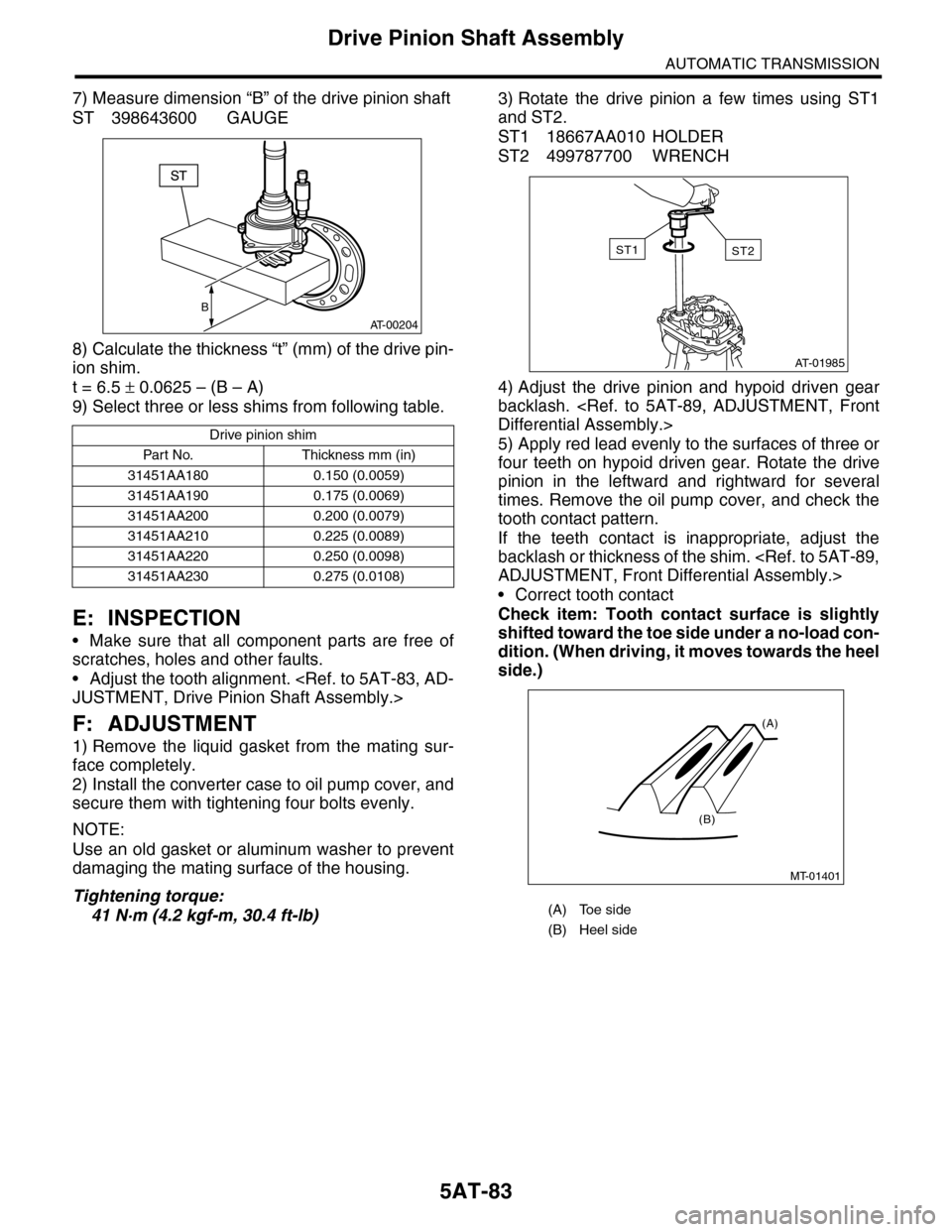
5) Apply red lead evenly to the surfaces of three or
four teeth on hypoid driven gear. Rotate the drive
pinion in the leftward and rightward for several
times. Remove the oil pump cover, and check the
tooth contact pattern.
If the teeth contact is inappropriate, adjust the
backlash or thickness of the shim.
ADJUSTMENT, Front Differential Assembly.>
•Correct tooth contact
Check item: Tooth contact surface is slightly
shifted toward the toe side under a no-load con-
dition. (When driving, it moves towards the heel
side.)
Drive pinion shim
Par t No. Thickness mm (in)
31451AA180 0.150 (0.0059)
31451AA190 0.175 (0.0069)
31451AA200 0.200 (0.0079)
31451AA210 0.225 (0.0089)
31451AA220 0.250 (0.0098)
31451AA230 0.275 (0.0108)
B
AT-00204
(A) Toe side
(B) Heel side
AT-01985
ST2ST1
MT-01401
(A)
(B)
Page 2103 of 2453
5AT-87
Front Differential Assembly
AUTOMATIC TRANSMISSION
2) Secure the case in a vise, remove the hypoid
driven gear tightening bolts, and then separate the
hypoid driven gear into case (RH) and case (LH).
3) Pull out the straight pin and shaft, and then re-
move the differential bevel gear, washer and differ-
ential bevel pinion.
2. SIDE RETAINER
NOTE:
After adjusting the drive pinion backlash and tooth
contact, remove and install the oil seal and O-ring.
1) Remove the O-ring.
2) Remove the oil seal.
3) Remove the split pin, and then remove the claw.
ST 398527700 PULLER
4) Attach two claws to the outer race, and set the
ST to side retainer.
ST 398527700 PULLER
5) Restore the removed claws to original position,
and install the pin and split pin.
(A) Hypoid driven gear
(B) Differential case (RH)
(C) Differential case (LH)
(A) Differential case (RH)
(B)
AT-00217
(A)
(C)
AT-00218(A)
AT-00219
(A) Claw
(B) Split pin
(C) Pin
(A) Shaft
(B) Claw
AT-00220
AT-00221
AT-00222