Page 1958 of 2453
SP(H6DO)-3
Accelerator Pedal
SPEED CONTROL SYSTEMS
2. Accelerator Pedal
A: REMOVAL
1) Disconnect the ground cable from battery.
2) Disconnect the connector.
3) Remove the nut securing accelerator pedal as-
sembly.
B: INSTALLATION
Install in the reverse order of removal.
Tightening torque:
7.5 N·m (0.76 kgf-m, 5.5 ft-lb)
C: DISASSEMBLY
NOTE:
The accelerator pedal cannot be disassembled.
SP-02035
Page 1978 of 2453
SC(H6DO)-20
Generator
STARTING/CHARGING SYSTEMS
CAUTION:
When holding the rotor with a vise, place alumi-
num plates or wooden pieces on the vise jaws
to prevent rotor from damage.
5) Remove the ball bearing as follows.
(1) Remove the bolt, and then remove the bear-
ing retainer.
(2) Firmly install an appropriate tool (such as a
fit socket wrench) to bearing inner race.
(3) Push the ball bearing off the front cover us-
ing a press.
6) Remove the bearing from rotor using a bearing
puller.
7) Separate the connection between rectifier and
stator coil to remove stator coil.
CAUTION:
Do not allow a 180 — 270 W soldering iron to
contact the terminals for more than 5 seconds
at once because the rectifier cannot withstand
so much heat.
8) Remove the IC regulator as follows.
(1) Remove the screws which secure IC regula-
tor to rear cover.
(A) Front cover
(B) Pulley
(C) Nut
(D) Rotor
(A)
(B)
(C)
(D)SC-00036
SC-00081
SC-00082
SC-00046
SC-00083
SC-00084
Page 1979 of 2453
SC(H6DO)-21
Generator
STARTING/CHARGING SYSTEMS
(2) Unsolder the connection between IC regula-
tor and rectifier to remove IC regulator.
9) Remove the brush as follows.
(1) Remove the cover A.
(2) Remove the cover B.
(3) Separate the brush from connection to re-
move.
10) Remove the rectifier as follows.
(1) Remove the bolts which secure rectifier.
(2) Remove the cover of terminal B.
(3) Remove the nut of terminal B, and then re-
move the rectifier.(A) Cover A
(A) Cover B
SC-00085
SC-00086
(A)
SC-00087
(A)
SC-00088
SC-00089
SC-00090
SC-00091
Page 1980 of 2453

SC(H6DO)-22
Generator
STARTING/CHARGING SYSTEMS
D: ASSEMBLY
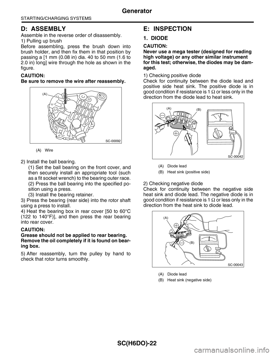
Assemble in the reverse order of disassembly.
1) Pulling up brush
Before assembling, press the brush down into
brush holder, and then fix them in that position by
passing a [1 mm (0.08 in) dia. 40 to 50 mm (1.6 to
2.0 in) long] wire through the hole as shown in the
figure.
CAUTION:
Be sure to remove the wire after reassembly.
2) Install the ball bearing.
(1) Set the ball bearing on the front cover, and
then securely install an appropriate tool (such
as a fit socket wrench) to the bearing outer race.
(2) Press the ball bearing into the specified po-
sition using a press.
(3) Install the bearing retainer.
3) Press the bearing (rear side) into the rotor shaft
using a press to install.
4) Heat the bearing box in rear cover [50 to 60°C
(122 to 140°F)], and then press the rear bearing
into rear cover.
CAUTION:
Grease should not be applied to rear bearing.
Remove the oil completely if it is found on bear-
ing box.
5) After reassembly, turn the pulley by hand to
check that rotor turns smoothly.
E: INSPECTION
1. DIODE
CAUTION:
Never use a mega tester (designed for reading
high voltage) or any other similar instrument
for this test; otherwise, the diodes may be dam-
aged.
1) Checking positive diode
Check for continuity between the diode lead and
positive side heat sink. The positive diode is in
good condition if resistance is 1 Ω o r l e s s o n l y i n t h e
direction from the diode lead to heat sink.
2) Checking negative diode
Check for continuity between the negative side
heat sink and diode lead. The negative diode is in
good condition if resistance is 1 Ω o r l e s s o n l y i n t h e
direction from the heat sink to diode lead.
(A) Wire
SC-00092
(A)
(A) Diode lead
(B) Heat sink (positive side)
(A) Diode lead
(B) Heat sink (negative side)
SC-00042
(B)(A)
(A)
(B)
SC-00043
Page 1992 of 2453
PM-9
Spark Plug
PERIODIC MAINTENANCE SERVICES
5. Spark Plug
A: REPLACEMENT
1) Remove the battery and battery carrier.
2) Remove the air cleaner case.
3) Detach the connector from ignition coil.
4) Remove the ignition coil.
5) Remove the spark plug with a spark plug socket.
6) Tighten the new spark plug lightly with hand, and
then secure with a spark plug socket to the speci-
fied torque.
Recommended spark plug:
NGK: ILFR6B
Tightening torque:
21 N·m (2.1 kgf-m, 15.2 ft-lb)
7) Tighten the ignition coil.
Tightening torque:
16 N·m (1.6 kgf-m, 11.7 ft-lb)
NOTE:
•Be sure to place the gasket between the cylinder
head and spark plug.
•If the torque wrench is not available, tighten the
spark plug until gasket contacts cylinder head; then
tighten further 1/4 to 1/2 turns.
(A) Bracket
(B) Connector
IG-02004(B)
(A)
PM-00112
Page 1997 of 2453

PM-14
Engine Coolant
PERIODIC MAINTENANCE SERVICES
10.Engine Coolant
A: REPLACEMENT
1. REPLACEMENT OF ENGINE COOLANT
WARNING:
The radiator is of the pressurized type. Do not
attempt to open the radiator cap immediately
after the engine has been stopped.
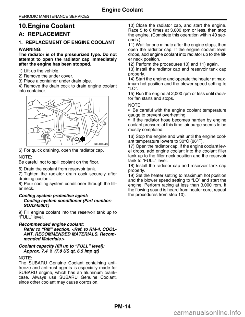
1) Lift-up the vehicle.
2) Remove the under cover.
3) Place a container under drain pipe.
4) Remove the drain cock to drain engine coolant
into container.
5) For quick draining, open the radiator cap.
NOTE:
Be careful not to spill coolant on the floor.
6) Drain the coolant from reservoir tank.
7) Tighten the radiator drain cock securely after
draining coolant.
8) Pour cooling system conditioner through the fill-
er neck.
Cooling system protective agent:
Cooling system conditioner (Part number:
SOA345001)
9) Fill engine coolant into the reservoir tank up to
“FULL” level.
Recommended engine coolant:
Refer to “RM” section.
ANT, RECOMMENDED MATERIALS, Recom-
mended Materials.>
Coolant capacity (fill up to “FULL” level):
Approx. 7.4 2 (7.8 US qt, 6.5 Imp qt)
NOTE:
The SUBARU Genuine Coolant containing anti-
freeze and anti-rust agents is especially made for
SUBARU engine, which has an aluminum crank-
case. Always use SUBARU Genuine Coolant,
since other coolant may cause corrosion.
10) Close the radiator cap, and start the engine.
Race 5 to 6 times at 3,000 rpm or less, then stop
the engine. (Complete this operation within 40 sec-
onds.)
11) Wait for one minute after the engine stops, then
open the radiator cap. If the engine coolant level
drops, add engine coolant into radiator up to the fill-
er neck position.
12) Perform the procedures 10) and 11) again.
13) Install the radiator cap and reservoir tank cap
properly.
14) Start the engine and operate the heater at max-
imum hot position and the blower speed setting to
“LO”.
15) Run the engine at 2,000 rpm or less until radia-
tor fan starts and stops.
NOTE:
•Be careful with the engine coolant temperature
gauge to prevent overheating.
•If the radiator hose becomes harden by engine
coolant pressure at this time, air purge seems to be
mostly completed.
16) Stop the engine and wait until the engine cool-
ant temperature lowers to 30°C (86°F).
17) Open the radiator cap. If the engine coolant lev-
el drops, add engine coolant into the coolant filler
tank up to the filler neck position and the reservoir
tank to “FULL” level.
18) Install the radiator cap and reservoir tank cap
properly.
19) Set the heater setting to maximum hot position
and the blower speed setting to “LO” and start the
engine. Perform racing at less than 3,000 rpm. If
the flowing sound is heard from heater core, repeat
the procedures from step 10).
CO-00248
Page 2003 of 2453

PM-20
Brake Line
PERIODIC MAINTENANCE SERVICES
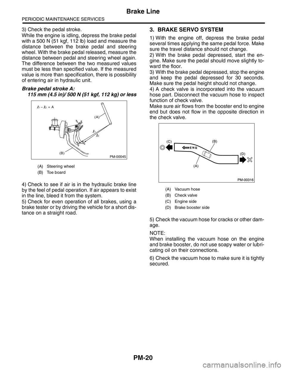
3) Check the pedal stroke.
While the engine is idling, depress the brake pedal
with a 500 N (51 kgf, 112 lb) load and measure the
distance between the brake pedal and steering
wheel. With the brake pedal released, measure the
distance between pedal and steering wheel again.
The difference between the two measured values
must be less than specified value. If the measured
value is more than specification, there is possibility
of entering air in hydraulic unit.
Brake pedal stroke A:
115 mm (4.5 in)/ 500 N (51 kgf, 112 kg) or less
4) Check to see if air is in the hydraulic brake line
by the feel of pedal operation. If air appears to exist
in the line, bleed it from the system.
5) Check for even operation of all brakes, using a
brake tester or by driving the vehicle for a short dis-
tance on a straight road.
3. BRAKE SERVO SYSTEM
1) With the engine off, depress the brake pedal
several times applying the same pedal force. Make
sure the travel distance should not change.
2) With the brake pedal depressed, start the en-
gine. Make sure the pedal should move slightly to-
ward the floor.
3) With the brake pedal depressed, stop the engine
and keep the pedal depressed for 30 seconds.
Make sure the pedal height should not change.
4) A check valve is incorporated into the vacuum
hose part. Disconnect the vacuum hose to inspect
function of check valve.
Make sure air flows from the booster end to engine
end but does not flow in the opposite direction in
the check valve.
5) Check the vacuum hose for cracks or other dam-
age.
NOTE:
When installing the vacuum hose on the engine
and brake booster, do not use soapy water or lubri-
cating oil on their connections.
6) Check the vacuum hose to make sure it is tightly
secured.
(A) Steering wheel
(B) Toe board
PM-00045(B)
(A)
= A
1
12
2
(A) Vacuum hose
(B) Check valve
(C) Engine side
(D) Brake booster side
Page 2005 of 2453

PM-22
Disc Brake Pad & Disc
PERIODIC MAINTENANCE SERVICES
15.Disc Brake Pad & Disc
A: INSPECTION
1) Jack-up the vehicle and support with rigid racks.
Then remove the wheels.
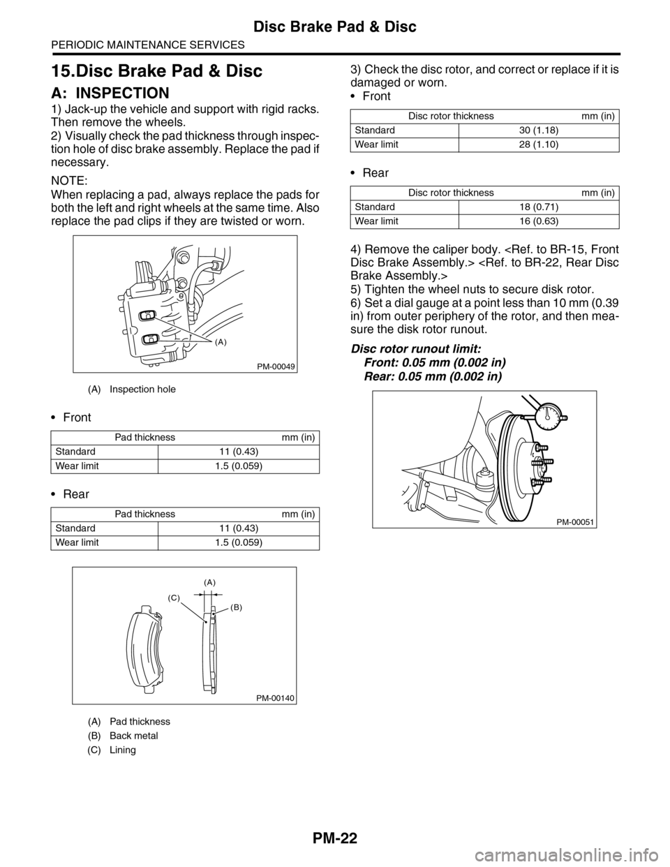
2) Visually check the pad thickness through inspec-
tion hole of disc brake assembly. Replace the pad if
necessary.
NOTE:
When replacing a pad, always replace the pads for
both the left and right wheels at the same time. Also
replace the pad clips if they are twisted or worn.
•Front
•Rear
3) Check the disc rotor, and correct or replace if it is
damaged or worn.
•Front
•Rear
4) Remove the caliper body.
Disc Brake Assembly.>
Brake Assembly.>
5) Tighten the wheel nuts to secure disk rotor.
6) Set a dial gauge at a point less than 10 mm (0.39
in) from outer periphery of the rotor, and then mea-
sure the disk rotor runout.
Disc rotor runout limit:
Front: 0.05 mm (0.002 in)
Rear: 0.05 mm (0.002 in)
(A) Inspection hole
Pad thickness mm (in)
Standard 11 (0.43)
Wear limit 1.5 (0.059)
Pad thickness mm (in)
Standard 11 (0.43)
Wear limit 1.5 (0.059)
(A) Pad thickness
(B) Back metal
(C) Lining
PM-00049
(A)
PM-00140
(A)
(C)(B)
Disc rotor thickness mm (in)
Standard 30 (1.18)
Wear limit 28 (1.10)
Disc rotor thickness mm (in)
Standard 18 (0.71)
Wear limit 16 (0.63)
PM-00051