2009 SUBARU TRIBECA ECU
[x] Cancel search: ECUPage 1611 of 2453
FU(H6DO)-50
Fuel Delivery, Return and Evaporation Lines
FUEL INJECTION (FUEL SYSTEMS)
CAUTION:
•Pull the connector to ensure it is connected
securely.
•Make sure the two retainer pawls are en-
gaged in their mating positions in the connec-
tor.
•Be sure to inspect the hoses and their con-
nections for fuel leakage.
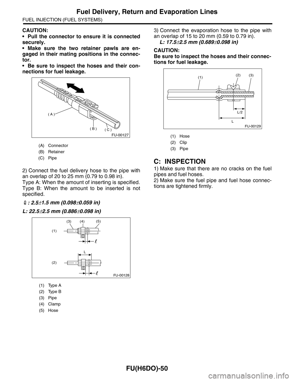
2) Connect the fuel delivery hose to the pipe with
an overlap of 20 to 25 mm (0.79 to 0.98 in).
Type A: When the amount of inserting is specified.
Type B: When the amount to be inserted is not
specified.
2: 2.5±1.5 mm (0.098±0.059 in)
L: 22.5±2.5 mm (0.886±0.098 in)
3) Connect the evaporation hose to the pipe with
an overlap of 15 to 20 mm (0.59 to 0.79 in).
L: 17.5±2.5 mm (0.689±0.098 in)
CAUTION:
Be sure to inspect the hoses and their connec-
tions for fuel leakage.
C: INSPECTION
1) Make sure that there are no cracks on the fuel
pipes and fuel hoses.
2) Make sure the fuel pipe and fuel hose connec-
tions are tightened firmly.
(A) Connector
(B) Retainer
(C) Pipe
(1) Type A
(2) Type B
(3) Pipe
(4) Clamp
(5) Hose
FU-00127
( A )
( B )( C )
(3)(4)(5)
L
(1)
(2)
FU-00128
(1) Hose
(2) Clip
(3) Pipe
FU-00129
(1)(2)
L/2
L
(3)
Page 1612 of 2453
FU(H6DO)-51
Fuel System Trouble in General
FUEL INJECTION (FUEL SYSTEMS)
29.Fuel System Trouble in General
A: INSPECTION
NOTE:
•When the vehicle is left unattended for an extended period of time, water may accumulate in the fuel tank.
Fill fuel fully to prevent those problem. And also drain water from fuel filter.
•In snow-covered areas, mountainous areas, skiing areas, etc. where ambient temperatures drop below
0°C (32°F) throughout the winter season, use a water removing agent in the fuel system to prevent freezing
fuel system and accumulating water. Fill the water removing agent at the time when the fuel reduced at half
to maintain the advantage.
•When water is accumulated in fuel filter, drain water from both the fuel filter and fuel tank or use water re-
moving agent in the fuel tank.
•Before using water removing agent, follow the cautions noted on the bottle.
Tr o u b l e a n d p o s s i b l e c a u s e C o r r e c t i v e a c t i o n
1. Insufficient fuel supply to injector
1) Fuel pump does not operate.
Defective terminal contactInspect contact, especially ground, and tighten it
securely.
Tr o u b l e i n e l e c t r o m a g n e t i c o r e l e c t r o n i c c i r c u i t p a r t s R e p l a c e t h e f a u l t y p a r t s .
2) Decline of fuel pump function Replace the fuel pump.
3) Clogged dust or water in the fuel filter Replace the fuel pump and clean or replace the fuel tank.
4) Clogged or bent fuel pipe or hose Clean, correct or replace the fuel pipe or hose.
5) Air is mixed in fuel system. Inspect or retighten each connection part.
6) Clogged or bent air breather hose or pipe Clean, correct or replace the air breather hose or pipe.
7) Damaged diaphragm of pressure regulator Replace the fuel pump.
2. Leakage or blow out of fuel
1) Loose joints of the fuel pipe Retighten.
2) Cracked fuel pipe, hose and fuel tank Replace.
3) Defective welding part on the fuel tank Replace.
4) Defective drain packing of the fuel tank Replace.
5) Clogged or bent air breather hose or air vent tubeClean, correct or replace the air breather hose or air vent
tube.
3. Gasoline smell inside of compartment
1)Loose joints at air breather hose, air vent tube and fuel filler
pipeRetighten.
2) Defective packing air tightness on the fuel saucer Correct or replace the packing.
3) Inoperative fuel pump modulator or circuit Replace.
4. Defective fuel meter indicator
1) Defective operation of fuel level sensor Replace.
2) Defective operation of fuel meter Replace.
5. Noise
1) Large operation noise or vibration of fuel pump Replace.
�
Page 1621 of 2453
GD(H6DO)-9
Diagnostic Trouble Code (DTC) Detecting Criteria
GENERAL DESCRIPTION
2. Diagnostic Trouble Code (DTC) Detecting Criteria
A: DTC P0011 INTAKE CAMSHAFT POSITION TIMING - OVER-ADVANCED
(BANK 1)
1. OUTLINE OF DIAGNOSIS
Detect the AVCS system malfunction.
There are two types of diagnosis: Crankshaft cam timing diagnosis; and slow response diagnosis. Either of
these is performed according to the status of the engine while running.
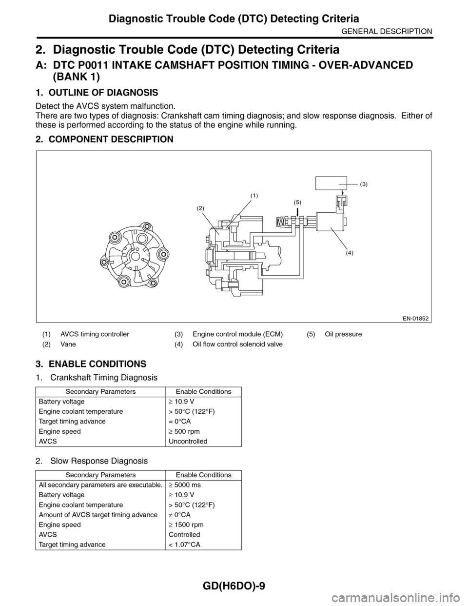
2. COMPONENT DESCRIPTION
3. ENABLE CONDITIONS
1. Crankshaft Timing Diagnosis
2. Slow Response Diagnosis
(1) AVCS timing controller (3) Engine control module (ECM) (5) Oil pressure
(2) Vane (4) Oil flow control solenoid valve
Secondary Parameters Enable Conditions
Battery voltage≥ 10.9 V
Engine coolant temperature > 50°C (122°F)
Ta r g e t t i m i n g a d v a n c e = 0 ° C A
Engine speed≥ 500 rpm
AV C S U n c o n t r o l l e d
Secondary Parameters Enable Conditions
All secondary parameters are executable.≥ 5000 ms
Battery voltage≥ 10.9 V
Engine coolant temperature > 50°C (122°F)
Amount of AVCS target timing advance≠ 0°CA
Engine speed≥ 1500 rpm
AV C S C o n t r o l l e d
Ta r g e t t i m i n g a d v a n c e < 1 . 0 7 ° C A
EN-01852
(3)
(4)
(1)(5)(2)
Page 1688 of 2453
GD(H6DO)-76
Diagnostic Trouble Code (DTC) Detecting Criteria
GENERAL DESCRIPTION
4. GENERAL DRIVING CYCLE
Perform the diagnosis only once when deceleration fuel cut occurs after rapid acceleration. (Pay attention to
the oxygen sensor voltage for the timing of the deceleration.)
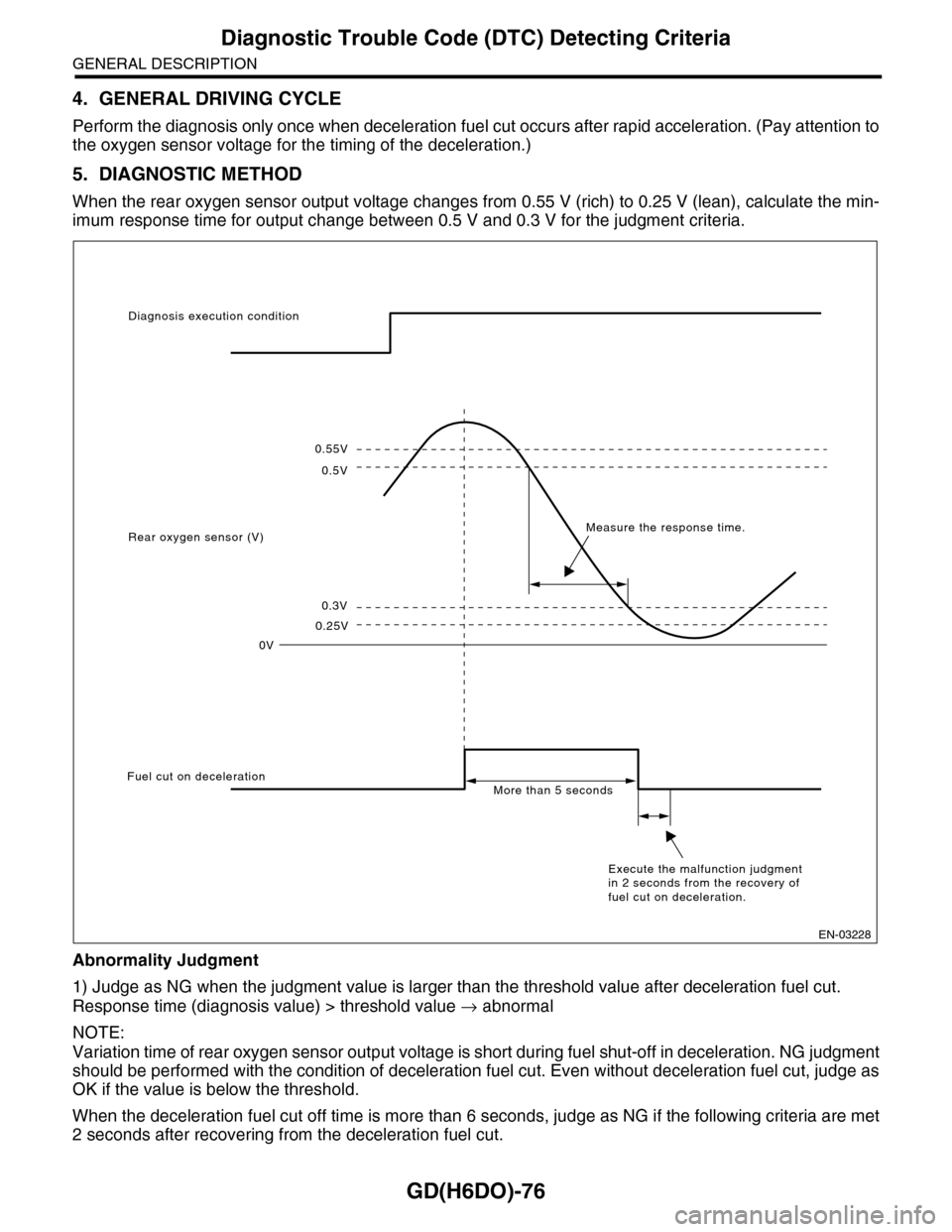
5. DIAGNOSTIC METHOD
When the rear oxygen sensor output voltage changes from 0.55 V (rich) to 0.25 V (lean), calculate the min-
imum response time for output change between 0.5 V and 0.3 V for the judgment criteria.
Abnormality Judgment
1) Judge as NG when the judgment value is larger than the threshold value after deceleration fuel cut.
Response time (diagnosis value) > threshold value → abnormal
NOTE:
Variation time of rear oxygen sensor output voltage is short during fuel shut-off in deceleration. NG judgment
should be performed with the condition of deceleration fuel cut. Even without deceleration fuel cut, judge as
OK if the value is below the threshold.
When the deceleration fuel cut off time is more than 6 seconds, judge as NG if the following criteria are met
2 seconds after recovering from the deceleration fuel cut.
0.55V
0.5V
0.3V
0.25V
0V
Diagnosis execution condition
Rear oxygen sensor (V)Measure the response time.
Fuel cut on decelerationMore than 5 seconds
Execute the malfunction judgment in 2 seconds from the recovery of fuel cut on deceleration.
EN-03228
Page 1690 of 2453
GD(H6DO)-78
Diagnostic Trouble Code (DTC) Detecting Criteria
GENERAL DESCRIPTION
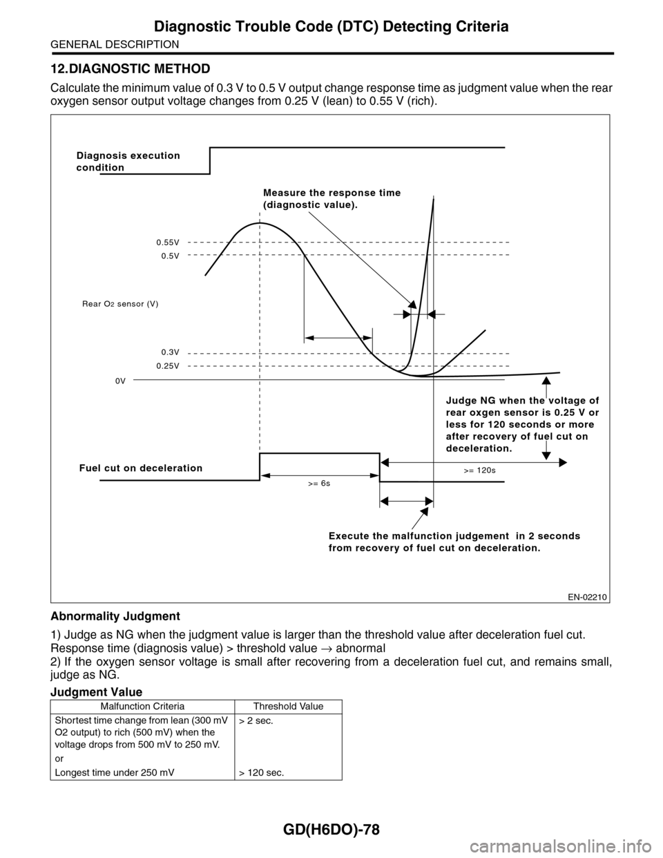
12.DIAGNOSTIC METHOD
Calculate the minimum value of 0.3 V to 0.5 V output ch a n g e r e s p on s e t im e a s ju d g m e n t v a lu e w h en th e re a r
oxygen sensor output voltage changes from 0.25 V (lean) to 0.55 V (rich).
Abnormality Judgment
1) Judge as NG when the judgment value is larger than the threshold value after deceleration fuel cut.
Response time (diagnosis value) > threshold value → abnormal
2) If the oxygen sensor voltage is small after recovering from a deceleration fuel cut, and remains small,
judge as NG.
Judgment Value
Malfunction Criteria Threshold Value
Shortest time change from lean (300 mV
O2 output) to rich (500 mV) when the
voltage drops from 500 mV to 250 mV.
> 2 sec.
or
Longest time under 250 mV > 120 sec.
EN-02210
Fuel cut on deceleration
Execute the malfunction judgement in 2 seconds
from recovery of fuel cut on deceleration.
Rear O2 sensor (V)
0V
>= 6s
>= 120s
0.25V
0.3V
0.5V
0.55V
Measure the response time
(diagnostic value).
Diagnosis execution
condition
Judge NG when the voltage of
rear oxgen sensor is 0.25 V or
less for 120 seconds or more
after recovery of fuel cut on
deceleration.
Page 1734 of 2453
GD(H6DO)-122
Diagnostic Trouble Code (DTC) Detecting Criteria
GENERAL DESCRIPTION
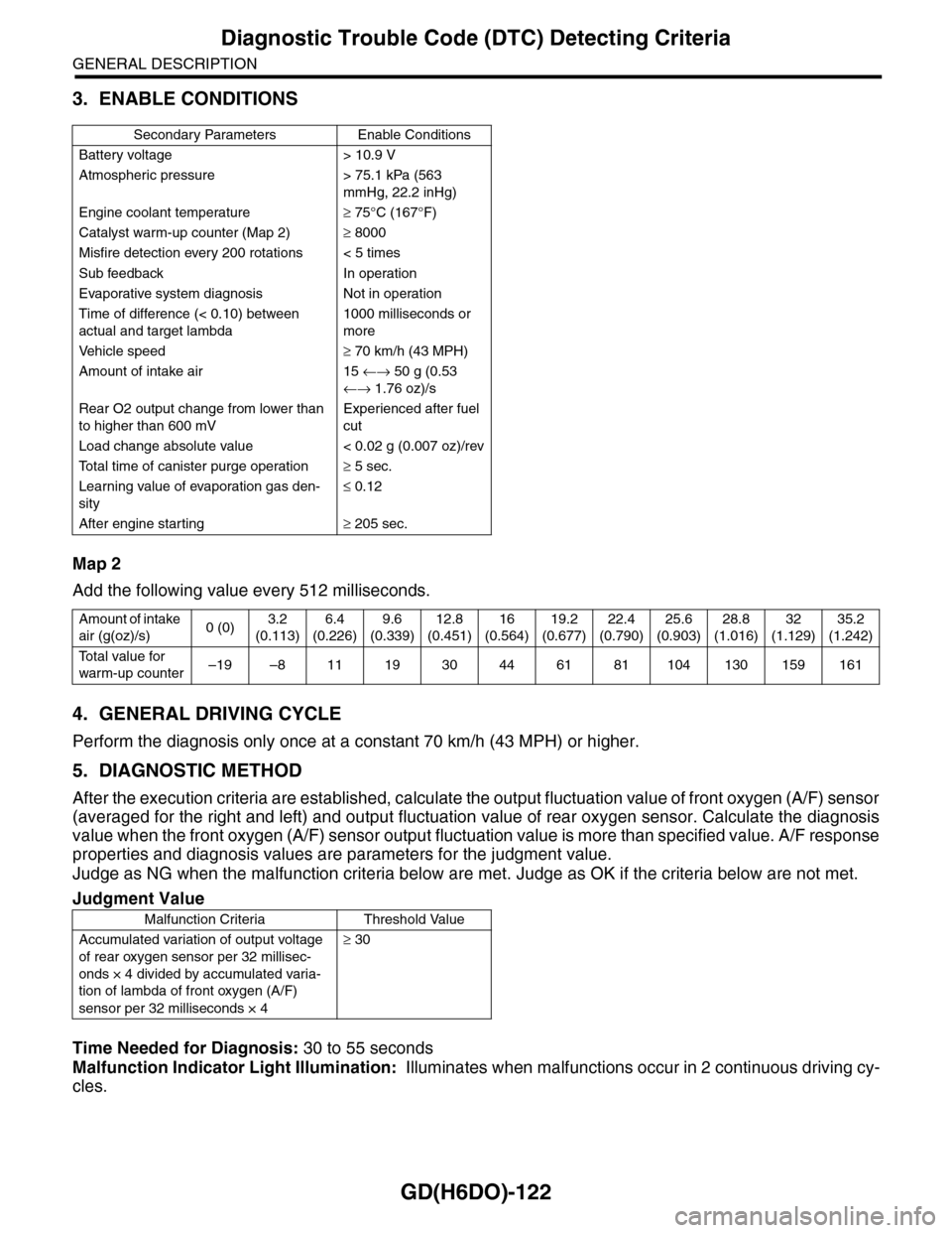
3. ENABLE CONDITIONS
Map 2
Add the following value every 512 milliseconds.
4. GENERAL DRIVING CYCLE
Perform the diagnosis only once at a constant 70 km/h (43 MPH) or higher.
5. DIAGNOSTIC METHOD
After the execution criteria are established, calculate the output fluctuation value of front oxygen (A/F) sensor
(averaged for the right and left) and output fluctuation value of rear oxygen sensor. Calculate the diagnosis
value when the front oxygen (A/F) sensor output fluctuation value is more than specified value. A/F response
properties and diagnosis values are parameters for the judgment value.
Judge as NG when the malfunction criteria below are met. Judge as OK if the criteria below are not met.
Time Needed for Diagnosis: 30 to 55 seconds
Malfunction Indicator Light Illumination: Illuminates when malfunctions occur in 2 continuous driving cy-
cles.
Secondary Parameters Enable Conditions
Battery voltage > 10.9 V
Atmospheric pressure > 75.1 kPa (563
mmHg, 22.2 inHg)
Engine coolant temperature≥ 75°C (167°F)
Catalyst warm-up counter (Map 2)≥ 8000
Misfire detection every 200 rotations < 5 times
Sub feedback In operation
Evaporative system diagnosis Not in operation
Time of difference (< 0.10) between
actual and target lambda
1000 milliseconds or
more
Ve h i c l e s p e e d≥ 70 km/h (43 MPH)
Amount of intake air 15 ←→ 50 g (0.53
←→ 1.76 oz)/s
Rear O2 output change from lower than
to higher than 600 mV
Experienced after fuel
cut
Load change absolute value < 0.02 g (0.007 oz)/rev
To t a l t i m e o f c a n i s t e r p u r g e o p e r a t i o n≥ 5 sec.
Learning value of evaporation gas den-
sity
≤ 0.12
After engine starting≥ 205 sec.
Amount of intake
air (g(oz)/s)0 (0)3.2
(0.113)
6.4
(0.226)
9.6
(0.339)
12.8
(0.451)
16
(0.564)
19.2
(0.677)
22.4
(0.790)
25.6
(0.903)
28.8
(1.016)
32
(1.129)
35.2
(1.242)
To t a l v a l u e f o r
warm-up counter–19 –8 11 19 30 44 61 81 104 130 159 161
Judgment Value
Malfunction Criteria Threshold Value
Accumulated variation of output voltage
of rear oxygen sensor per 32 millisec-
onds × 4 divided by accumulated varia-
tion of lambda of front oxygen (A/F)
sensor per 32 milliseconds × 4
≥ 30
Page 1795 of 2453
GD(H6DO)-183
Diagnostic Trouble Code (DTC) Detecting Criteria
GENERAL DESCRIPTION
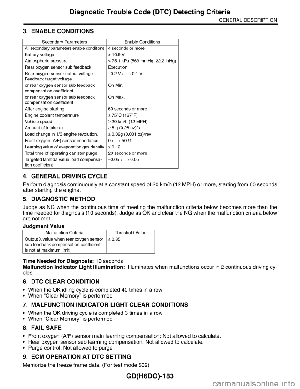
3. ENABLE CONDITIONS
4. GENERAL DRIVING CYCLE
Perform diagnosis continuously at a constant speed of 20 km/h (12 MPH) or more, starting from 60 seconds
after starting the engine.
5. DIAGNOSTIC METHOD
Judge as NG when the continuous time of meeting the malfunction criteria below becomes more than the
time needed for diagnosis (10 seconds). Judge as OK and clear the NG when the malfunction criteria below
are not met.
Time Needed for Diagnosis: 10 seconds
Malfunction Indicator Light Illumination: Illuminates when malfunctions occur in 2 continuous driving cy-
cles.
6. DTC CLEAR CONDITION
•When the OK idling cycle is completed 40 times in a row
•When “Clear Memory” is performed
7. MALFUNCTION INDICATOR LIGHT CLEAR CONDITIONS
•When the OK driving cycle is completed 3 times in a row
•When “Clear Memory” is performed
8. FAIL SAFE
•Front oxygen (A/F) sensor main learning compensation: Not allowed to calculate.
•Rear oxygen sensor sub learning compensation: Not allowed to calculate.
•Purge control: Not allowed to purge
9. ECM OPERATION AT DTC SETTING
Memorize the freeze frame data. (For test mode $02)
Secondary Parameters Enable Conditions
All secondary parameters enable conditions4 seconds or more
Battery voltage > 10.9 V
Atmospheric pressure > 75.1 kPa (563 mmHg, 22.2 inHg)
Rear oxygen sensor sub feedback Execution
Rear oxygen sensor output voltage –
Feedback target voltage
–0.2 V ←→ 0.1 V
or rear oxygen sensor sub feedback
compensation coefficient
On Min.
or rear oxygen sensor sub feedback
compensation coefficient
On Max.
After engine starting 60 seconds or more
Engine coolant temperature≥ 75°C (167°F)
Ve h i c l e s p e e d≥ 20 km/h (12 MPH)
Amount of intake air≥ 8 g (0.28 oz)/s
Load change in 1/3 engine revolution.≤ 0.02g (0.001 oz)/rev
Fr o nt ox yg e n ( A / F) s en so r im pe d an c e 0 ←→ 50 Ω
Learning value of evaporation gas density≤ 0.12
To t a l t i m e o f o p e r a t i n g c a n i s t e r p u r g e 2 0 s e c o n d s o r m o r e
Ta r g e t e d l a m b d a v a l u e l o a d c o m p e n s a -
tion coefficient
–0.05 ←→ 0.05
Judgment Value
Malfunction Criteria Threshold Value
Output λ value when rear oxygen sensor
sub feedback compensation coefficient
is not at maximum limit
≤ 0.85
Page 1797 of 2453
GD(H6DO)-185
Diagnostic Trouble Code (DTC) Detecting Criteria
GENERAL DESCRIPTION
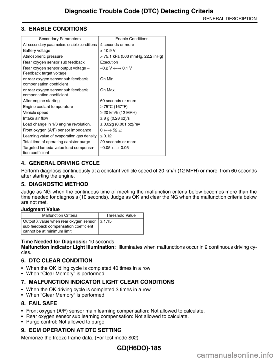
3. ENABLE CONDITIONS
4. GENERAL DRIVING CYCLE
Perform diagnosis continuously at a constant vehicle speed of 20 km/h (12 MPH) or more, from 60 seconds
after starting the engine.
5. DIAGNOSTIC METHOD
Judge as NG when the continuous time of meeting the malfunction criteria below becomes more than the
time needed for diagnosis (10 seconds). Judge as OK and clear the NG when the malfunction criteria below
are not met.
Time Needed for Diagnosis: 10 seconds
Malfunction Indicator Light Illumination: Illuminates when malfunctions occur in 2 continuous driving cy-
cles.
6. DTC CLEAR CONDITION
•When the OK idling cycle is completed 40 times in a row
•When “Clear Memory” is performed
7. MALFUNCTION INDICATOR LIGHT CLEAR CONDITIONS
•When the OK driving cycle is completed 3 times in a row
•When “Clear Memory” is performed
8. FAIL SAFE
•Front oxygen (A/F) sensor main learning compensation: Not allowed to calculate.
•Rear oxygen sensor sub learning compensation: Not allowed to calculate.
•Purge control: Not allowed to purge
9. ECM OPERATION AT DTC SETTING
Memorize the freeze frame data. (For test mode $02)
Secondary Parameters Enable Conditions
All secondary parameters enable conditions4 seconds or more
Battery voltage > 10.9 V
Atmospheric pressure > 75.1 kPa (563 mmHg, 22.2 inHg)
Rear oxygen sensor sub feedback Execution
Rear oxygen sensor output voltage –
Feedback target voltage
–0.2 V ←→ 0.1 V
or rear oxygen sensor sub feedback
compensation coefficient
On Min.
or rear oxygen sensor sub feedback
compensation coefficient
On Max.
After engine starting 60 seconds or more
Engine coolant temperature≥ 75°C (167°F)
Ve h i c l e s p e e d≥ 20 km/h (12 MPH)
Intake air flow≥ 8 g (0.28 oz)/s
Load change in 1/3 engine revolution.≤ 0.02g (0.001 oz)/rev
Fr o nt ox yg e n ( A / F) s en so r im pe d an c e 0 ←→ 52 Ω
Learning value of evaporation gas density≤ 0.12
To t a l t i m e o f o p e r a t i n g c a n i s t e r p u r g e 2 0 s e c o n d s o r m o r e
Ta r g e t e d l a m b d a v a l u e l o a d c o m p e n s a -
tion coefficient
–0.05 ←→ 0.05
Judgment Value
Malfunction Criteria Threshold Value
Output λ value when rear oxygen sensor
sub feedback compensation coefficient
cannot be at minimum limit
≥ 1.15